New Semester
Started
Get
50% OFF
Study Help!
--h --m --s
Claim Now
Question Answers
Textbooks
Find textbooks, questions and answers
Oops, something went wrong!
Change your search query and then try again
S
Books
FREE
Study Help
Expert Questions
Accounting
General Management
Mathematics
Finance
Organizational Behaviour
Law
Physics
Operating System
Management Leadership
Sociology
Programming
Marketing
Database
Computer Network
Economics
Textbooks Solutions
Accounting
Managerial Accounting
Management Leadership
Cost Accounting
Statistics
Business Law
Corporate Finance
Finance
Economics
Auditing
Tutors
Online Tutors
Find a Tutor
Hire a Tutor
Become a Tutor
AI Tutor
AI Study Planner
NEW
Sell Books
Search
Search
Sign In
Register
study help
engineering
mechanics of materials
Mechanics Of Materials 9th Edition Barry J Goodno, James M Gere - Solutions
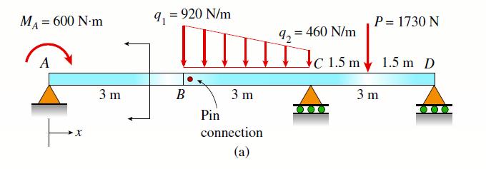
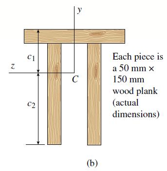
Consider the compound beam with segments AB and BCD joined by a pin connection (moment release) just right of B (see figure part a). The beam cross-section is a double-T made up of three 50 mm 3150 mm wood members (actual dimensions, see figure part b).(a) Find the centroid C of the double-T cross
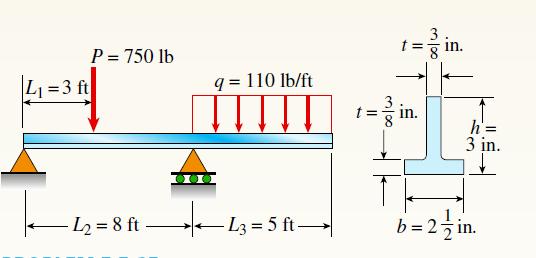
A beam with a T-section is supported and loaded as shown in the figure. The cross-section has width b = 21/2 in, height h = 3 in., and thickness t = 3/8 in.(a) Determine the maximum tensile and compressive stresses in the beam.(b) If the allowable stresses in tension and compression are 18 ksi and
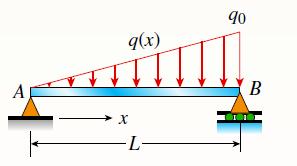
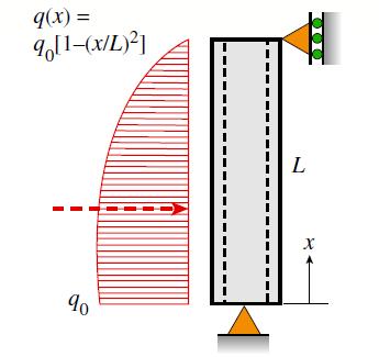
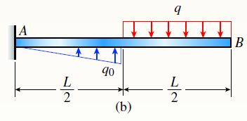
A simply supported beam is subjected to a linearly varying distributed load q(x) 0 maximum intensity q0 at B. The beam has a length L = 4 m and a rectangular cross-section with a width of 200 mm and height of 300 mm. Determine the maximum permissible value for the maximum intensity, q0, if the
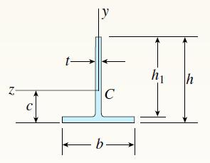
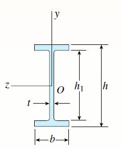
The T-beam shown in the figure has cross-sectional dimensions: b = 210 mm, t= 16 mm, h = 300 mm, and h1 = 280 mm. The beam is subjected to a shear force V = 68 kN. Determine the maximum shear stress t max in the web of the beam. C -b- hi . h
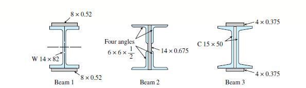
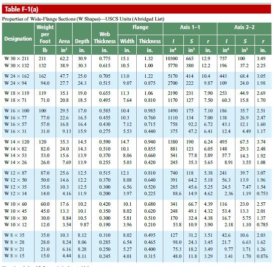
The three beams shown have approximately the same cross-sectional area. Beam 1 is a W14 x 82 with flange plates; beam 2 consists of a web plate with four angles; and beam 3 is constructed of 2 C shapes with flange plates.(a) Which design has the largest moment capacity?(b) Which has the largest
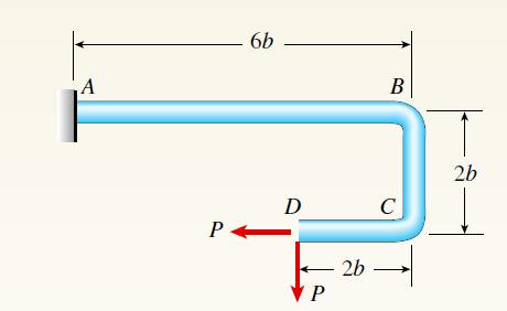
A steel bracket of the solid circular cross-section is subjected to two loads, each of which is P = 4.5 kN at D (see figure). Let the dimension variable be b = 240 mm.(a) Find the minimum permissible diameter dmin of the bracket if the allowable normal stress is 110 MPa.(b) Repeat part (a),
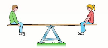
A seesaw weighing 3 lb/ft of length is occupied by two children, each weighing 90 lb (see figure). The center of gravity of each child is 8 ft from the fulcrum. The board is 19 ft long, 8 in. wide, and 1.5 in. thick. What is the maximum bending stress on the board?
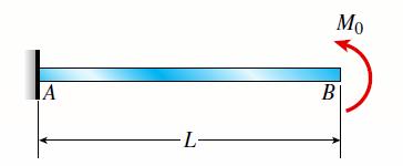
A cantilever beam is subjected to a concentrated moment at B. The length of the beam L = 3 m and the height h = 600 mm. The longitudinal strain at the top of the beam is 0.0005 and the distance from the neutral surface to the bottom surface of the beam is 300 mm. Find the radius of curvature, the
simply supported beam with a length L =10 ft and height 7 in. is bent by couples M0 into a circular arc with downward deflection d at the midpoint. If the curvature of the beam is 0.003 ft21, calculate the deflection, d, at the mid-span of the beam and the longitudinal strain at the bottom fiber
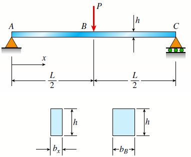
A simple beam ABC having rectangular cross sections with constant height h and varying width bx supports a concentrated load P acting at the midpoint (see figure). How should the width bx vary as a function of x in order to have a fully stressed beam? (Express bx in terms of the width bB at the
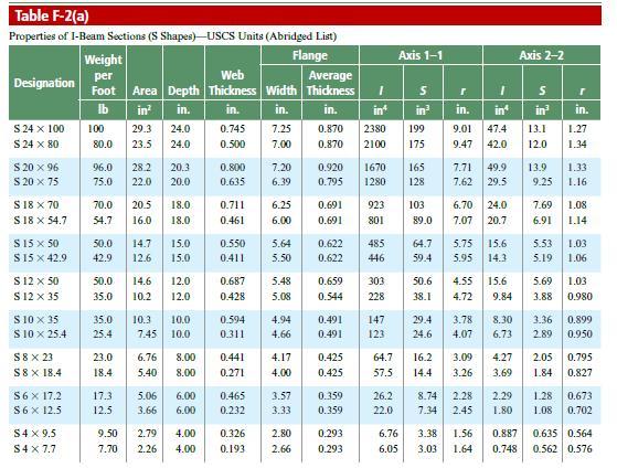
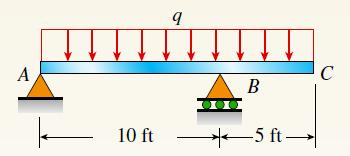
A simple beam AB is loaded as shown in the figure.(a) Calculate the required section modulus S if sallow 518,000 psi, L = 32 ft, P = 2900 lb, and q = 450 lb/ft. Then select a suitable I-beam (S shape) from Table F-2(a), Appendix F, and recalculate S taking into account the weight of the beam.
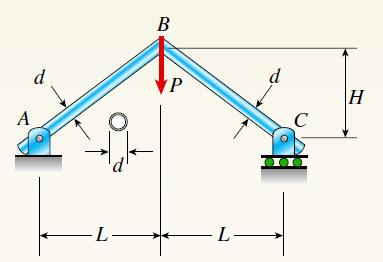
A rigid frame ABC is formed by welding two steel pipes at B (see figure). Each pipe has a cross-sectional area A =11.31 X 103 mm2, a moment of inertia I = 46.37 3106 mm4, and an outside diameter d = 200 mm. Find the maximum tensile and compressive stresses σt and σc, respectively, in the frame
A steel pipe is subjected to a quadratic distributed load over its height with the peak intensity q0 at the base (see figure). Assume the following pipe properties and dimensions: height L, outside diameter d = 200 mm, and wall thickness t =10 mm. Allowable stresses for flexure and shear are πa =
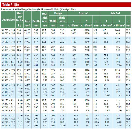
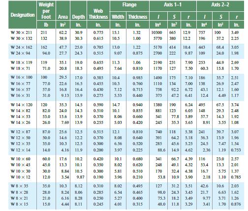
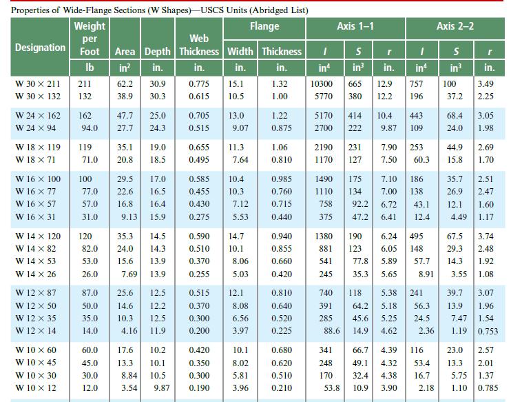
A simple beam of length L = 5 m carries a uniform load of intensity q = 5.8 kN/m and a concentrated load 22.5 kN (see figure).(a) Assuming sallow = 110 MPa, calculate the required section modulus S. Then select the most economical wide-flange beam (W shape) from Table F-1(b) in Appendix F, and
Beam ABC has simple supports at A and B and an overhang from B to C. The beam is constructed from a steel W 16 X 31. The beam must carry its own weight in addition to uniform load q = 150 lb/ft. Determine the maximum tensile and compressive stresses in the beam. A 10 ft 9 B 5 ft → C
Wide-flange shape, W18 x 71 ; V = 21 k.(see table F-1)See Table F-1 Z t- |v 0 |-b- ha h
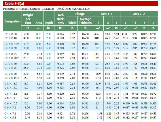
A cantilever beam AB is loaded by a uniform load q and a concentrated load P, as shown in the figure.(a) Select the most economical steel C shape from Table F-3(a) in Appendix F; use q 5 20 lb/ft and P = 300 lb (assume allowable normal stress is s a 518 ksi).(b) Select the most economical steel S
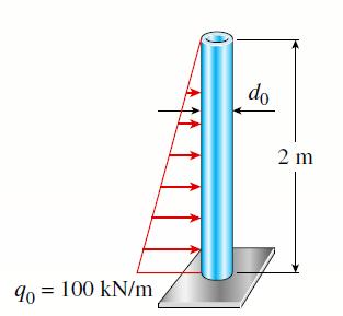
A circular pole is subjected to linearly varying distributed force with maximum intensity q0. Calculate the diameter d0 of the pole if the maximum allowable shear stress for the pole is 75 MPa. 90 = 100 kN/m do 2 m
Wide-flange shape, W 8 x 28 ; V =10 k(see Table F-1).Table F-1 N O -b- h₁ h
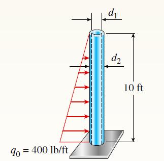
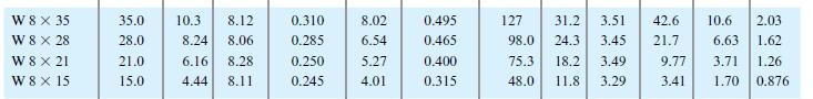
A vertical pole consisting of a circular tube of outer diameter 5 in. and inner diameter 4.5 in. is loaded by a linearly varying distributed force with a maximum intensity of q0. Find the maximum shear stress in the pole. 90 = 400 lb/ft di d2 10 ft
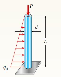
A solid circular pole is subjected to linearly varying distributed force with maximum intensity q0 at the base and an axial compressive load P at the top (see figure). Find the required diameter d of the pole if the maximum allowable normal stress is 150 MPa. Let q0 = 6.5 kN/m, P = 70 kN, and L
A simply supported beam (L = 4.5 m) must support mechanical equipment represented as a distributed load with intensity q =- 30 kN/m acting over the middle segment of the beam (see figure). Select the most economical W-shape steel beam from Table F-1(b) to support the loads. Consider both the
A pole is fixed at the base and is subjected to a linearly varying distributed force with the maximum intensity of q0 and an axial compressive load P = 20 kips at the top (see figure). The pole has a circular cross-section with an outer diameter of 5 in. and an inner diameter of 4.5 in. Find the
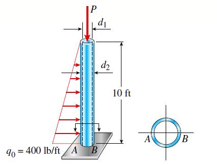
A cable with force P is attached to a frame at A and runs over a frictionless pulley at D. Find expressions for shear force V and moment M at x = L/2 of beam BC. L/2 A B L/2 Cable V, M at L/2 L/2 D L/2 C P
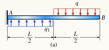
Cantilever beam AB carries an upward uniform load of intensity q1 from x = 0 to L/2 (see Figure) and a downward uniform load of intensity q from x = L/2 to L. (a) Find q1 in terms of q if the resulting moment at A is zero. Draw V and M diagrams for the case of both q and q1 as applied
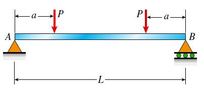
Draw the shear-force and bending-moment diagrams for a simple beam AB supporting two equal concentrated loads P (see figure). Repeat if the left-hand load is upward and the right-hand load is downward. A -L- PL- -a- B 000
Two pipes (L1 = 2.5 m and L2 =1.5 m) are joined at B by flange plates (thickness tf =14 mm) with five bolts (dbf =13 mm) arranged in a circular pattern (see figure). Also, each pipe segment is attached to a wall (at A and C, see figure) using a base plate (tb = 15 mm) and four bolts (dbb =16 mm).
A steel tube (G =11.5 X 10⁶ psi) has an outer diameter d2 = 2.0 in. and an inner diameter d1 = 1.5 in. When twisted by a torque T, the tube develops a maximum normal strain of 170 X 10-6. What is the magnitude of the applied torque T?
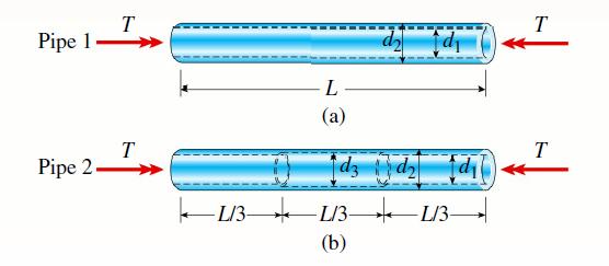
Two circular aluminum pipes of equal length L = 24 in. are loaded by torsional moments T. Pipe 1 has outside and inside diameters, d2 = 3 in. and d1 = 2.5 in, respectively. Pipe 2 has a constant outer diameter of d2 along its entire length and an inner diameter of d1 but has an increased inner
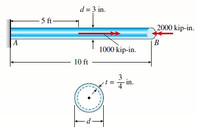
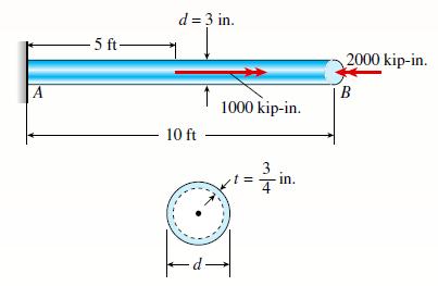
A circular tube AB is fixed at one end and free at the other. The tube is subjected to concentrated torques as shown in the figure. If the outer radius of the tube is 1.5 in. and the thickness is 3/4 in., calculate the strain energy stored in the tube. Let G = 11,800 ksi. A -5 ft- d = 3 in. 10
Solve the preceding problem for the following data: b = 8.0 in., k =16 lb/in., a = 45, and P =10 lb.(a)(b) A 0000 T B k T I | C
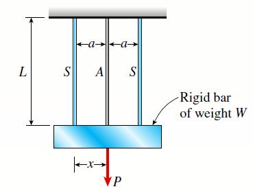
A rigid bar of weight W = 800 N hangs from three equally spaced vertical wires (length L = 150 mm, spacing a = 50 mm): two of steel and one of aluminum. The wires also support a load P acting on the bar. The diameter of the steel wires is ds = 2 mm, and the diameter of the aluminum wire is da = 4
Solve Prob. 2.8-1 if the collar has weight W = 50 lb, the height h = 2.0 in., the length L = 3.0 ft, the cross-sectional area A = 0.25 in2, and the modulus of elasticity E = 30,000 ksi. A k -10 ft- 90 = 2 kips/ft B
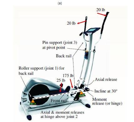
An elliptical exerciser machine (see figure part a) is composed of front and back rails. A simplified plane-frame model of the back rail is shown in figure part b. Analyze the plane-frame model to find reaction forces at supports A, B, and C for the position and applied loads given in figure part
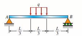
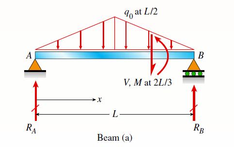
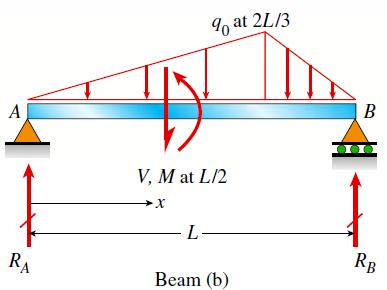
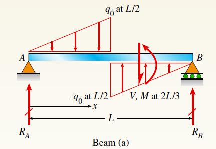
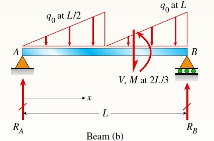
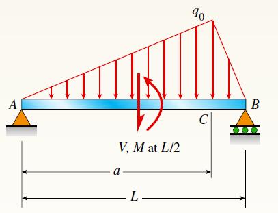
Find expressions for shear force V and moment M at x = 2L/3 of the beam (a) in terms of peak load intensity q0 and beam length variable L. Repeat for beam (b) but at x = L/2. A RA -X L % at L/2 V, M at 2L/3 Beam (a) B RB
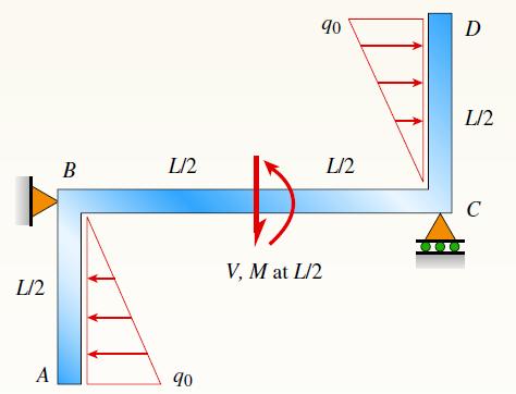
Find expressions for shear force V and moment M at x = L/2 of beam BC. Express V and M in terms of peak load intensity q0 and beam length variable L. L/2 A B L/2 90 V, M at L/2 90 L/2 D L/2 C
Find expressions for shear force V and moment M at x = 2L/3 of beam (a) in terms of peak load intensity q0 and beam length variable L. Repeat for beam (b). A RA 9 at L/2 at L/2 ·X -L- Beam (a) V, M at 2L/3 B RB
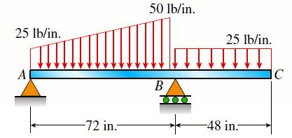
Beam ABC has simple supports at A and B, an overhang BC and the distributed loading shown in the figure. Draw the shear-force and bending-moment diagrams for this beam. 25 lb/in. A -72 in.- 50 lb/in. B 000 25 lb/in. -48 in C
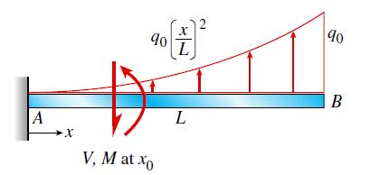
Find expressions for shear force V and moment M at x =x0 of beam AB in terms of peak load intensity q0 and beam length variable L. Let x0 = 2L/3. A X 90+² L 17 V, M at xo L 90 B
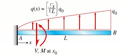
Find expressions for shear force V and moment M at x = x0 of beam AB in terms of peak load intensity q0 and beam length variable L. Let x0 = L/2. A q(x) = ·X X I% V, M at xo L 90 B
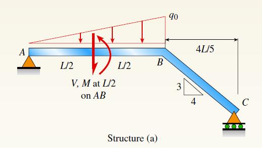
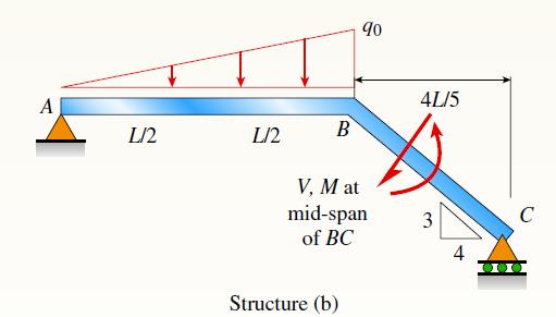
Find expressions for shear force V and moment M at x = L/2 of beam AB in structure (a). Express V and M in terms of peak load intensity q0 and beam length variable L. Repeat for structure (b) but find V and M at mid-span of member BC. A L/2 V, M at L/2 on AB L/2 B Structure (a) 90 3 4L/5 4 C
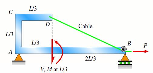
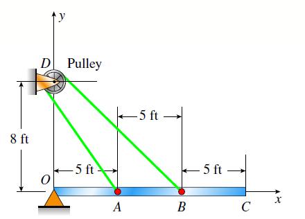
A cable with force P is attached to a frame at D and runs over a frictionless pulley at B. Find expressions for shear force V and moment M at x = L/3 of beam AB. C L/3 A L/3 L/3 D V, M at L/3 Cable 21/3 B P
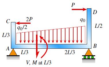
Frame ABCD carries two concentrated loads (2P at C and P at D, see figure) and also a linearly varying distributed load on AB. Find expressions for shear force V and moment M at x = L/3 of beam AB in terms of peak load intensity q0, force P, and beam length variable L. Let q0 = P/L.
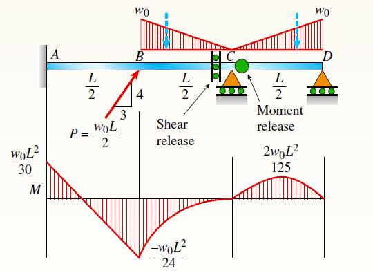
First, solve for reactions using statics; then plot axial force (N) and shear force (V) diagrams. Confirm that the moment diagram is that shown below. Label all critical N, V, and M values and also the distance to points where N, V, and/or M are zero. First, solve for reactions using statics; then
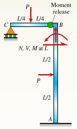
Frame ABC has a moment release just left of joint B. Find axial force N, shear force V, and moment M at the top of column AB. Write variables N, V, and M in terms of variables P and L. P L/4 200 L/4 N, V, M at L P Moment release L/2 L/2 A B
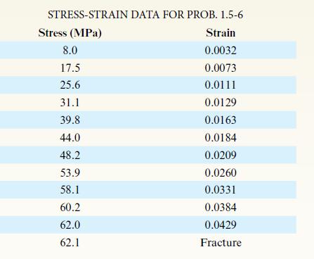
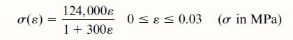
A specimen of a methacrylate plastic is tested in tension at room temperature (see figure), producing the stress-strain data listed in the accompanying table. Plot the stress-strain curve and determine the proportional limit, modulus of elasticity (which is the slope of the initial part of the
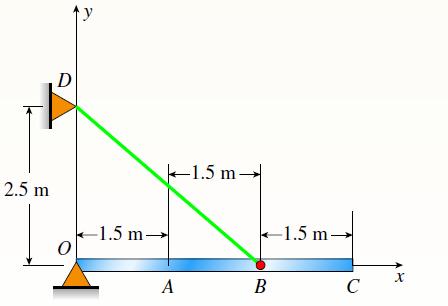
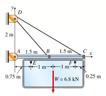
Cable DB supports canopy beam OABC as shown in the figure. Find the required cross-sectional area of cable BD if the allowable normal stress is 125 MPa. Determine the required diameter of the pins at O, B, and D if the allowable stress in shear is 80 MPa. Assume that canopy beam weight is W = 8kN.
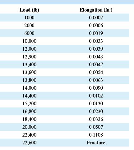
The data shown in the accompanying table are from a tensile test of high-strength steel. The test specimen has a diameter of 0.505 in. and a gage length of 2.00 in. At fracture, the elongation between the gage marks is 0.12 in. and the minimum diameter is 0.42 in. Plot the conventional
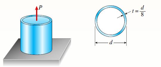
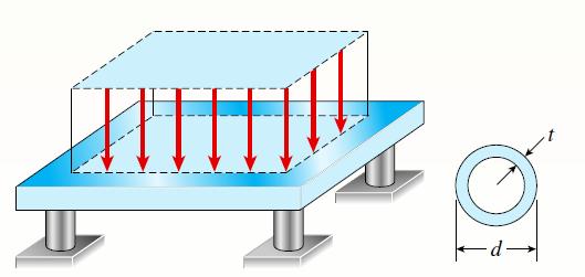
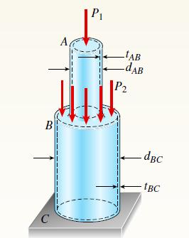
A copper alloy pipe with a yield stress σ = 290 MPa is to carry an axial tensile load P =1500 kN. Use a factor of safety of 1.8 against yielding.(a) If the thickness t of the pipe is one-eighth of its outer diameter, what is the minimum required outer diameter dmin?(b) Repeat part (a) if the tube
A steel pad supporting heavy machinery rests on four short, hollow, cast iron piers. The ultimate strength of the cast iron in compression is 50 ksi. The outer diameter of the piers is d = 4.5 in., and the wall thickness is t = 0.40 in. Using a factor of safety of 3.5 with respect to the ultimate
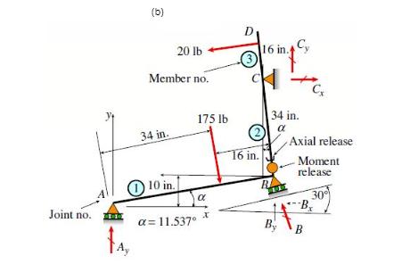
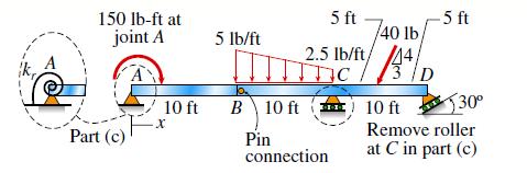
Segments AB and BCD of beam ABCD are pin connected at x =10 ft. The beam is supported by pin support at A and roller supports at C and D; the roller at D is rotated by 308 from the x axis (see figure). A trapezoidal distributed load on BC varies in intensity from 5 = lb/ft at B to 2.5 lb/ft at C. A
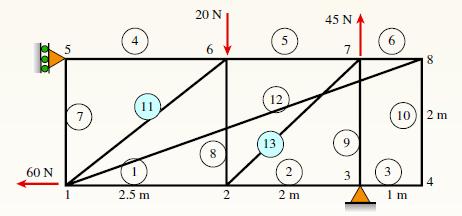
Consider the plane truss with a pin support at joint 3 and a vertical roller support at joint 5 (see figure).(a) Find reactions at support joints 3 and 5.(b) Find axial forces in truss members 11 and 13. 000 60 N 5 7 4 11 2.5 m 20 N 8 2 5 12 13 2 2m 45 NA 7 9 3 8 10) 2 m 3 Im 4
A continuous cable (diameter 6 mm) with tension force T is attached to a horizontal frame member at B and C to support a sign structure. The cable passes over a small frictionless pulley at D. The wire is made of a copper alloy, and the stress stress-strain relationship for the wire is(a) Find the
Continuous cable ADB runs over a small frictionless pulley at D to support beam OABC that is part of an entrance canopy for a building (see figure). Assume that the canopy segment has a weight of W = 1700 lb.(a) Find the required cross-sectional area of cable ADB if the allowable stress is 18
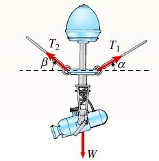
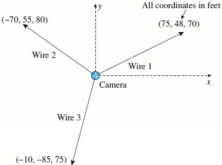
Two steel wires support a moveable overhead camera weighing W = 2° lb (see fgure part a) used for close-up viewing of field action at sporting events. At some instant, wire 1 is at an angle a = 228 to the horizontal and wire 2 is at angle b = 40. Wires 1 and 2 have diameters of 30 and 35 mils,
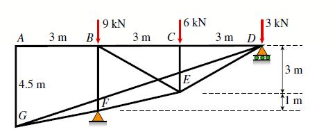
A plane truss has a pin support at A and a roller support at E (see figure).(a) Find reactions at all supports.(b) Find the axial force in truss member FE. A 4.5 m G 3 m B 9 kN 3 m C 6 kN E 3m D 13 kN 000 3 m
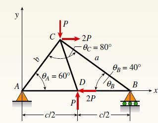
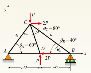
Find support reactions at A and B and then use the method of joints to find all member forces. Let c = 8 ft and P = 20 kips.(a) Find reactions at both supports.(b) Find the axial force in truss member FE. A с A = 60° -c/2- 2P Øc = 80° a D 2P c/2 0B = 400 B OB X
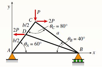
Find support reactions at A and B and then use the method of joints to find all member forces. Let b = 3 m and P = 80 kN. A b/2 2P D b/2 A = 60° 2P 8c = 80° a B = 40° B →X
Repeat 1.3-9 but use the method of sections to find member forces in AC and BD.Repeat 1.3-9Find support reactions at A and B and then use the method of joints to find all member forces. Let c = 8 ft and P = 20 kips. y A A = 60° - c/2- P 2P 8c=80° a D 2P B = 40° B OB c/2- X
Find support reactions at A and B and then use the method of joints to find all member forces. Let c = 8 ft and P = 20 kips. y A A = 60° - c/2- P 2P 8c=80° a D 2P B = 40° B OB c/2- X
Repeat 1.3-10 but use the method of sections to find member forces in AB and DC.(a) Find reaction force components Bx, Bz, and Oz.(b) Find the axial force in truss member AC.Problem 1.3-10Find support reactions at A and B and then use the method of joints to find all member forces. Let b = 3 m and
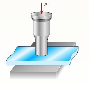
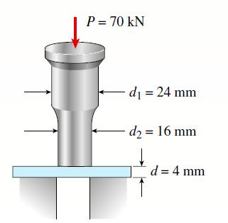
A steel punch consists of two shafts: upper shaft and lower shaft. Assume that the upper shaft has a diameter d1 = 24 mm and the bottom shaft has a diameter d2 =16 mm. The punch is used to insert a hole in a 4 mm plate, as shown in the figure. If a force P = 70 kN is required to create the hole,
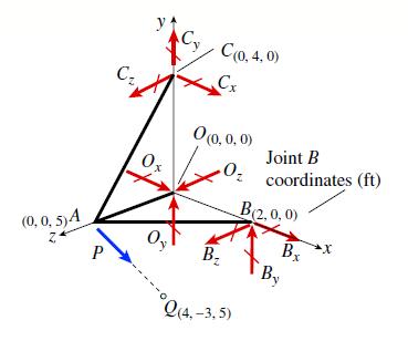
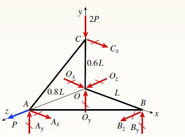
A space truss has three-dimensional pin supports at joints O, B, and C. Load P is applied at joint A and acts toward point Q. Coordinates of all joints are given in feet (see figure).(a) Find reaction force components Bx, Bz, and Oz.(b) Find the axial force in truss member AC.
A space truss is restrained at joints O, A, B and C, as shown in the figure. Load P is applied at joint A and load 2P acts downward at joint C.(a) Find reaction force components Ax, By, and Bz in terms of load variable P.(b) Find the axial force in truss member AB in terms of load variable P.
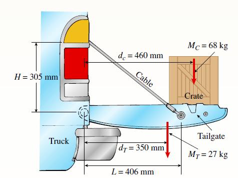
Solve the preceding problem if the mass of the tailgate is MT = 27 kg and that of the crate is MC = 68 kg. Use dimensions H = 305 m m, L = 406 mm, dC = 460 mm, and dT = 350 mm. The cable cross-sectional area is Ae = 11.0 mm2.(a) Find the tensile force T and normal stress s in each cable.(b) If
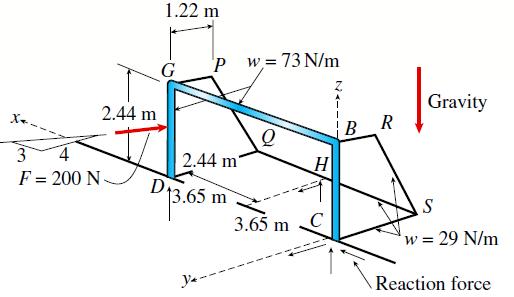
A soccer goal is subjected to gravity loads (in the 2z direction, w = 73 N/m for DG, BG, and BC; w = 29 N/m for all other members; see figure) and a force F = 200 N applied eccentrically at the mid-height of member DG. Find reactions at supports C, D, and H. 1.22 m 2.44 m I 3 4 F= 200 N- Pw=73
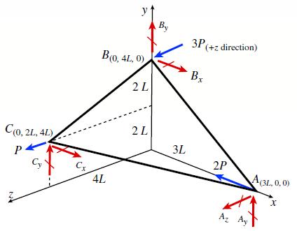
A space truss is restrained at joints A, B and C, as shown in the figure. Load 2P is applied at in the 2x direction at joint A, load 3P acts in the 1z direction at joint B, and load P is applied in the 1z direction at joint C. Coordinates of all joints are given in terms of dimension variable L.(a)
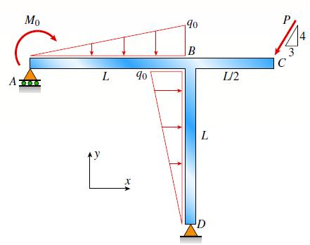
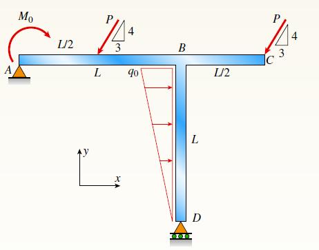
Find support reactions at A and D and then calculate the axial force N, shear force V, and bending moment M at mid-span of AB. Let L = 14 ft, q0 =12 lb/ft, P = 50 lb, and M0 = 300 lb-ft. A Mo y L X 90 90 B L D 1/2 J C 3
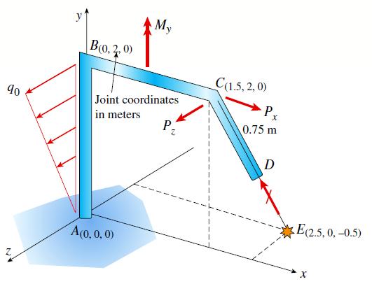
Space frame ABCD is clamped at 3A, except it is free to translate in the x direction. There is also roller support at D, which is normal to line CDE. A triangularly distributed force with peak intensity q0 = 75 N/m acts along AB in the positive z direction. Forces Px = 60 N and Pz = − 45 N
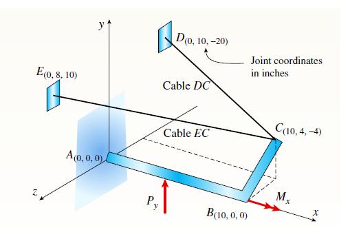
Space frame ABC is clamped at A, except it is free to rotate at A about the x and y axes. Cables DC and EC support the frame at C. Force Py = − 50 lb is applied at the mid-span of AB, and a concentrated moment Mx = − 20 in.− lb acts at joint B.(a) Find reactions at support A.(b) Find cable
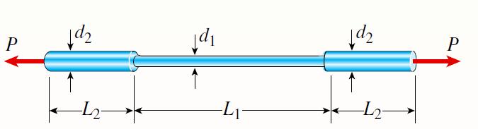
A round brass bar of a diameter d1 = 20 mm has upset ends each with a diameter d2 = 26 mm (see figure). The lengths of the segments of the bar are L1 = 0.3 m and L2 = 0.1 m. Quarter-circular fillets are used at the shoulders of the bar, and the modulus of elasticity of the brass is E = 100 GPa. If
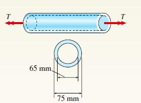
A circular steel tube with an outer diameter of 75mm and inner diameter of 65mm is subjected to torques T at its ends. Calculate the maximum permissible torque Tmax if the allowable normal strain is εa = 5 X 10⁻⁴. Assume that G = 75GPa. T 65 mm. 75 mm T
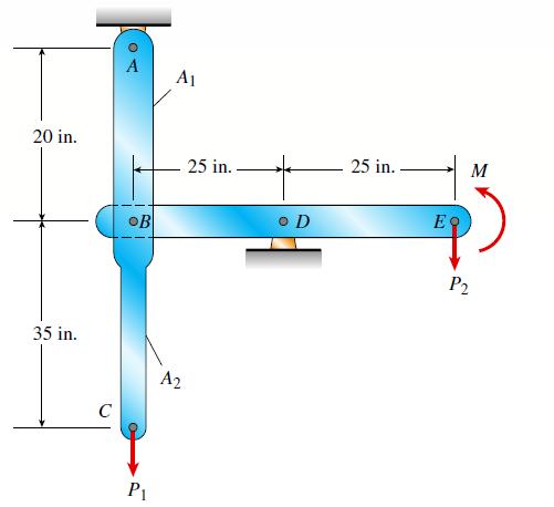
A vertical steel bar ABC is pin-supported at its upper end and loaded by a force P1 at its lower end. A horizontal beam BDE is pinned to the vertical bar at joint B and supported at point D. Load P2 and moment M are applied at end E. Calculate the vertical displacement dC at point C if the
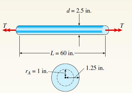
A solid steel bar of circular cross-section has diameter d = 2.5 in., L = 60 in., and shear modulus of elasticity G =11.5 X10⁶ psi. The bar is subjected to torques T = 300 lb-ft at the ends. Calculate the angle of twist between the ends. What is the maximum shear stress and the shear stress at a
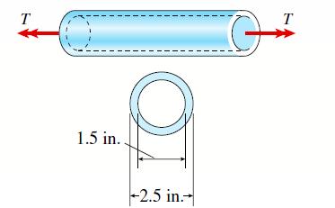
Repeat Problem 3.3-1, but now use a circular tube with outer diameter do = 2.5 in. and inner diameter di = 1.5 in.Problem 3.3-1A solid steel bar of circular cross-section has diameter d = 2.5 in., L = 60 in., and shear modulus of elasticity G =11.5 X10⁶ psi. The bar is subjected to torques T = 300
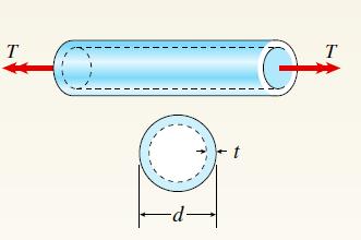
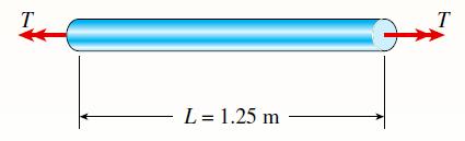
A copper tube with a circular cross-section has a length L =1.25 m, thickness t = 2 mm, and shear modulus of elasticity G = 45 GPa. The bar is de signed to carry a 300 N ? m torque acting at the ends. If the allowable shear stress is 25 MPa and the allowable angle of twist between the ends is 2.58,
A solid copper bar of circular cross-section has a length L = 1.25 m and shear modulus of elasticity G = 45 GPa. The bar is designed to carry a 250 N · m torque acting at the ends. If the allowable shear stress is 30 MPa and the allowable angle of twist between the ends is 2.5°, what is the
A circular tube AB is fixed at one end and free at the other. The tube is subjected to concentrated torques as shown in the figure. If the outer radius of the tube is 1.5 in. and the thickness is 3/4 in., calculate the strain energy stored in the tube. Let G = 11,800 ksi. A -5 ft- d = 3 in. 10
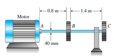
A solid steel shaft ABC with diameter d = 40 mm is driven at A by a motor that transmits 75 kW to the shaft at 15 Hz. The gears at B and C drive machinery requiring power equal to 50 kW and 25 kW, respectively. Compute the maximum shear stress and angle of twist in the shaft between the motor at A
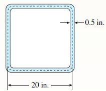
A square tube section has side dimension of 20 in. and a thickness of 0.5 in. If the section is used for a 10-ft-long beam subjected to 1250 kip-in. torque at both ends, calculate the maximum shear stress and the angle of twist between the ends. Use G = 11,600 ksi. -20 in. - -0.5 in.
An aluminum tube has an inside diameter d1 = 50 mm, shear modulus of elasticity G = 27 GPa, n = 0.33, and torque T = 4.0 kN ? m. The allowable shear stress in the aluminum is 50 MPa, and the allowable normal strain is 900 X 10-6.(a) Determine the required outside diameter d2.(b) Re-compute the
Find expressions for shear force V and moment M at mid-span of beam AB in terms of peak load intensity q0 and beam length variables a and L Let a = 5L/6. A V, M at L/2 a L- 90 C B DO
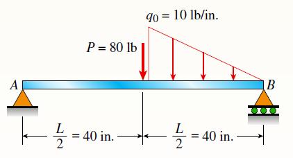
The simple beam AB supports a triangular load of maximum intensity q0 =10 lb/in. acting over one-half of the span and a concentrated load P = 80 lb acting at midspan (see figure). Draw the shear-force and bending-moment diagrams for this beam. Al 늘= P = 80 lb = 40 in. 90 = 10 lb/in. -- = 40 in. B
Two tubes (AB, BC) of the same material are connected by three pins (pin diameter 5d p) just left of B as shown in the figure. The properties and dimensions for each tube are given in the figure. Torque 2T is applied at x = 2L/5 and uniformly distributed torque intensity t0 = 3T /L is applied on
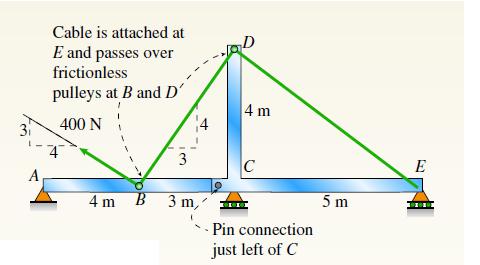
A plane frame is restrained at joints A and D, as shown in the figure. Members AB and BCD are pin connected at B. A triangularly distributed lateral load with peak intensity of 80 N/m acts on CD. An inclined concentrated force of 200 N acts at the midspan of BC.(a) Find reactions at supports A and
Find support reactions at A and D and then calculate the axial force N, shear force V, and bending moment M at the mid-span of column BD. Let L = 4 m, q0 =160 N/m, P = 200 N, and M0 = 380 N · m. A Mo L/2 744 3 L X 90 B L D 000 L/2 3 4
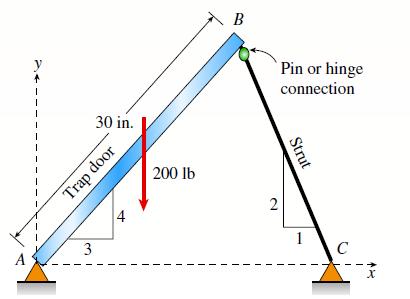
A 200-lb trap door (AB) is supported by a strut (BC) which is pin connected to the door at B(see figure).(a) Find reactions at supports A and C.(b) Find internal stress resultants N, V, and M on the trap door at 20 in. from A. A 3 30 in. Trap door t 200 lb B 2 Pin or hinge connection Strut 1 C X
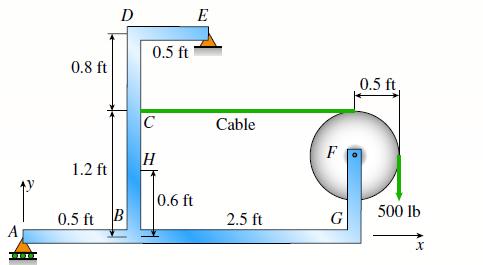
A plane frame is constructed by using a pin connection between segments ABC and CDE. The frame has pin supports at A and E and joint loads at B and D (see figure).(a) Find reactions at supports A and E.(b) Find the resultant force in the pin at C. A 0.8 ft 1.2 ft D 0.5 ft B 0.5 ft C H 0.6
A plane frame with pin supports at A and E has a cable attached at C, which runs over a frictionless pulley at F (see figure). The cable force is known to be 500 lb.(a) Find reactions at supports A and E.(b) Find internal stress resultants N, V, and M at point H. A 0.8 ft 1.2 ft D 0.5 ft B 0.5
A plane frame with a pin support at A and roller supports at C and E has a cable attached at E, which runs over frictionless pulleys at D and B (see figure). The cable force is known to be 400 N. There is a pin connection just to the left of joint C.(a) Find reactions at supports A, C, and E.(b)
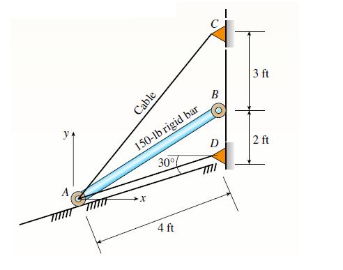
A 150-lb rigid bar AB, with frictionless rollers at each end, is held in the position shown in the figure by a continuous cable CAD. The cable is pinned at C and D and runs over a pulley at A.(a) Find reactions at supports A and B.(b) Find the force in the cable. ya A Cable 150-lb rigid
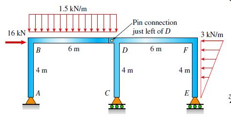
A plane frame has a pin support at A and roller supports at C and E (see figure). Frame segments ABD and CDEF are joined just left of joint D by a pin connection.(a) Find reactions at supports A, C, and E.(b) Find the resultant force in the pin just left of D. 16 kN B 4 m 1.5 kN/m 6m C D Pin
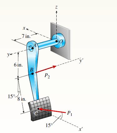
A plane frame has a pin support at A and roller supports at C and E (see figure). Frame segments ABD and CDEF are joined just left of joint D by a pin connection.(a) Find reactions at supports A, C, and E.(b) Find the resultant force in the pin just left of D. y* X 7 in.7 6 in. 15° 8
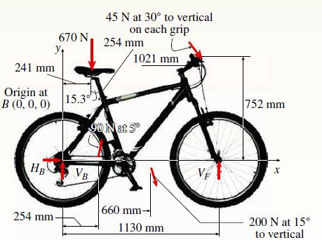
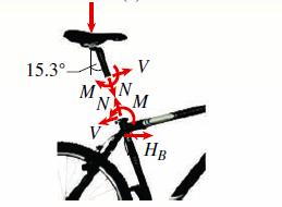
A mountain bike is moving along a flat path at constant velocity. At some instant, the rider (weight = 670 N) applies pedal and hand forces, as shown in figure part a.(a) Find reaction forces at the front and rear hubs. (Assume that the bike is pin supported at the rear hub and roller supported at
The rails of a railroad track are welded together at their ends (to form continuous rails and thus eliminate the clacking sound of the wheels) when the temperature is 60°F. What compressive stress s is produced in the rails when they are heated by the sun to 120°F if the coefficient of thermal
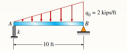
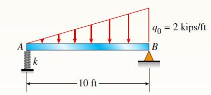
A 10-ft rigid bar AB is supported with a vertical translational spring at A and a pin at B. The bar is subjected to a linearly varying distributed load with maximum intensity q0. Calculate the vertical deformation of the spring if the spring constant is 4 kips/in. A k -10 ft- 90 = 2 kips/ft B
A long, rectangular copper bar under a tensile load P hangs from a pin that is supported by two steel posts (see figure). The copper bar has a length of 2.0 m, a cross-sectional area of 4800 mm2, and a modulus of elasticity Ec =120 GPa. Each steel post has a height of 0.5 m, a cross-sectional area
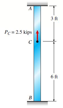
A steel bar with a uniform cross-section is fixed at both ends. A load P = 2.5 kips is applied at point C. The bar has a cross-sectional area of 8 in2. Calculate the reactions at joints A and B and the displacement at joint C. Assume that the modulus of elasticity E = 29,000 ksi. A Pc = 2.5
A round brass bar of a diameter d1 = 20 mm has upset ends each with a diameter d2 = 26 mm (see figure). The lengths of the segments of the bar are L1 = 0.3 m and L2 = 0.1 m. Quarter-circular fillets are used at the shoulders of the bar, and the modulus of elasticity of the brass is E =100 GPa. If
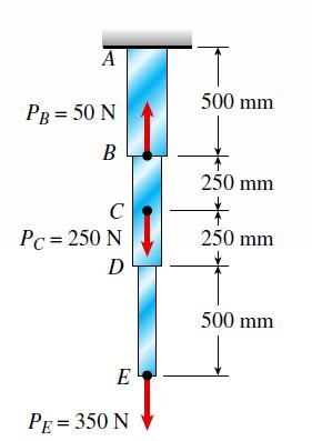
A vertical bar consists of three prismatic segments A1, A2, and A3 with cross-sectional areas of 6000 mm2, 5000 mm2, and 4000 mm2, respectively. The bar is made of steel with E = 200 GPa. Calculate the displacements at points B, D, and E. Ignore the weight of the bar. A PB = 50 N B C Pc = 250
Showing 1400 - 1500
of 1529
First
2
3
4
5
6
7
8
9
10
11
12
13
14
15
16
Step by Step Answers