New Semester
Started
Get
50% OFF
Study Help!
--h --m --s
Claim Now
Question Answers
Textbooks
Find textbooks, questions and answers
Oops, something went wrong!
Change your search query and then try again
S
Books
FREE
Study Help
Expert Questions
Accounting
General Management
Mathematics
Finance
Organizational Behaviour
Law
Physics
Operating System
Management Leadership
Sociology
Programming
Marketing
Database
Computer Network
Economics
Textbooks Solutions
Accounting
Managerial Accounting
Management Leadership
Cost Accounting
Statistics
Business Law
Corporate Finance
Finance
Economics
Auditing
Tutors
Online Tutors
Find a Tutor
Hire a Tutor
Become a Tutor
AI Tutor
AI Study Planner
NEW
Sell Books
Search
Search
Sign In
Register
study help
engineering
mechanics of materials
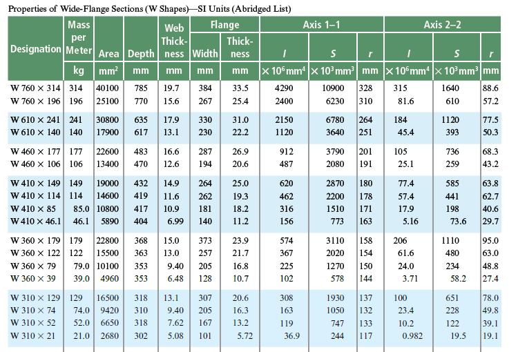
Mechanics Of Materials 9th Edition Barry J Goodno, James M Gere - Solutions
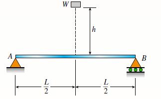
An object of weight W is dropped onto the midpoint of a simple beam AB from a height h (see figure). The beam has a rectangular cross-section of area A. Assuming that h is very large compared to the deflection of the beam when the weight W is applied statically, obtain a formula for the maximum
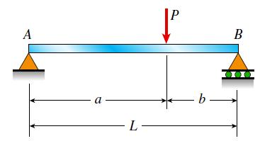
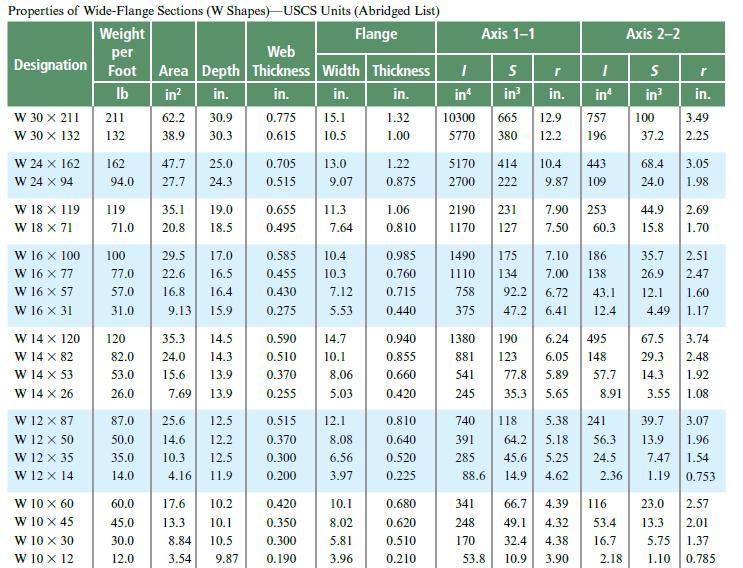
A simply supported beam is loaded with a point load, as shown in the figure. The beam is a steel wide flange (W 12 X 35) in strong axis bending. Calculate the maximum deflection of the beam and the rotation at joint A if L = 10 ft, a = 7 ft, b = 3 ft, and P =10 kips. Neglect the weight of the
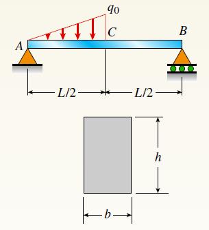
A simply supported beam (E = 1600 ksi) is loaded by a triangular distributed load from A to C (see figure). The load has a peak intensity q0 = 10 lb/ ft, and the deflection is known to be 0.01 in. at point C. The length of the beam is 12 ft, and the ratio of the height to the width of the
A heavy object of weight W is dropped onto the midpoint of a simple beam AB from a height h. Obtain a formula for the maximum bending stress smax due to the falling weight in terms of h, σst, and πst, where σst is the maximum bending stress and πst is the deflection at the midpoint when the
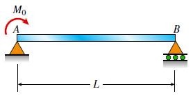
A simple beam AB of length L is loaded at the left-hand end by a couple of moments M0. Determine the angle of rotation uA at support A. Mo L B 30
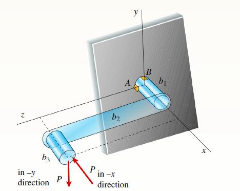
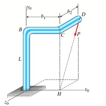
A crank arm consists of a solid segment of length b1 and diameter d, a segment of length b2, and a segment of length b3, as shown in the figure. Two loads P act as shown: one parallel to -x and another parallel to -y. Each load P equals 1.2 kN. The crankshaft dimensions are b1 = 75 mm, b2 = 125 mm,
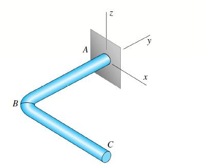
An arm ABC lying in a horizontal plane and supported at A (see figure) is made of two identical solid steel bars AB and BC welded together at a right angle. Each bar is 22 in. long.(a) Knowing that the maximum tensile stress (principal stress) at the top of the bar at support A due solely to the
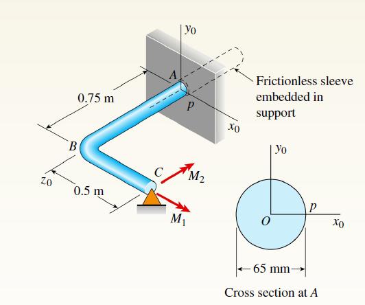
A horizontal bracket ABC consists of two perpendicular arms AB of a length 0.75 m and BC of a length 0.5 m. The bracket has a solid, circular cross section with a diameter equal to 65 mm. The bracket is inserted in a frictionless sleeve at A (which is slightly larger in diameter), so it is free to
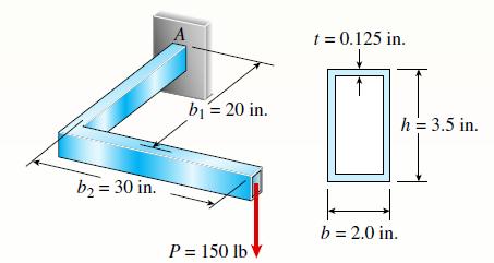
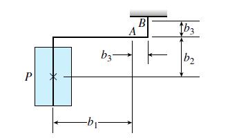
An L-shaped bracket lying in a horizontal plane supports a load P = 150 lb (see figure). The bracket has a hollow rectangular cross section with thickness t = 0.125 in. and outer dimensions b = 2.0 in. and h = 3.5 in. The centerline lengths of the arms are b1 = 20 in. and b2 = 30 in. Considering
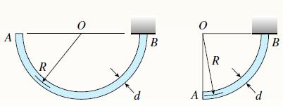
A semicircular bar AB lying in a horizontal plane is supported at B (see figure part a). The bar has a centerline radius R and weight q per unit of length (total weight of the bar equals πqR). The cross-section of the bar is circular with a diameter d.(a) Obtain formulas for the maximum tensile
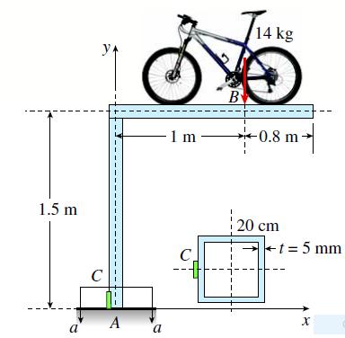
A double-decker bicycle rack made up of square steel tubing is fixed at A (figure a). The weight of a bicycle is represented as a point load applied at B on a plane frame model of the rack (figure b).(a) Find the state of plane stress on element C located on the surface at the left side of the
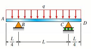
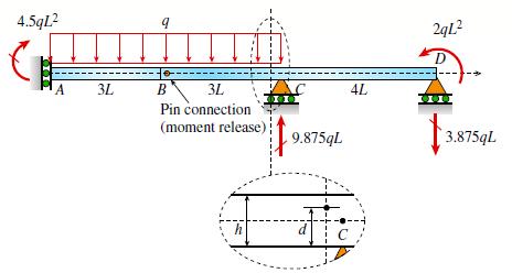
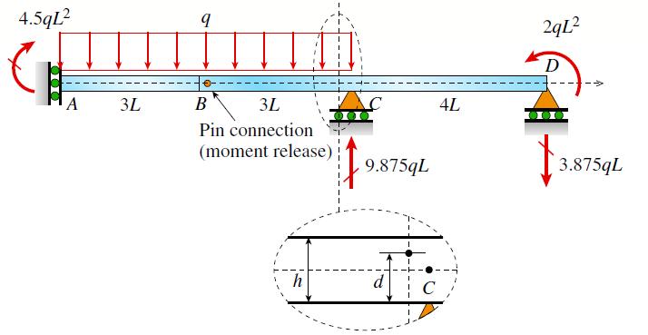
Beam ABCD has sliding support at A, roller supports at C and D, and a pin connection at B (see figure). Assume that the beam has a rectangular cross-section (b = 4 in., h = 12 in.). Uniform load q acts on ABC and a concentrated moment is applied at D. Let load variable q = 1750 lb/ft, and assume
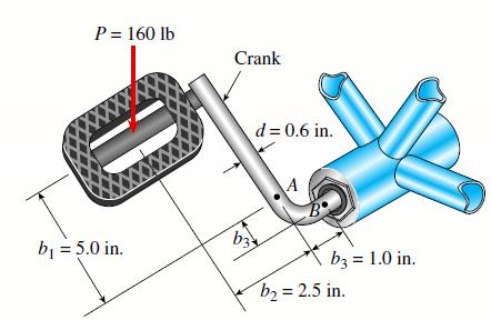
Determine the maximum tensile, compressive, and shear stresses at points A and B on the bicycle pedal crank shown in the figure. The pedal and crank are in a horizontal plane and points A and B are located on the top of the crank. The load P = 160 lb acts in the vertical direction and the distances
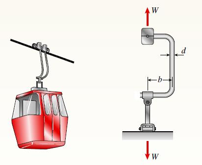
A gondola on a ski lift is supported by two bent arms, as shown in the figure. Each arm is offset by the distance b = 180 mm from the line of action of the weight force W. The allowable stresses in the arms are 100 MPa in tension and 50 MPa in shear. If the loaded gondola weighs 12 kN, what is the
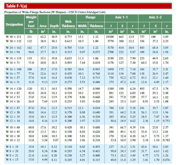
A W 12 X 14 wide-f lange beam (see Table F-1(a), Appendix F) is simply supported with a span length of 120 in. (see figure). The beam supports two anti-symmetrically placed concentrated loads of 7.5 kips each. At a cross section located 20 in. from the righth and support, determine the principal
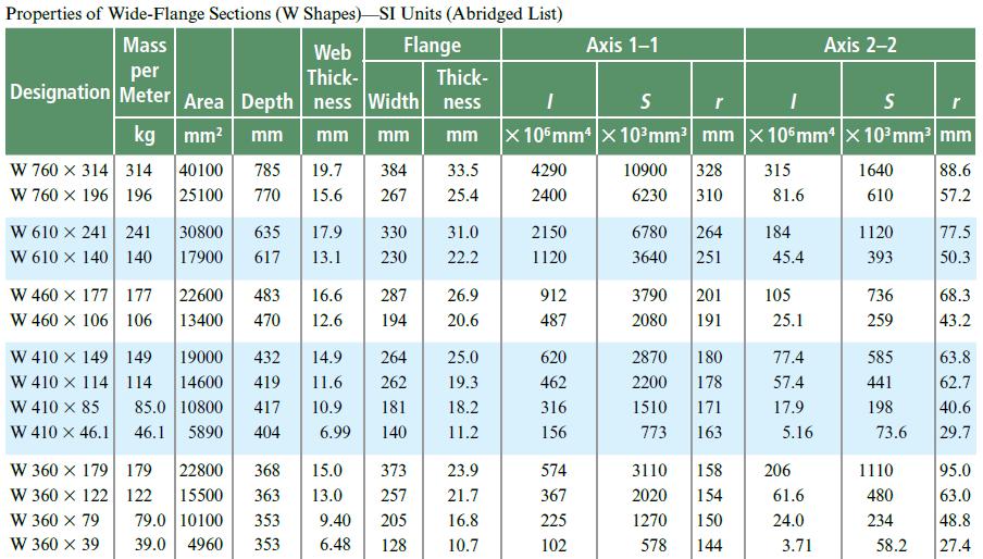
A W 360 X 79 steel beam is fixed at A. The beam has a length of 2.5 m and is subjected to a linearly varying distributed load with maximum intensity q0 = 500 N/m on segment AB and a uniformly distributed load of intensity q0 on segment BC. Calculate the state of plane stress at point D located
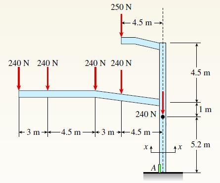
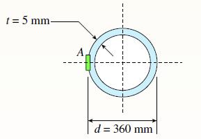
Repeat the preceding problem but now find the stress state on Element A at the base. Let WS = 240 N, WL = 250 N, t = 5 mm, d = 360 mm. See the figure for the locations of element A and all loads. 240 N 240 N TT 250 N -4.5 m 240 N 240 N 240 N -3 m 4.5 m 3 m 4.5 m- x₁ A X 4.5 m [1 m 5.2 m
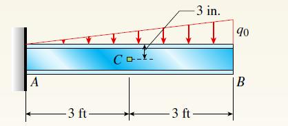
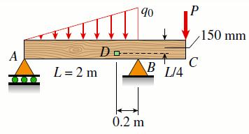
A W 12 X 35 steel beam is fixed at A. The beam has a length L = 6 ft and is subjected to a linearly varying distributed load with peak intensity q0 = 830 lb/ft. Calculate the state of plane stress at point C located 3 in. below the top of the beam at mid-span. Also find the principal normal
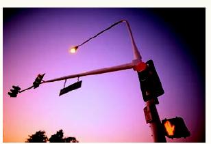
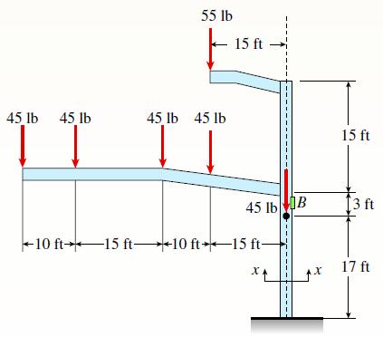
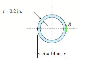
A traffic light and signal pole is subjected to the weight of each traffic signal WS = 45 lb and the weight of the road lamp WL = 55 lb. The pole is fixed at the base. Find the principal normal stresses and the maximum shear stress on element B located 19 ft above the base. Assume that the weight
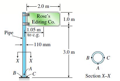
A sign is supported by a pipe having an outer diameter 110 mm and inner diameter 90 mm. The dimensions of the sign are 2.0 m X 1.0 m, and its lower edge is 3.0 m above the base. Note that the center of gravity of the sign is 1.05 m from the axis of the pipe. The wind pressure against the sign is
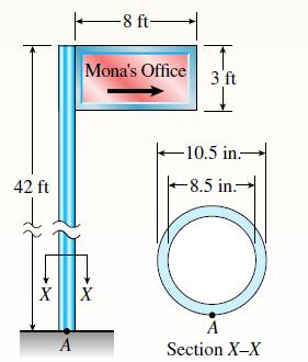
A sign is supported by a pole of hollow circular cross section, as shown in the figure. The outer and inner diameters of the pole are 10.5 in. and 8.5 in., respectively. The pole is 42 ft high and weighs 4 kips. The sign has dimensions 8 ft X 3 ft and weighs 500 lb. Note that its center of gravity
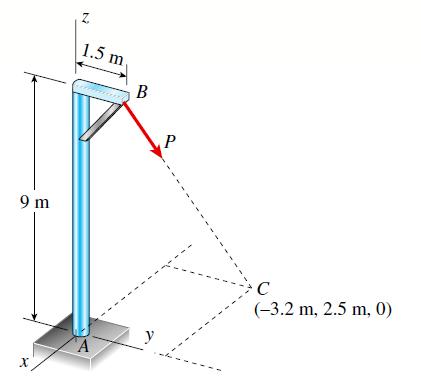
A post having a hollow, circular cross section supports a P = 3.2 kN load acting at the end of an arm that is b = 1.5 m long (see figure). The height of the post is L = 9 m, and its section modulus is S = 2.65 X 105 mm3. Assume that the outer radius of the post is r2 = 123 mm, and the inner radius
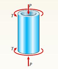
A segment of a generator shaft with a hollow circular cross-section is subjected to a torque T = 240 kip-in. (see figure). The outer and inner diameters of the shaft are 8.0 in. and 6.25 in., respectively. What is the maximum permissible compressive load P that can be applied to the shaft if the
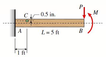
A cantilever beam (width b = 3 in. and depth h = 6 in.) has a length L = 5 ft and is subjected to a point load P and a concentrated moment M = 20 kip-ft at end B. If normal stress σx = 0 at point C, located 0.5 in. below the top of the beam and 1 ft to the right of point A, find point load P.
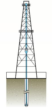
The hollow drill pipe for an oil well (see figure) is 6.2 in. in outer diameter and 0.75 in. in thickness. Just above the bit, the compressive force in the pipe (due to the weight of the pipe) is 62 kips and the torque (due to drilling) is 185 kip-in. Determine the maximum tensile, compressive, and
Beam ABC with an overhang BC is subjected to a linearly varying distributed load on span AB with peak intensity q0 = 2500 N/m and a point load P = 1250 N applied at C. The beam has a width b =100 mm and depth h = 200 mm. Find the state of plane stress at point D located 150 mm below the top of the
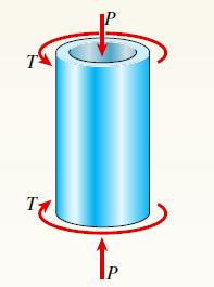
A segment of a generator shaft is subjected to a torque T and an axial force P, as shown in the figure. The shaft is hollow (outer diameter d2 = 300 mm and inner diameter d1 =stress 250 mm) and delivers 1800 kW at 4.0 Hz. If the compressive force P = 540 kN, what are the maximum tensile,
A cantilever wood beam with a width b =100 mm and depth h = 150 mm has a length L = 2 m and is subjected to point load P at mid-span and uniform load q =15 N/m. (a) If the normal stress σx = 0 at point C, located 120 mm below the top of the beam at the fixed support A, calculate the point load P.
The torsional pendulum shown in the figure consists of a horizontal circular disk of a mass M = 60 kg suspended by a vertical steel wire (G = 80 GPa) of a length L = 2 m and diameter d = 4 mm. Calculate the maximum permissible angle of rotation fmax of the disk (that is, the maximum amplitude of
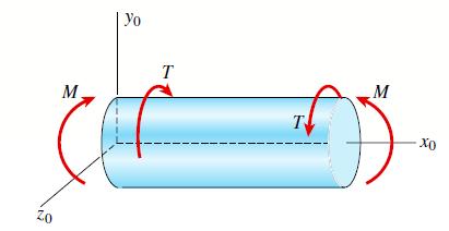
A cylindrical pressure vessel with flat ends is subjected to a torque T and a bending moment M (see figure). The outer radius is 12.0 in. and the wall thickness is 1.0 in. The loads are T = 800 kip-in., M =1000 kip-in., and the internal pressure p = 900 psi. Determine the maximum tensile stress
A pressurized cylindrical tank with flat ends is loaded by torques T and tensile forces P (see figure). The tank has a radius of r = 125 mm and wall thickness t = 6.5 mm. The internal pressure p = 7.25 MPa and the torque T = 850 Nm.(a) What is the maximum permissible value of the forces P if the
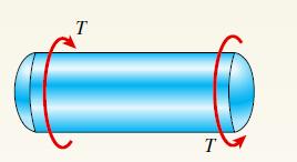
A cylindrical pressure vessel having a radius r =14 in. and wall thickness t = 0.5 in. is subjected to internal pressure p = 375 psi. In addition, a torque T = 90 kip-ft acts at each end of the cylinder (see figure).(a) Determine the maximum tensile stress s max and the maximum in-plane shear
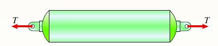
A cylindrical tank having a diameter d = 2.5 in. is subjected to internal gas pressure p = 600 psi and an external tensile load T = 1000 lb (see figure). Determine the minimum thickness t of the wall of the tank based upon allowable shear stress of 3000 psi. T T
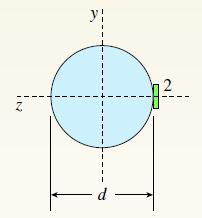
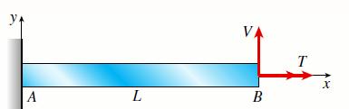
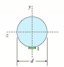
Solve the preceding problem using transverse load V = 300 N and torque T = 3.5 Nm applied at point B. The bar has length L = 1.5 m and diameter d = 8 mm. Calculate the principal stresses and the maximum shear stress for element 2 located at the side of the bar at fixed end A (see figure). Assume
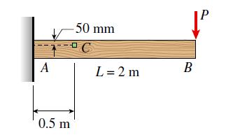
A cantilever beam with a width b =100 mm and depth h = 150 mm has a length L = 2 m and is subjected to a point load P = 500 N at B. Calculate the state of plane stress at point C located 50 mm below the top of the beam and 0.5 m to the right of point A. Also, find the principal stresses and the
A solid circular bar is fixed at point A. The bar is subjected to transverse load V = 70 lb and torque T = 300 lb-in. at point B. The bar has a length L = 60 in. and a diameter d = 3 in. Calculate the principal normal stresses and the maximum shear stress at element 1 located on the bottom surface
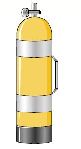
A scuba tank (see figure) is being designed for an internal pressure of 2640 psi with a factor of safety of 2.0 with respect to yield. The yield stress of the steel is 65,000 psi in tension and 32,000 psi in shear.(a) If the diameter of the tank is 7.0 in., what is the minimum required wall
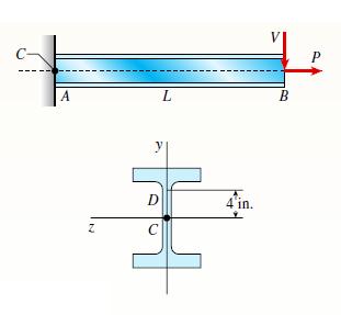
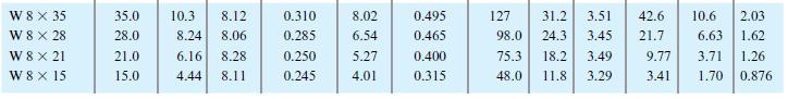
A W 12 x 35 steel cantilever beam is subjected to an axial load P = 10 kips and a transverse load V = 15 kips. The beam has length L = 6 ft. (a) Calculate the principal normal stresses and the maximum shear stress for an element located at C near the fixed support. Neglect the weight of the beam.
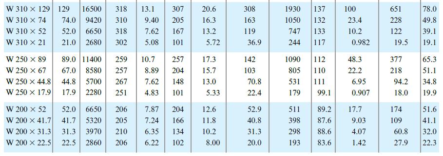
A W 310 x 52 steel beam is subjected to a point load P = 45 kN and a transverse load V = 20 kN at B. The beam has a length L = 2 m. (a) Calculate the principal normal stresses and the maximum shear stress on element D located on the web right below the top flange and near the fixed support. Neglect
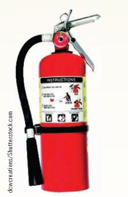
Repeat Problem 8.3-1 for a fire extinguisher tank with an internal pressure of 1.8 MPa, a diameter of 130 mm, and thickness 1.5 mm.Problem 8.3-1A fire extinguisher tank is designed for an internal pressure of 825 psi. The tank has an outer diameter of 4.5 in. and a thickness of 0.08 in. Calculate
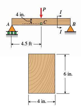
A wood beam with a cross-section 4 x 6 in. is simply supported at A and B. The beam has a length of 9 ft and is subjected to point load P = 5 kips at mid-span. Calculate the state of stress at point C located 4 in. below the top of the beam and 4.5 ft to the right of support A. Neglect the weight
A fire extinguisher tank is designed for an internal pressure of 825 psi. The tank has an outer diameter of 4.5 in. and a thickness of 0.08 in. Calculate the longitudinal stress, the circumferential stress, and the maximum shear stresses (out-of-plane and in-plane) at the outer surface of the tank.
Solve Problem 7.7-14 by using Mohr’s circle for plane strain.Solve the preceding problem for the following strains: Yxy &x=-1120 × 10-6, Ey = -430 × 10-6, = 780 x 10-6, and 0 = 45°.
Solve Problem 7.7-13 by using Mohr’s circle for plane strain.Problem 7.7-13An element of material in plane strain is subjected to strains. Ex 480 × 107 X Ey = = 70 × 10-6, and Y.xv = 420 × 10¯ -6
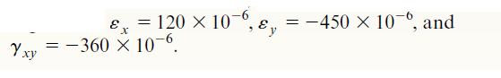
Solve Problem 7.7-12 by using Mohr’s circle for plane strain.Problem 7.7-12Solve the preceding problem for the following strains: Yxy & = 120 × 10-6, y E X =-360 × 10-6. =-450 × 10-6, and
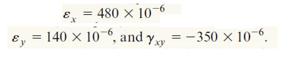
Solve Problem 7.7-11 by using Mohr’s circle for plane strain.Problem 7.7-11The strains for an element of material in plane strain (see figure) are as follows:Determine the principal strains and maximum shear strains, and show these strains on sketches of properly oriented elements. Ex=480 x
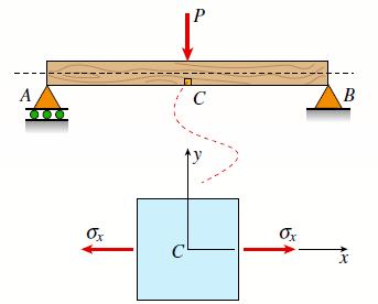
A simply supported wood beam is subjected to point load P at mid-span. The normal stress on the element C is known to be σx = 12 MPa. Find the maximum shear stress on the element and show the state of stress on a sketch of a properly oriented element. A до Ox P с Ox B
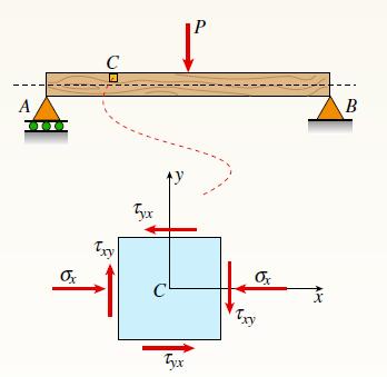
A simply supported wood beam is subjected to point load P at mid-span. The stresses on element C are known to be σx = –92 psi and πxy = –7 psi. Find the principal stresses on the element and show them on a sketch of a properly oriented element. A III Ox C Txy Tyx ТУ Tyx Ox X B
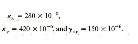
Solve Problem 7.7-9 by using Mohr’s circle for plane strain.Problem 7.7-9An element of material subjected to plane strain (see figure) has strains ofCalculate the strains for an element oriented at an angle u = 358. Show these strains on a sketch of a properly oriented element. Ex Ey = 280 ×
A square plate with side dimension of 2 in, is subjected to compressive stress σx and tensile stress σy. The stresses on element A oriented at angle u = 458 are σx = - 75 psi, σy = - 75 psi, and πxy = - 75 psi. Find the state of stress on the element if it is rotated clockwise to align the x1
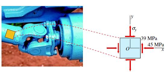
An element in plane stress on the surface of an automobile drive shaft is subjected to stresses of σx = -45 MPa and πxy = 39 MPa. It is known that one of the principal stresses equals 41 MPa in tension.(a) Determine the stress σy.(b) Determine the other principal stress and the orientation of
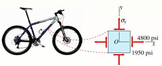
The stresses at a point on the down tube of a bicycle frame are σx = 4800 psi and πxy = –1950 psi. It is known that one of the principal stresses equals 6375 psi in tension.(a) Determine the stress σy.(b) Determine the other principal stress and the orientation of the principal planes, then
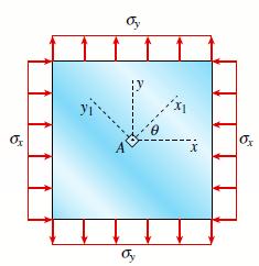
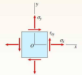
An element in plane stress is subjected to stresses σx, σy, and θxy (see figure). Using Mohr’s circle, determine the stresses acting on an element oriented at an angle u from the x-axis. Show these stresses on a sketch of an element oriented at the angle θ. Ţ y Oy Ţ Txy Ox X
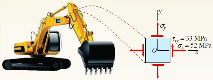
The stresses acting on a stress element on the arm of a power excavator (see figure) are σx = 52 MPa and txy = 33 MPa. What is the allowable range of values for the stress σy if the maximum shear stress is limited to π0 = 37 MPa? P %y = 33 MPa %= 52 MPa Txy
An element in plane stress is subjected to stresses σx, σy, and θxy (see figure). Using Mohr’s circle, determine the stresses acting on an element oriented at an angle u from the x-axis. Show these stresses on a sketch of an element oriented at the angle θ. Ţ y Oy Ţ Txy Ox X
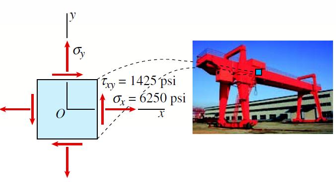
At a point on the web of a girder on a gantry crane, the stresses acting on the x face of a stress element are σx = 6250 psi and πxy = 1425 psi. What is the allowable range of values for the stress σy if the maximum shear stress is limited to t0 = - 150 psi? 0 Oy Ţ Txy = 1425 psi x = 6250 psi X
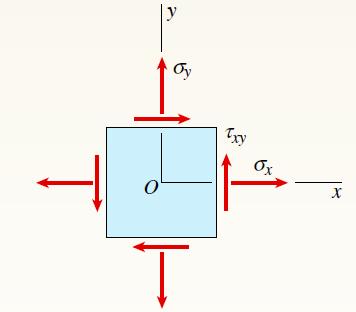
An element in plane stress is subjected to stresses σx, σy, and πxy.(a) Determine the principal stresses and show them on a sketch of a properly oriented element.(b) Determine the maximum shear stresses and associated normal stresses and show them on a sketch of a properly oriented element. σ
The state of stress on an element along the hydraulic lift cylinder on a truck is σy = -5 MPa. Find the maximum shear stress on the element and show the state of stress on a sketch of a properly oriented element.
An element in plane stress is subjected to stresses σx, σy, and πxy.(a) Determine the principal stresses and show them on a sketch of a properly oriented element.(b) Determine the maximum shear stresses and associated normal stresses and show them on a sketch of a properly oriented element. Ox
An element in plane stress is subjected to stresses σx, σy, and θxy (see figure). Using Mohr’s circle, determine the stresses acting on an element oriented at an angle u from the-axis. Show these stresses on a sketch of an element oriented at the angle u. Ţ y Oy Ţ Txy Ox X
An element in plane stress is subjected to stresses σx, σy, and θxy (see figure). Using Mohr’s circle, determine the stresses acting on an element oriented at an angle u from the-axis. Show these stresses on a sketch of an element oriented at the angle θ. Ţ y Oy Ţ Txy Ox X
An element in plane stress is subjected to stresses σx, σy, and θxy (see figure). Using Mohr’s circle, determine the stresses acting on an element oriented at an angle u from the x-axis. Show these stresses on a sketch of an element oriented at the angle θ. Ţ y Oy Ţ Txy Ox X
An element in plane stress is subjected to stresses σx, σy, and πxy.(a) Determine the principal stresses and show them on a sketch of a properly oriented element.(b) Determine the maximum shear stresses and associated normal stresses and show them on a sketch of a properly oriented element.
An element in plane stress is subjected to stresses σx, σy, and θxy. Using Mohr’s circle, determine the stresses acting on an element oriented at an angle u from the -axiss. Show these stresses on a sketch of an element oriented at the angle θ. Ţ y Oy Ţ Txy Ox X
An element in plane stress is subjected to stresses σx, σy, and θxy (see figure). Using Mohr’s circle, determine the stresses acting on an element oriented at an angle u from the x-axis. Show these stresses on a sketch of an element oriented at the angle θ. Ţ y Oy Ţ Txy Ox X
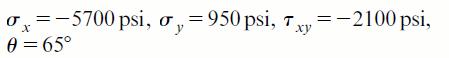
A rubber sheet in biaxial stress is subjected to tensile stresses σx = 270 Pa and σy = 144 Pa. The corresponding strains in the sheet are εx = 0.0002 and εy = 0.000015. Determine Poisson’s ratio and the modulus elasticity of the material. (Courtesy of
An element in plane stress is subjected to stresses σx, σy, and θxy (see figure). Using Mohr’s circle, determine the stresses acting on an element oriented at an angle u from the x-axis. Show these stresses on a sketch of an element oriented at the angle θ. Ţ y Oy Ţ Txy Ox X
Repeat the preceding problem using σy = - 750 psi.
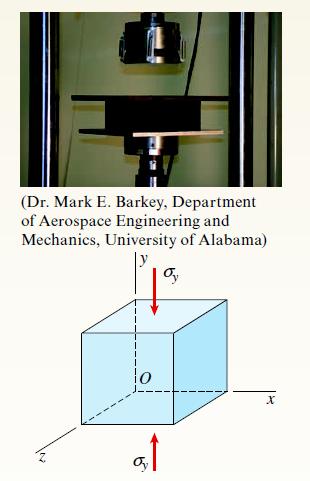
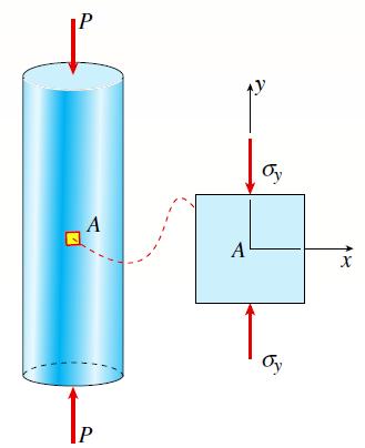
The normal stress on an elastomeric rubber pad in a test machine is σy = -100 psi (see figure). Assume E = 312 psi and shear modulus G =105 psi. (a) Calculate the strains in the pad in the x, y, and z directions.(b) Calculate the unit volume change of the rubber. (Dr. Mark E. Barkey,
An element in plane stress is subjected to stresses σx, σy, and θxy (see figure). Using Mohr’s circle, determine the stresses acting on an element oriented at an angle u from the x-axiss. Show these stresses on a sketch of an element oriented at the angle θ. Ţ y Oy Ţ Txy Ox X
An element in plane stress is subjected to stresses σx, σy, and θxy (see figure). Using Mohr’s circle, determine the stresses acting on an element oriented at an angle u from the x-axis. Show these stresses on a sketch of an element oriented at the angle θ. Ţ y Oy Ţ Txy Ox X
An element in plane stress is subjected to stresses σx, σy, and θxy (see figure). Using Mohr’s circle, determine the stresses acting on an element oriented at an angle u from thex-axiss. Show these stresses on a sketch of an element oriented at the angle u. Ţ y Oy Ţ Txy Ox X
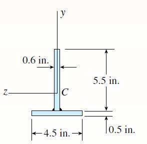
The T-beam shown in the figure is fabricated by welding together two steel plates. If the allowable load for each weld is 1.8 kips/in. in the longitudinal direction, what is the maximum allowable shear force V? N 0.6 in. C ←4.5 in. - 5.5 in. 10.5 in.
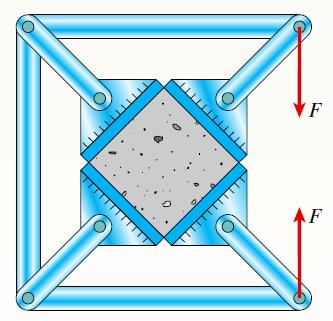
A 4.0 in cube of concrete is compressed in biaxial stress by means of a framework that is loaded as shown in the figure. Assuming that each load F equals 25 kips, determine the change ΔV in the volume of the cube and the strain energy U stored in the cube. F F
A specimen used in a coupon test is shown in the figure. The stresses on element A are known to be σy = -1500 psi. Use Mohr’s circle to:(a) Find the stresses acting on the element oriented at an angle θ = 2358.(b) Find maximum normal and shear stresses and show them on sketches of properly
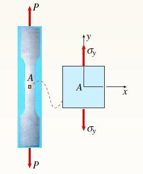
A specimen used in a coupon test has normal stress σy =15 MPa (see figure). Using Mohr’s circle, find the state of stress on the element oriented at angle u = 208 and show the full stress state on a sketch of a properly oriented element. P A P A Oy Oy X
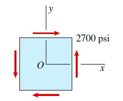
An element on the surface of a drive shaft is in pure shear and is subjected to stresses πxy = 2700 psi, as shown in the figure. Using Mohr’s circle, determine the following.(a) The stresses acting on an element oriented at a counterclockwise angle u = 528 from the-axis.(b) The principal
A cast-iron plate in biaxial stress is subjected to tensile stresses σx = 31MPa and σy = 17 MPa (see figure). The corresponding strains in the plate are Determine Poisson’s ratio n and the modulus of elasticity E for the material. E = 240 X 100 and e = 85 x 10-6
An element of material in plain strain is subjected to strains εx = 0.0015, εy = 20.0002, and Yxy = 0.0003.(a) Determine the strains for an element oriented at an angle u = 2(b) Determine the principal strains of the element. Confirm the solution using Mohr’s circle for plane strain.
An element of a material is subjected to plane stresses as shown in the figure. The stresses σx, σy, and πxy are 10 MPa, –15 MPa, and 5 MPa, respectively. Assume E = 200 GPa and n = 0.3.(a) Calculate the normal strain in the x, y, and z directions and the shear strain.(b) Calculate the
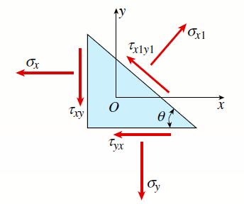
The stresses on an element are known to be σx =120 MPa, σy =100 MPa, and σxy = 75 MPa. Find the stresses on an inclined section through the element at an angle u = 458. Ox 0 Tyx Txlyl et Oy 10x1 X
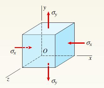
The state of stress on an element of material is shown in the figure. Calculate the unit volume change of the element if the stresses σx and σy are –20 ksi and 10 ksi, respectively. Assume E = 10,600 ksi and v = 0.33. Z Ox 0 Oy Ox X
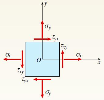
The stresses acting on an element are σx = 750 psi, σy = 600 psi, and πxy = 400 psi. Determine the principal stresses and show them on a sketch of a properly oriented element. Ţ Ox Txy Tyx Ay O бу Ta Tyx Txy Ox X
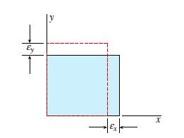
An element of material in plain strain has the following strains: εx = 20.001 and εy = 0.0015.(a) Determine the strains for an element oriented at an angle θ = 258.(b) Find the principal strains of the element.Confirm the solution using Mohr’s circle for plane strain. 후 Ey | 기타 X
Repeat Problem 6.2-1 but now assume that the steel plate is smaller (0.5 in. × 5 in.) and is aligned with the top of the beam as shown in the figure.Problem 6.2-1 A composite beam is constructed using a steel plate (0.5 in X 6 in.) with two wood beams (3 in. X 6 in.) on either side. The wood
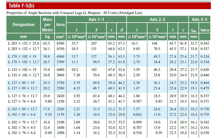
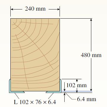
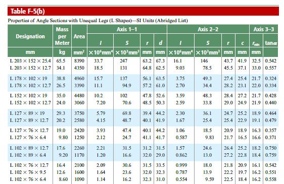
A wood beam in a historic theater is reinforced with two angle sections at the outside lower corners (see figure). If the allowable stress in the wood is 12 MPa and that in the steel is 140 MPa, what is the ratio of the maximum permissible moments for the beam before and after reinforcement with
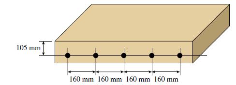
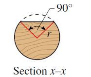
A footbridge on a hiking trail is constructed using two timber logs each having a diameter d = 0.5 m (see figure a). The bridge is simply supported and has a length of L = 4 m. The top of each log is trimmed to form the walking surface (see Fig. b). A simplified model of the bridge is shown in
A wood beam in a historic theater is reinforced with two angle sections at the outside lower corners (see figure). If the allowable stress in the wood is 12 MPa and that in the steel is 140 MPa, what is the ratio of the maximum permissible moments for the beam before and after reinforcement with
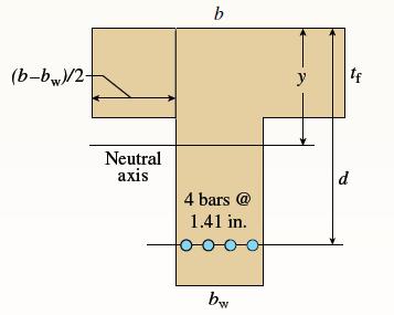
A reinforced concrete T-beam (see figure) is acted on by a positive bending moment of M = 175 kip-ft. Steel reinforcement consists of four bars of 1.41-inch diameter. The modulus of elasticity for the concrete is Ec = 3000 ksi while that of the steel is Es = 29,000 ksi. Let b = 48 in., tf = 4 in.,
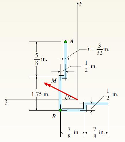
A cold-formed steel section is made by folding a steel plate to form a structural section such as that shown in the figure. This beam is subjected to bending moment M = 2 kip-in. at angle θ = 108 to the z-axis. Find the centroid and the orientation of the neutral axis. Find flexural normal
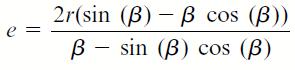
A cross-section in the shape of a circular arc of constant thickness is shown in the figure. Derive the following formula for the distance e from the center of the arc to the shear center S:in which is in radians. Also, plot a graph showing how the distance e varies as varies from 0 to π. 2r(sin
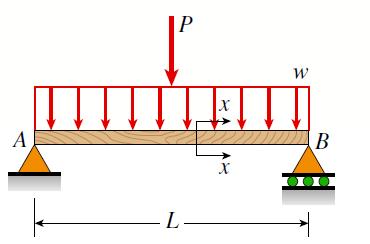
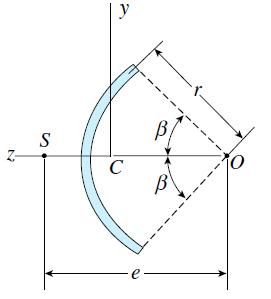
A wood beam AB with a rectangular cross-section (4 in. × 6 in.) serving as a roof purlin is simply supported by the top chords of two adjacent roof trusses. The beam is subjected to distributed load q acting in the vertical direction through the centroid of the purlin cross-section. The top chords
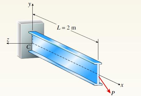
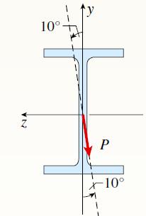
A 2-m-long cantilever beam is constructed using a W 310 × 52 section. Load P acts in an inclined direction at the free end (see figure). Determine the allowable load P that can be carried by the beam if the maximum permissible tensile and compressive stresses are 150 MPa. Include the weight of the
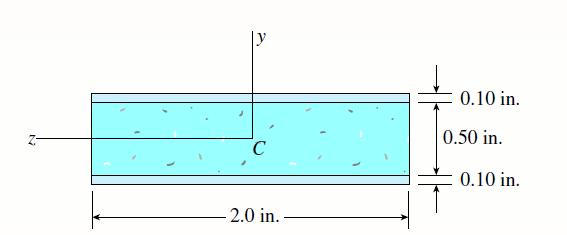
A composite beam consisting of fiberglass faces and a core of particle board has the cross-section shown in the figure. The width of the beam is 2.0 in, the thickness of the faces is 0.10 in., and the thickness of the core is 0.50 in. The beam is subjected to a bending moment of 250 lb-in. acting
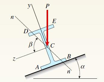
Solve the preceding problem for the following data: b = 6 in., h =10 in., L = 12.0 ft, tan a = 1/3, and q = 325 lb/ft. n В A P E C B n a
A wood beam is strengthened using two steel plates as shown in Fig. a. The beam has simple supports and an overhang and is subjected to a point load and a uniform load as shown in Fig.b. Calculate the maximum tensile and compressive stresses of the beam. Assume that Ew = 11GPa and Es = 200 GPa. 1 2
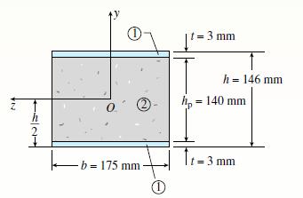
A sandwich beam having steel faces enclosing a plastic core is subjected to a bending moment M = 5 kN · m. The thickness of each steel face is t = 3 mm with a modulus of elasticity Es = 200 GPa. The height of the plastic core is hp =140 mm, and its modulus of elasticity is Ep = 800 MPa. The
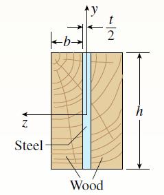
A composite beam is constructed using a steel plate (0.5 in X 6 in.) with two wood beams (3 in. X 6 in.) on either side. The wood and steel are securely fastened to act as a single beam. The beam is subjected to a positive bending moment Mz = 60 kip-in. Calculate the maximum tensile and compressive
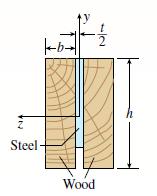
Repeat Problems 6.2-17 but now use a transformed-section approach.Problem 6.2-17Repeat Problem 6.2-1 but now assume that the steel plate is smaller (0.5 in. × 5 in.) and is aligned with the top of the beam as shown in the figure. Steel --b- Wood
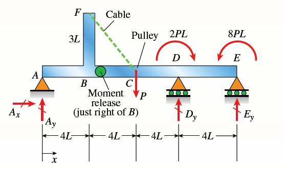
Beam ABCDE has a moment release just right of joint B and has concentrated moment loads at D and E. In addition, a cable with tension P is attached at F and runs over a pulley at C (Fig. a). The beam is constructed using two steel plates, which are welded to form a T cross-section (see Fig. b).
Showing 1300 - 1400
of 1529
First
2
3
4
5
6
7
8
9
10
11
12
13
14
15
16
Step by Step Answers