New Semester
Started
Get
50% OFF
Study Help!
--h --m --s
Claim Now
Question Answers
Textbooks
Find textbooks, questions and answers
Oops, something went wrong!
Change your search query and then try again
S
Books
FREE
Study Help
Expert Questions
Accounting
General Management
Mathematics
Finance
Organizational Behaviour
Law
Physics
Operating System
Management Leadership
Sociology
Programming
Marketing
Database
Computer Network
Economics
Textbooks Solutions
Accounting
Managerial Accounting
Management Leadership
Cost Accounting
Statistics
Business Law
Corporate Finance
Finance
Economics
Auditing
Tutors
Online Tutors
Find a Tutor
Hire a Tutor
Become a Tutor
AI Tutor
AI Study Planner
NEW
Sell Books
Search
Search
Sign In
Register
study help
engineering
mechanics of materials
Mechanics Of Materials 11th Edition Russell C. Hibbeler - Solutions
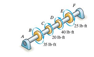
The solid shaft has a diameter of 0.75 in. If it is subjected to the torques shown, determine the maximum shear stress developed in regions CD and EF of the shaft. The bearings at A and F allow free rotation of the shaft. A B E 40 lbft 20 lb-ft 35 lb ft 25 lb-ft
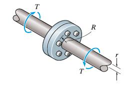
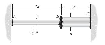
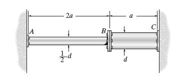
The coupling is used to connect the two shafts together.Assuming that the shear stress in the bolts is uniform, determine the number of bolts necessary to make the maximum shear stress in the shaft equal to the shear stress in the bolts. Each bolt has a diameter d. T
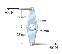
The aluminum tube has an inner diameter of 25 mm and a wall thickness of 5 mm. Determine the maximum shear stress in the fixed tube when the force of 600 N is applied to the cables. Also, sketch the shear stress distribution over the cross section. 600 N 75 mm 5 mm -25 mm 75 mm 600 N
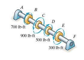
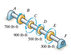
The solid shaft has a diameter of 2 in. If it is subjected to the torques shown, determine the maximum shear stress developed in regions CD and DE of the shaft. The bearings at A and F allow free rotation of the shaft. A B C D 700 lb-ft 900 lb-ft 500 lb-ft 300 lb-ft F
The solid shaft has a diameter of 2 in. If it is subjected to the torques shown, determine the absolute maximum shear stress developed in the shaft. The bearings at A and F allow free rotation of the shaft. A B D E 700 lb-ft 900 lb-ft 500 lb-ft 300 lb-ft F
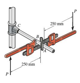
Two wrenches are used to tighten the pipe. If P = 300 N is applied to each wrench, determine the maximum torsional shear stress developed within regions AB and BC. The pipe has an outer diameter of 25 mm and inner diameter of 20 mm. Sketch the shear stress distribution for both cases. P 250 mm B.
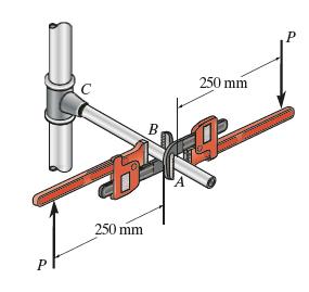
Two wrenches are used to tighten the pipe. If the pipe is made from a material having an allowable shear stress of τallow = 85 MPa, determine the maximum allowable force P that can be applied to each wrench. The pipe has an outer diameter of 25 mm and inner diameter of 20 mm. P 250 mm B 250 mm P
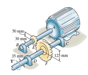
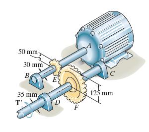
The motor delivers a torque of 50 N m to the shaft AB.This torque is transmitted to shaft CD using the gears at E and F. Determine the equilibrium torque T ′ on shaft CD and the maximum shear stress in each shaft. The bearings B, C, and D allow free rotation of the shafts, and the motor provides
If the applied torque on shaft CD is T' = 75 N m, determine the absolute maximum shear stress in each shaft. The journal bearings B, C, and D allow free rotation of the shafts, and the motor provides a fixed support. 50 mm 30 mm B 125 mm 35 mm T'
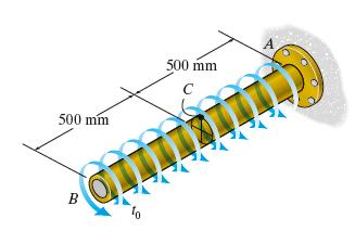
If the tube is subjected to a uniform distributed torque of t0 = 1.2 kN ⋅ m/m, determine the shear stress developed at point C. The inner radius is 20 mm and the outer radius is 30 mm. 500 mm 500 mm C B
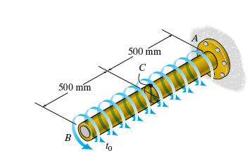
If the tube is subjected to a uniform distributed torque of t0 = 1.2 kN . m m, determine the rod’s minimum required outer radius co and corresponding inner radius ci to the nearest mm if the material has an allowable shear stress of τallow = 80 MPa and ci = 0.9 co. 500 mm 500 mm C B
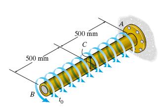
If the tube is made from a material having an allowable shear stress of τallow = 80 MPa, determine the maximum allowable intensity t0 of the uniform distributed torque. The inner radius is 26 mm and the outer radius is 30 mm. 500 mm 500 mm C B
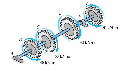
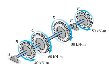
The 160-mm-diameter solid shaft is supported by bearings at A and E. Determine the maximum shear stress developed in each segment of the shaft. B C D A 40 kNm 60 kNm F E 50 kNm 30 kNm
If the tubular shaft is made from material having an allowable shear stress of τallow = 90 MPa, determine the required minimum wall thickess of the shaft to the nearest millimeter. The shaft is supported by bearing at A and E and has an outer diameter of 160 mm. B C D A 40 kNm 60 kNm E 30 kNm 50
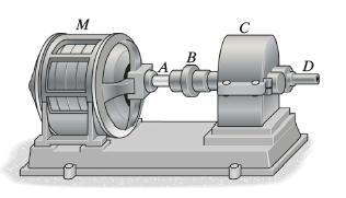
The motor M is connected to the speed reducer C by the tubular shaft and coupling. The shaft has an outer and inner diameter of 1 in. and 0.75 in., respectively, and is made from a material having an allowable shear stress of τallow = 12 ksi, when the motor supplies 20 hp of power. Determine the
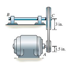
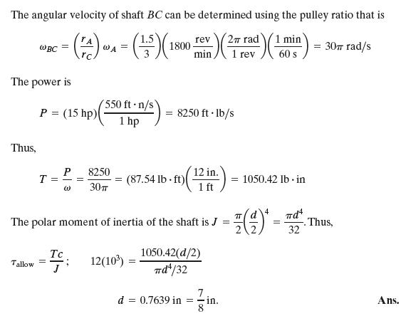
The motor delivers 15 hp to the pulley at A while turning at a constant rate of 1800 rpm. Determine to the nearest 1/8 in. the smallest diameter of shaft BC if the allowable shear stress for steel is τallow = 12 ksi. The belt does not slip on the pulley. B C 3 in. A T1.5 in.
A ship has a propeller drive shaft that is turning at 1500 rev/min while developing 1800 hp. If it is 8 ft long and has a diameter of 4 in., determine the maximum shear stress in the shaft caused by torsion.
The 20-mm-diameter shaft on the motor is made of a material having an allowable shear stress of τallow = 80 MPa.If the motor is operating at its maximum power of 6 kW, determine the minimum allowable rotational speed of the shaft.
The drive shaft of the motor is made of a material having an allowable shear stress of τallow = 80 MPa. If the motor is to deliver a power of 15 kW, determine the required minimum outer diameter and corresponding inner diameter of the tubular shaft to the nearest mm when the shaft is operating at
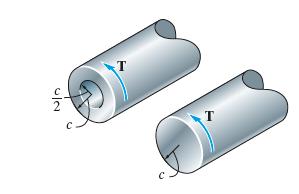
The shaft is subjected to a torque T. Compare the effectiveness of using the tube with that of the solid section of radius c. To do this, calculate the percent increase in torsional stress and angle of twist per unit length for the tube versus the solid section. 20
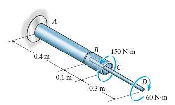
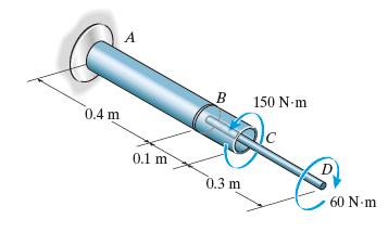
The assembly is made of A-36 steel and consists of a solid rod 20 mm in diameter fixed to the inside of a tube using a rigid disk at B. Determine the angle of twist at D. The tube has an outer diameter of 40 mm and wall thickness of 5 mm. A 0.4 m 0.1 m B 150 N-m 0.3 m 60 N-m
The assembly is made of A-36 steel and consists of a solid rod 20 mm in diameter fixed to the inside of a tube using a rigid disk at B. Determine the angle of twist at C. The tube has an outer diameter of 40 mm and wall thickness of 5 mm. A 0.4 m 0.1 m B 150 N-m 0.3 m 60 Nm
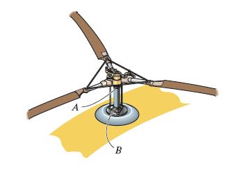
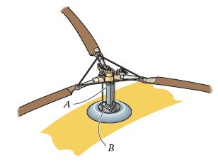
The engine of a helicopter is delivering 600 hp to the rotor shaft AB when the blade is rotating at 1200 rev/min. Determine to the nearest in. the diameter of the shaft AB if the allowable shear stress is τallow = 8 ksi and the angle of twist of the shaft is limited to 0.05 rad. The shaft is 2 ft
The engine of a helicopter is delivering 600 hp to the rotor shaft AB when the blade is rotating at 1200 rev min. Determine to the nearest 1/8 in.the diameter of the shaft AB if the allowable shear stress is τallow = 10.5 ksi and angle of twist of the shaft is limited to 0.05 rad. The shaft is 2
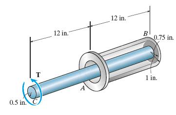
The device serves as a compact torsional spring. It is made of A-36 steel and consists of a solid inner shaft CB which is surrounded by and attached to a tube AB using a rigid ring at B. The ring at A can also be assumed rigid and is fixed from rotating. If a torque of T = 2 kip in. is applied to
The device serves as a compact torsion spring. It is made of A-36 steel and consists of a solid inner shaft CB which is surrounded by and attached to a tube AB using a rigid ring at B. The ring at A can also be assumed rigid and is fixed from rotating. If the allowable shear stress for the material
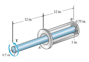
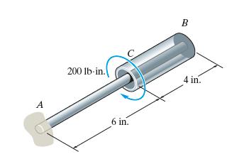
The A-36 steel assembly consists of a tube having an outer radius of 1 in. and a wall thickness of 0.125 in. Using a rigid plate at B, it is connected to the solid 1-in.-diameter shaft AB. Determine the rotation of the tube’s end C if a torque of 200 lb • in. is applied to the tube at this end.
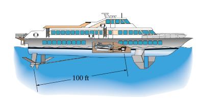
The hydrofoil boat has an A992 steel propeller shaft that is 100 ft long. It is connected to an in-line diesel engine that delivers a maximum power of 2500 hp and causes the shaft to rotate at 1700 rpm. If the outer diameter of the shaft is 8 in. and the wall thickness is 3/8 in., determine the
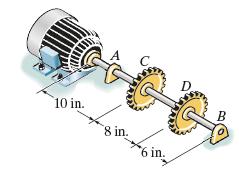
The motor delivers 40 hp to the 304 stainless-steel shaft while it rotates at 20 Hz. The shaft is supported on smooth bearings at A and B, which allow free rotation of the shaft. The gears C and D fixed to the shaft remove 25 hp and 15 hp, respectively. Determine the diameter of the shaft to the
The motor delivers 40 hp to the 304 stainless-steel solid shaft while it rotates at 20 Hz. The shaft has a diameter of 1.5 in. and is supported on smooth bearings at A and B, which allow free rotation of the shaft. The gears C and D fixed to the shaft remove 25 hp and 15 hp, respectively. Determine
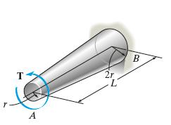
The tapered shaft has a length L and a radius r at end A and 2r at end B. If it is fixed at end B and is subjected to a torque T, determine the angle of twist of end A. The shear modulus is G. T A 2r B
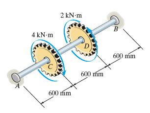
The shaft is made of A-36 steel, has a diameter of 80 mm, and is fixed at B while A is loose and can rotate 0.005 rad before becoming fixed. When the torques are applied to C and D, determine the maximum shear stress in regions AC and CD of the shaft. 4 kNm 2 kNm 600 mm 600 mm B 600 mm
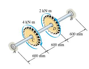
The shaft is made of A-36 steel and has a diameter of 80 mm.It is fixed at B and the support at A has a torsional stiffness of k = 0.5 MN ⋅ m/rad. If it is subjected to the gear torques shown, determine the absolute maximum shear stress in the shaft. 4 kNm 2 kNm 600 mm 600 mm B 600 mm
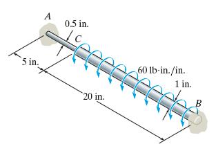
The A-36 steel shaft is made from two segments: AC has a diameter of 0.5 in. and CB has a diameter of 1 in. If the shaft is fixed at its ends A and B and subjected to a uniform distributed torque of 60 lb in./in. along segment CB, determine the absolute maximum shear stress in the shaft. 5 in. A
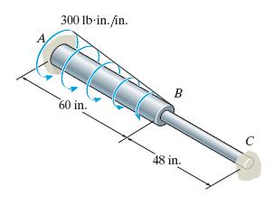
A portion of the A-36 steel shaft is subjected to a linearly distributed torsional loading. If the shaft has the dimensions shown, determine the reactions at the fixed supports A and C. Segment AB has a diameter of 1.5 in. and segment BC has a diameter of 0.75 in. 300 lb-in./in. 60 in. B 48 in. C
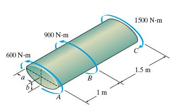
The shaft is made of bronze C86100 and has an elliptical cross section. If it is subjected to the torsional loading shown, determine the maximum shear stress within regions AB and BC, and the angle of twist ϕ of end A. Take a = 80 mm and b = 40 mm. 600 N-m 900 Nm 1500 N-m A B 1 m 1.5 m
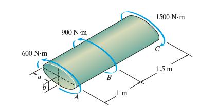
The shaft is made of red brass C83400 and has an elliptical cross section. If the allowable shear stress is τallow = 20 MPa, and the relative angle of twist is limited to 2.50°, determine the dimensions a and b. Take a = 2b. 600 Nm 900 N-m 1500 N-m A B 1 m 1.5 m
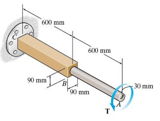
Segments AB and BC of the shaft have circular and square cross sections, respectively. If end A is subjected to a torque of T = 2 kN ⋅ m,, determine the absolute maximum shear stress developed in the shaft and the angle of twist of end A.The shaft is made from A-36 steel and is fixed at C. 600 mm
Segments AB and BC of the shaft have circular and square cross sections, respectively. The shaft is made from A-36 steel with an allowable shear stress of τallow = 75 MPa, and an angle of twist at end A which is not allowed to exceed 0.02 rad. Determine the maximum allowable torque T that can be
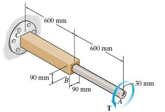
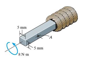
The square shaft is used at the end of a drive cable in order to register the rotation of the cable on a gauge. If it has the dimensions shown and is subjected to a torque of 8 N⋅ m, determine the shear stress in the shaft at point A. Sketch the shear stress on a volume element located at this
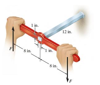
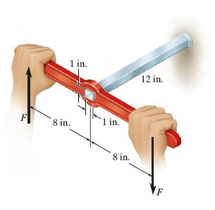
The steel shaft is 12 in. long and is screwed tightly into the wall using a wrench. Determine the largest couple forces F that can be applied to the shaft without causing the steel to yield. Take τy = 8 ksi. 1 in. F 8 in. 1 in. 8 in. 12 in.
The steel shaft is 12 in. long and is screwed tightly into the wall using a wrench. Determine the maximum shear stress in the shaft and the amount of displacement that each couple force undergoes if the couple forces have a magnitude of F =30 lb, Gst =10.8 (103) ksi. 1 in. 8 in.. 1 in. 8 in. 12 in.
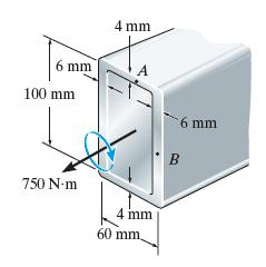
The tube is subjected to a torque of 750 N ⋅ m. Determine the average shear stress in the tube at points A and B. The mean dimensions are shown. 6 mm 100 mm 4 mm 750 N-m 4 mm 60 mm. 6 mm B
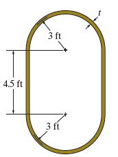
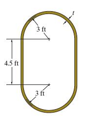
The mean dimensions of the cross section of an airplane fuselage are shown. If the fuselage is made of 2014-T6 aluminum alloy having allowable shear stress of τallow = 18 ksi, and it is subjected to a torque of 6000 kip ft, determine the required minimum thickness t of the cross section to the
The mean dimensions of the cross section of an airplane fuselage are shown. If the fuselage is made from 2014-T6 aluminum alloy having allowable shear stress of Tallow 18 ksi, and the angle of twist per foot length of fuselage is not allowed to exceed 0.001 rad/ft, determine the maximum allowable
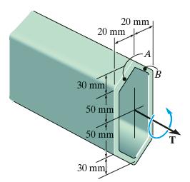
The tube is 5 mm thick and has the mean dimensions shown. Determine the average shear stress at points A and B if the tube is subjected to a torque of T = 500 N ⋅ m. Show the shear stress on volume elements located at these points. Neglect stress concentrations at the corners. 20 mm 20 mm A B 30
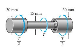
The steel used for the stepped shaft has an allowable shear stress of τallow = 8 MPa. If the radius at the transition between the cross sections is r = 2.25 mm, determine the maximum torque T that can be applied. 30 mm 30 mm 15 mm 7|2 72
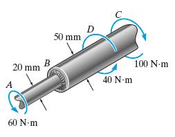
The transition at the cross sections of the stepped shaft has a radius of 2.8 mm. Determine the maximum shear stress developed in the shaft. 20 mm B 50 mm 40 N-m 100 Nm 60 N-m
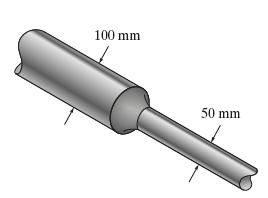
The stepped shaft is to be designed to rotate at 600 rpm while transmitting 60 kW of power. Is this possible if the allowable shear stress is τallow = 60 MPa and the radius at the transition on the shaft is 8.5 mm? 100 mm 50 mm
The built-up shaft is designed to rotate at 720 rpm. If the radius at the transition on the shaft is r = 7.5 mm, and the allowable shear stress for the material is τallow = 60 MPa, determine the maximum power the shaft can transmit. 100 mm 50 mm
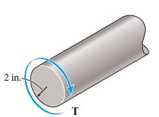
The shaft is made from a strain-hardening material as shown. If the shaft is subjected to a maximum shear strain of 0.0048 rad, determine the torque applied to the shaft. 2 in.- T
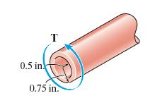
The tubular shaft is made of a strain-hardening material having the τ-γ diagram as shown. Determine the torque T that must be applied to the shaft so that the maximum shear strain is 0.01 rad. T 0.5 in 0.75 in.
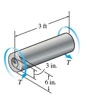
The tube is made of elastic perfectly plastic material, which has the τ-γ diagrams shown. Determine the torque T that just causes the inner surface of the shaft to yield. Also, find the residual shear-stress distribution in the shaft when the torque is removed. 3 ft T 3 in. T 6 in.
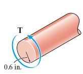
The shaft is made from a strain-hardening material having a τ-γ diagram as shown. Determine the torque T that must be applied to the shaft in order to create an elastic core in the shaft having a radius of pc = 0.5 in. T 0.6 in.
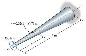
The tapered shaft is made from 2014-T6 aluminum alloy, and has a radius which can be described by the equation r = 0.02(1 + x 3/2) m, where x is in meters. Determine the angle of twist of its end A if it is subjected to a torque of 450 N ⋅ m. r = 0.02(1 + x/2) m 450 N-m 4 m
The assembly consists of an A36 steel rod CB and 2014-T6 aluminum rod BA, each having a diameter of 20 mm. If the rod is subjected to the axial loadings at A and at the coupling B, determine the displacement of the coupling B and the end A.Neglect the size of the connections at B and C, and assume
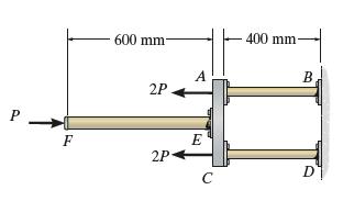
The assembly consists of two 12-mm-diameter A992 steel rods AB and CD, a 20-mm-diameter 6061-T6 aluminum rod EF, and a rigid bar AEC. If P = 20 kN, determine the displacement of end F of rod EF. 600 mm- 2P A 400 mm- B P E F 2P- D C
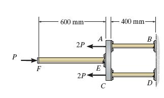
The assembly consists of two 12-mm-diameter A992 steel rods AB and CD, a 20-mm-diameter 6061-T6 aluminum rod EF, and a rigid bar AEC. If the horizontal displacement of end F of rod EF is 0.024 mm, determine the magnitude of P. P F 600 mm- 400 mm- 2P 2P- B E D C
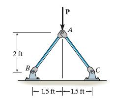
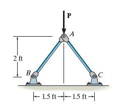
The linkage is made of two pin-connected A-36 steel members, each having a cross-sectional area of 1.5 in2 . If a vertical force of P = 50 kip is applied to joint A, determine the vertical displacement at A. 2 ft I B A 1.5 ft 1.5 ft C
The linkage is made of two pin-connected A-36 steel members, each having a cross-sectional area of 1.5 in2 .Determine the magnitude of the force P needed to displace point A 0.025 in. downward. 2 ft B P A 1.5 ft 1.5 ft C
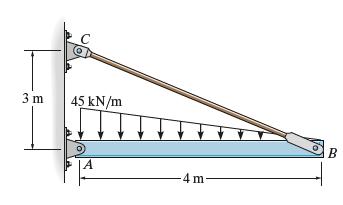
The rigid bar is supported by the pin-connected rod CB that has a cross-sectional area of 500 mm2 and is made of A-36 steel. Determine the vertical displacement of the bar at B when the load is applied. 3 m 45 kN/m A 4 m B
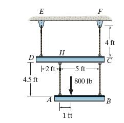
19. The load of 800 lb is supported by the four 304 stainless steel wires that are connected to the rigid members AB and DC. Determine the angle of tilt of each member after the load is applied. The members were originally horizontal, and each wire has a cross-sectional area of 0.05 in2. D E F T 4
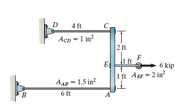
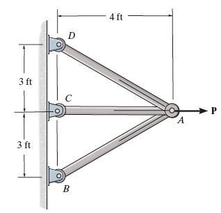
The assembly consists of three titanium (Ti-6A1-4V) rods and a rigid bar AC. The cross-sectional area of each rod is given in the figure. If a force of 6 kip is applied to the ring F, determine the angle of tilt of bar AC. D 4 ft ACD = 1 in AAB = 1.5 in C E 2 ft F 6 kip 1 ft AEF=2 in B 6 ft A
The bar has a length L and cross-sectional area A. Determine its elongation due to the force P and its own weight. The material has a specific weight (weight volume ) and a modulus of elasticity E. L P
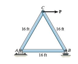
Solve Prob. 4–26 when the load P acts vertically downward at C.Data from Prob. 4–26The truss consists of three members, each made from A-36 steel and having a cross-sectional area of 0.75 in2. Determine the greatest load P that can be applied so that the roller support at B is not displaced
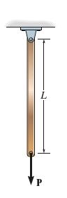
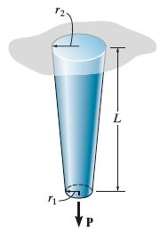
The rod has a slight taper and length L. It is suspended from the ceiling and supports a load P at its end. Show that the displacement of its end due to this load is Neglect the weight of the material. The modulus of elasticity is E. 8=PL/(Er21.
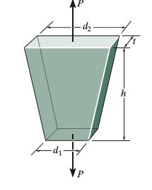
Determine the relative displacement of one end of the tapered plate with respect to the other end when it is subjected to an axial load P. -d- d di P h
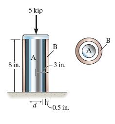
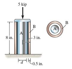
The 304 stainless steel post A has a diameter of d = 2 in. and is surrounded by a red brass C83400 tube B. Both rest on the rigid surface. If a force of 5 kip is applied to the rigid cap, determine the average normal stress developed in the post and the tube. 5 kip 8 in. A B 3 in. B 0.5 in.
The 304 stainless steel post A is surrounded by a red brass C83400 tube B. If a force of 5 kip is applied to the rigid cap, determine the required diameter d of the steel post so that the load is shared equally between the post and tube. 5 kip 8 in. A B 3 in. B 0.5 in.
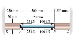
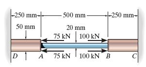
The composite bar consists of a 20-mm-diameter A-36 steel segment AB and 50-mm-diameter red brass C83400 end segments DA and CB. Determine the average normal stress in each segment due to the applied load. -250 mm- 500 mm- -250 mm- 50 mm 20 mm 75 kN 100 kN, A 75 kN 100 kN B
The composite bar consists of a 20-mm-diameter A-36 steel segment AB and 50-mm-diameter red brass C83400 end segments DA and CB. Determine the displacement of A with respect to B due to the applied load. -250 mm- 500 mm- -250 mm- 50 mm 20 mm 75 kN 100 kN, DA 75 kN 100 kN B
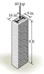
The A-36 steel column, having a cross-sectional area of 18 in2 , is encased in high-strength concrete as shown. If an axial force of 60 kip is applied to the column, determine the average compressive stress in the concrete and in the steel.How far does the column shorten? It has an original length
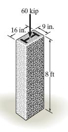
The A-36 steel column is encased in high-strength concrete as shown. If an axial force of 60 kip is applied to the column, determine the required area of the steel so that the force is shared equally between the steel and concrete. How far does the column shorten? It has an original length of 8 ft.
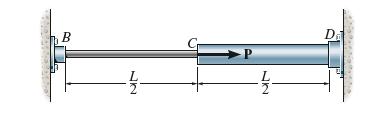
The two pipes are made of the same material and are connected as shown. If the cross-sectional area of BC is A and that of CD is 2A, determine the reactions at B and D when a force P is applied at the junction C. B D
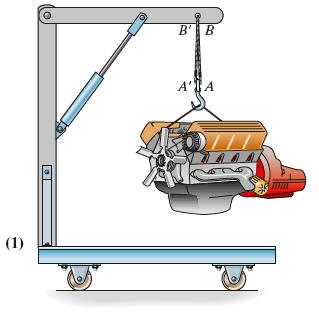
Two A-36 steel wires are used to support the 650-lb engine. Originally, AB is 32 in. long and A′ B′ is 32.008 in. long. Determine the force supported by each wire when the engine is suspended from them. Each wire has a cross-sectional area of 0.01 in2. (1) B' B A' A
The rigid member is held in the position shown by three A-36 steel tie rods. Each rod has a diameter of 20 mm. Determine the forces in the rods if a turnbuckle on rods AB and CD undergoes one and a half revolution. The lead of the screw is 0.9 mm.Neglect the size of the turnbuckle and assume that
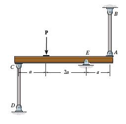
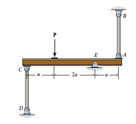
Two identical rods AB and CD each have a length L and diameter d, and are used to support the rigid beam, which is pinned at E. If a vertical force P is applied to the beam, determine the normal stress developed in each rod. The rods are made of material that has a modulus of elasticity of E. P C
Two identical rods AB and CD each have a length L and diameter d, and are used to support the rigid beam, which is pinned at E. If a vertical force P is applied to the beam, determine the angle of rotation of the beam. The rods are made of material that has a modulus of elasticity of E. C D P 2a E
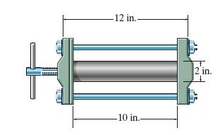
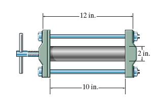
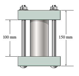
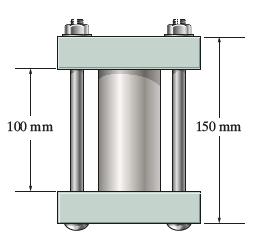
The press consists of two rigid heads that are held together by the two A-36 steel 1/2 -in.-diameter rods. A 6061-T6 solid aluminum cylinder is placed in the press and the screw is adjusted so that it just presses up against the cylinder. If it is then tightened one-half turn, determine the average
The press consists of two rigid heads that are held together by the two A-36 steel 1/2 -in.-diameter rods. A 6061-T6 solid aluminum cylinder is placed in the press and the screw is adjusted so that it just presses up against the cylinder. Determine the angle through which the screw can be turned
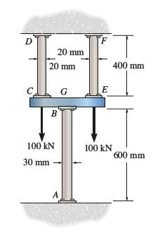
The assembly consists of two 2014-T6 aluminum rods CD and EF of diameter 20 mm, an A992 steel rod AB of diameter 30 mm, and a rigid G. If the supports at A, D, and F are rigid, determine the average normal stress developed in rods AB, CD, and EF. D 20 mm 20 mm C B 400 mm E 100 kN 100 kN 600 mm 30
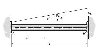
Rod AB has a diameter d and fits snugly between the rigid supports at A and B when it is unloaded. The modulus of elasticity is E. Determine the support reactions at A and B if the rod is subjected to the linearly distributed axial load. p=x L Po -x- L B
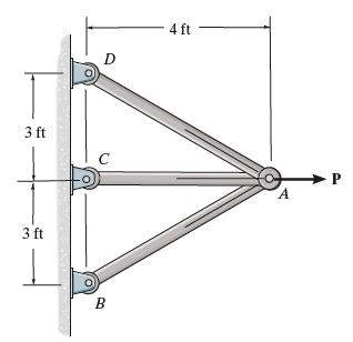
If the 1.5-in.-diameter supporting rods are made from 2014-T6 aluminum, determine the average normal stress developed in each rod when P = 80 kip. D 4 ft 3 ft C A P 3 ft B
If the supporting rods of equal diameter are made from 2014-T6 aluminum, determine the required diameter to the nearest 1/16 in. of each rod when P = 80 kip. The allowable normal stress of the aluminum is σallow = 40 ksi. D 4 ft 3 ft C A P 3 ft B
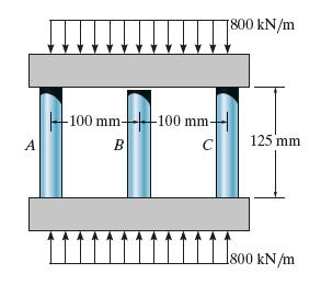
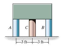
The center post B of the assembly has an original length of 124.7 mm, whereas posts A and C have a length of 125 mm. If the caps on the top and bottom can be considered rigid, determine the average normal stress in each post. The posts are made of aluminum and have a cross-sectional area of 400
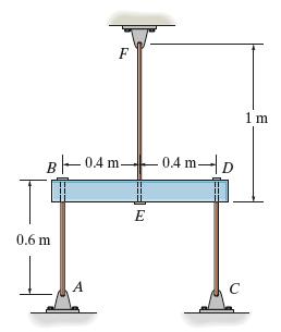
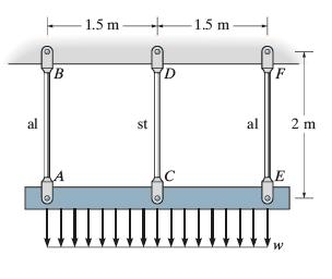
The distributed loading is supported by the three suspender bars. AB and EF are made of aluminum and CD is made of steel. If each bar has a cross-sectional area of 450 mm2, determine the maximum intensity w of the distributed loading so that an allowable stress of ( σallow)st = 180 MPa in the
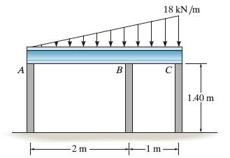
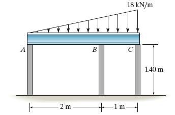
The horizontal beam is assumed to be rigid and supports the distributed load shown. Determine the vertical reactions at the supports. Each support consists of a wooden post having a diameter of 120 mm and an unloaded (original) length of 1.40 m. Take EW = 12 GPa. 18 kN/m B C A -2 m +1m -1 m 1.40 m
The horizontal beam is assumed to be rigid and supports the distributed load shown. Determine the angle of tilt of the beam after the load is applied. Each support consists of a wooden post having a diameter of 120 mm and an unloaded(original) length of 1.40 m. Take Ew = 12 GPa. A B 18 kN/m C F -2
If the assembly fits snugly between two rigid supports A and C when the temperature is at T1 , determine the normal stress developed in both segments when the temperature rises to T2. Both solid segments are made of the same material, having a modulus of elasticity of E and coefficient of thermal
If the assembly fits snugly between the two supports A and C when the temperature is T1 , determine the normal stress developed in both segments when the temperature rises to T2. Both segments are made of the same material having a modulus of elasticity of E and coefficient of thermal expansion of
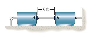
A 6-ft-long steam pipe is made of A-36 steel with σy = 40 ksi. It is connected directly to two turbines A and B as shown. The pipe has an outer diameter of 4 in. and a wall thickness of 0.25 in. The connection was made when T1 = 70°F. If the turbines' points of attachment are assumed rigid,
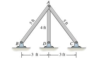
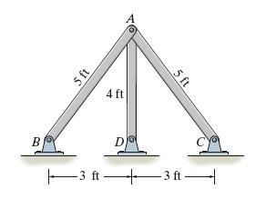
The three bars are made of A-36 steel and form a pin-connected truss. If the truss is constructed when T1 = 50°F, determine the force in each bar when T2 = 110°F. Each bar has a cross-sectional area of 2 in2. B 5 ft 4 ft 5 ft 3 ft 3 ft
The three bars are made of A-36 steel and form a pinconnected truss. If the truss is constructed when T1 = 50°F, determine the vertical displacement of joint A when T2 = 150°F. Each bar has a cross-sectional area of 2 in2. B 5 ft 4 ft 5 ft D 3 ft 3 ft
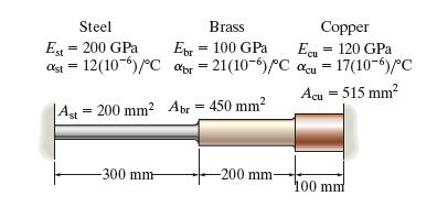
Three bars, each made of different materials, are connected together and placed between two walls when the temperature is T1 = 12°C. Determine the force exerted on the (rigid) supports when the temperature becomes T2 = 18°C. The material properties and cross-sectional area of each bar are given
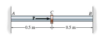
The A-36 steel rod has a diameter of 50 mm and is lightly attached to the rigid supports at A and B when T1 = 80°C. If the temperature becomes T2 = 20°C and an axial force of P = 200 kN is applied to its center, determine the reactions at A and B. A P -0.5 m + 0.5 m- B
The A-36 steel rod has a diameter of 50 mm and is lightly attached to the rigid supports at A and B when T1 = 50°C.Determine the force P that must be applied to the collar at its midpoint so that, when T2 = 30°C, the reaction at B is zero. A -0.5 m- C 0.5 m B
The 50-mm-diameter cylinder is made from Am 1004-T61 magnesium and is placed in the clamp when the temperature is T1= 20C. If the 304-stainless-steel carriage bolts of the clamp each have a diameter of 10 mm, and they hold the cylinder snug with negligible force against the rigid jaws, determine
The 50-mm-diameter cylinder is made from Am 1004-T61 magnesium and is placed in the clamp when the temperature is T1 = 15°C. If the two 304-stainless-steel carriage bolts of the clamp each have a diameter of 10 mm, and they hold the cylinder snug with negligible force against the rigid jaws,
The rigid block has a weight of 80 kip and is to be supported by posts A and B, which are made of A-36 steel, and the post C, which is made of C83400 red brass. If all the posts have the same original length before they are loaded, determine the average normal stress developed in each post when
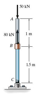
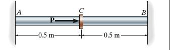
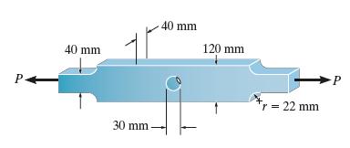
Determine the maximum axial force P that can be applied so as not to exceed an allowable tensile stress ofσ allow = 200 MPa. P 40 mm 40 mm 120 mm 30 mm += 22 mm P
Showing 1100 - 1200
of 1529
First
2
3
4
5
6
7
8
9
10
11
12
13
14
15
16
Step by Step Answers