New Semester
Started
Get
50% OFF
Study Help!
--h --m --s
Claim Now
Question Answers
Textbooks
Find textbooks, questions and answers
Oops, something went wrong!
Change your search query and then try again
S
Books
FREE
Study Help
Expert Questions
Accounting
General Management
Mathematics
Finance
Organizational Behaviour
Law
Physics
Operating System
Management Leadership
Sociology
Programming
Marketing
Database
Computer Network
Economics
Textbooks Solutions
Accounting
Managerial Accounting
Management Leadership
Cost Accounting
Statistics
Business Law
Corporate Finance
Finance
Economics
Auditing
Tutors
Online Tutors
Find a Tutor
Hire a Tutor
Become a Tutor
AI Tutor
AI Study Planner
NEW
Sell Books
Search
Search
Sign In
Register
study help
physics
physics scientists and engineers
Physics for Scientists and Engineers A Strategic Approach with Modern Physics 4th edition Randall D. Knight - Solutions
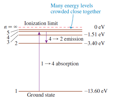
What is the third-longest wavelength in the absorption spectrum of hydrogen?
In a photoelectric-effect experiment, the wavelength of light shining on an aluminum cathode is decreased from 250 nm to 200 nm. What is the change in the stopping potential?
A ruby laser emits an intense pulse of light that lasts a mere 10 ns. The light has a wavelength of 690 nm, and each pulse has an energy of 500 mJ.a. How many photons are emitted in each pulse?b. What is the rate of photon emission, in photons per second, during the 10 ns that the laser is “on”?
The wavelengths of light emitted by a firefly span the visible spectrum but have maximum intensity near 550 nm. A typical flash lasts for 100 ms and has a power output of 1.2 mW. How many photons does a firefly emit in one flash if we assume that all light is emitted at the peak intensity
Dinoflagellates are single-cell organisms that float in the world’s oceans. Many types are bioluminescent. When disturbed, a typical bioluminescent dinoflagellate emits 108 photons in a 0.10-s-long flash of wavelength 460 nm. What is the power of the flash?
In a photoelectric-effect experiment, the stopping potential was measured for several different wavelengths of incident light. The data are as follows:Wavelength (nm)..................Stopping potential
The maximum kinetic energy of photoelectrons is 2.8 eV. When the wavelength of the light is increased by 50%, the maximum energy decreases to 1.1 eV. What are (a) The work function of the cathode (b) The initial wavelength of the light?
Potassium and gold cathodes are used in a photoelectric effect experiment. For each cathode, find:a. The threshold frequency.b. The threshold wavelength.c. The maximum photoelectron ejection speed if the light has a wavelength of 220 nm.d. The stopping potential if the wavelength is 220 nm.
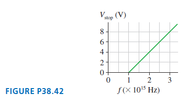
The graph in FIGURE P38.42 was measured in a photoelectric effect experiment. a. What is the work function (in eV) of the cathode?b. What experimental value of Planck??s constant is obtained from these data? stop (V) 8 4 2- 0+ 1 2 3 FIGURE P38.42 f(X 1015 Hz)
A 75 kW radio transmitter emits 550 kHz radio waves uniformly in all directions. At what rate do photons strike a 1.5-m-tall, 3.0-mm-diameter antenna that is 15 km away?
The cosmic microwave background radiation is light left over from the Big Bang that has been Doppler-shifted to microwave frequencies by the expansion of the universe. It now fills the universe with 450 photons/cm3 at an average frequency of 160 GHz. How much energy from the cosmic microwave
The electron interference pattern of Figure 38.12 was made by shooting electrons with 50 keV of kinetic energy through two slits spaced 1.0 μm apart. The fringes were recorded on a detector 1.0 m behind the slits.a. What was the speed of the electrons? (The speed is large enough to
Electrons, all with the same speed, pass through a tiny 15 nm-wide slit and create a diffraction pattern on a detector 50 mm behind the slit. What is the electron’s kinetic energy, in eV, if the central maximum has a width of 3.3 mm?
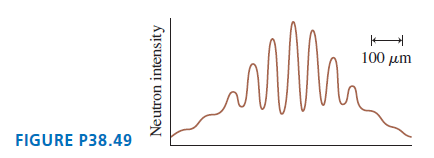
An experiment was performed in which neutrons were shot through two slits spaced 0.10 mm apart and detected 3.5 m behind the slits. FIGURE P38.49 shows the detector output. Notice the 100 μm scale on the figure. To one significant figure, what was the speed of the neutrons? 100 µm
An electron confined in a one-dimensional box is observed, at different times, to have energies of 12 eV, 27 eV, and 48 eV. What is the length of the box?
A muon—a subatomic particle with charge -e and a mass 207 times that of an electron—is confined in a 15-pm-long, one-dimensional box. (1 pm = 1 picometer = 10-12 m.) What is the wavelength, in nm, of the photon emitted in a quantum jump from n = 2 to n = 1?
An electron confined in a one-dimensional box emits a 200 nm photon in a quantum jump from n = 2 to n = 1. What is the length of the box?
Consider a small virus having a diameter of 10 nm. The atoms of the intracellular fluid are confined within the virus. Suppose we model the virus as a 10-nm-long “box.” What is the ground state energy (in eV) of a sodium ion confined in this box?
The absorption spectrum of an atom consists of the wavelengths 200 nm, 300 nm, and 500 nm.a. Draw the atom’s energy-level diagram.b. What wavelengths are seen in the atom’s emission spectrum?
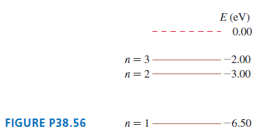
The first three energy levels of the fictitious element X are shown in FIGURE P38.56. a. What is the ionization energy of element X?b. What wavelengths are observed in the absorption spectrum of element X? Express your answers in nm.c. State whether each of your wavelengths in part b corresponds
The first three energy levels of the fictitious element X were shown in FIGURE P38.56. An electron with a speed of 1.4 × 10⁶m/s collides with an atom of element X. Shortly afterward, the atom emits a photon with a wavelength of 1240 nm. What was the electron??s speed after the collision? Assume
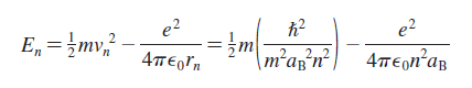
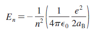
Starting from Equation 38.32, derive Equation 38.33.Equation 38.32Equation 38.33 e2 = }m| 4περΤη e2 \m²a;? 4περηap E, =mv, 2,2 m'авn- e? 2ав En n 1 4περ 2a 4те
An electron with a speed of 2.1 × 10⁶ m/s collides with a hydrogen atom, exciting the atom to the highest possible energy level. The atom then undergoes a quantum jump with Δn = 1. What is the wavelength of the photon emitted in the quantum jump?
a. What wavelength photon does a hydrogen atom emit in a 200 → 199 transition?b. What is the difference in the wavelengths emitted in a 199 → 2 transition and a 200 → 2 transition?
Consider a hydrogen atom in stationary state n.a. Show that the orbital period of an electron in quantum state n is T = n3T1, and find a numerical value for T1.b. On average, an atom stays in the n = 2 state for 1.6 ns before undergoing a quantum jump to the n = 1 state. On average, how many
Draw an energy-level diagram, similar toFigure 38.21, for the He+ion. On your diagram:a. Show the first five energy levels. Label each with the values of n and En.b. Show the ionization limit.c. Show all possible emission transitions from the n = 4 energy level.d. Calculate the wavelengths (in nm)
The muon is a subatomic particle with the same charge as an electron but with a mass that is 207 times greater: mμ = 207me. Physicists think of muons as “heavy electrons.” However, the muon is not a stable particle; it decays with a half-life of 1.5 μs into an electron plus two neutrinos.
Two hydrogen atoms collide head-on. The collision brings both atoms to a halt. Immediately after the collision, both atoms emit a 121.6 nm photon. What was the speed of each atom just before the collision?
A beam of electrons is incident upon a gas of hydrogen atoms.a. What minimum speed must the electrons have to cause the emission of 656 nm light from the 3 → 2 transition of hydrogen?b. Through what potential difference must the electrons be accelerated to have this speed?
The electrons in a cathode-ray tube are accelerated through a 250 V potential difference and then shot through a 33-nm diameter circular aperture. What is the diameter of the bright spot on an electron detector 1.5 m behind the aperture?
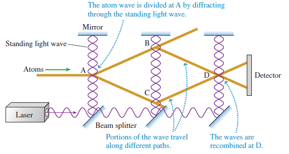
In the atom interferometer experiment ofFigure 38.13, lasercooling techniques were used to cool a dilute vapor of sodium atoms to a temperature of 0.0010 K = 1.0 mK. The ultracold atoms passed through a series of collimating apertures to form the atomic beam you see entering the figure from the
Consider an electron undergoing cyclotron motion in a magnetic field. According to Bohr, the electron’s angular momentum must be quantized in units of ℏ.a. Show that allowed radii for the electron’s orbit are given by rn = (nℏ/eB)1/2, where n = 1, 2, 3, ….b. Compute the first four allowed
What are the wavelengths of spectral lines in the Balmer series with n = 6, 8, and 10?
a. Summarize the experimental evidence prior to the research of Thomson by which you might conclude that cathode rays are some kind of particle.b. Summarize the experimental evidence prior to the research of Thomson by which you might conclude that cathode rays are some kind of wave.
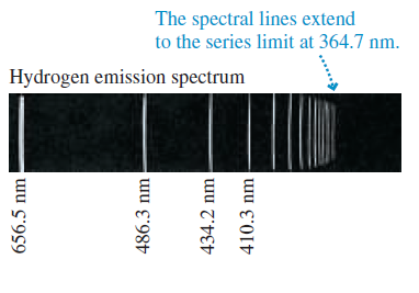
Figure 37.7 identified the wavelengths of four lines in the Balmer series of hydrogen.a. Determine the Balmer formula n and m values for these wavelengths.b. Predict the wavelength of the fifth line in the spectrum. The spectral lines extend to the series limit at 364.7 nm. Hydrogen emission
Thomson observed deflection of the cathode-ray particles due to magnetic and electric fields, but there was no observed deflection due to gravity. Why not?
The wavelengths in the hydrogen spectrum with m = 1 form a series of spectral lines called the Lyman series. Calculate the wavelengths of the first four members of the Lyman series.
What was the significance of Thomson’s experiment in which an off-center electrode was used to collect charge deflected by a magnetic field?
Two of the wavelengths emitted by a hydrogen atom are 102.6 nm and 1876 nm.a. What are the m and n values for each of these wavelengths?b. For each of these wavelengths, is the light infrared, visible, or ultraviolet?
What is the evidence by which we know that an electron from an iron atom is identical to an electron from a copper atom?
A 2.0-cm-diameter metal sphere is glowing red, but a spectrum shows that its emission spectrum peaks at an infrared wavelength of 2.0 μm. How much power does the sphere radiate? Assume e = 1.
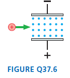
FIGURE Q37.6 shows a magnetic field between two parallel, charged electrodes. An electron with speed v0?passes between the plates, from left to right, with no deflection. If a proton is fired toward the plates with the same speed v0, will it be deflected up, deflected down, or pass through with no
What temperature, in °C, is a blackbody whose emission spectrum peaks at(a) 300 nm(b) 3.00 mm?
a. Describe the experimental evidence by which we know that the nucleus is made up not just of protons.b. The neutron is not easy to isolate or control because it has no charge that would allow scientists to manipulate it. What evidence allowed scientists to determine that the mass of the neutron
A ceramic cube 3.0 cm on each side radiates heat at 630 W. At what wavelength, in mm, does its emission spectrum peak? Assume e = 1.
Rutherford studied alpha particles using the crossed-field technique Thomson had invented to study cathode rays. Assuming that valpha ≈ vcathode ray (which turns out to be true), would the deflection of an alpha particle by a magnetic field be larger than, smaller than, or the same as the
The current in a Crookes tube is 10 nA. How many electrons strike the face of the glass tube each second?
Once Thomson showed that atoms consist of very light negative electrons and a much more massive positive charge, why didn’t physicists immediately consider a solar system model of electrons orbiting a positive nucleus? Why would physicists in 1900 object to such a model?
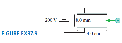
Electrons pass through the parallel electrodes shown in FIGURE EX37.9 with a speed of 5.0 × 10⁶m/s. What magnetic field strength and direction will allow the electrons to pass through without being deflected? Assume that the magnetic field is confined to the region between the electrodes. + 200 V
An electron in a cathode-ray beam passes between 2.5 cm-long parallel-plate electrodes that are 5.0 mm apart. A 2.0 mT, 2.5-cm-wide magnetic field is perpendicular to the electric field between the plates. The electron passes through the electrodes without being deflected if the potential
An alpha particle (a bare helium nucleus with q = +2e) accelerates across a 100 V potential difference, starting from rest. What is the particle’s kinetic energy in eV when it reaches the negative electrode? This question requires no mathematics beyond what you can do in your head.
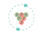
Identify the element, the isotope, and the charge state of each atom in FIGURE Q37.12. Give your answer in symbolic form, such as4He+or8Be-. a. b. n Pn n P. (P
A 0.80-μm-diameter oil droplet is observed between two parallel electrodes spaced 11 mm apart. The droplet hangs motionless if the upper electrode is 20 V more positive than the lower electrode. The density of the oil is 885 kg/m3.a. What is the droplet’s mass?b. What is the droplet’s
Suppose that in a hypothetical oil-drop experiment you measure the following values for the charges on the drops: 3.99 × 10⁻¹⁹ C, 6.65 × 10⁻¹⁹ C, 2.66 × 10⁻¹⁹ C, 10.64 × 10⁻¹⁹ C, and 9.31 × 10⁻¹⁹ C. What is the largest value of the fundamental unit of charge that is consistent with your
Determine:a. The speed of a 7.0 MeV neutron.b. The speed of a 15 MeV helium atom.c. The specific type of particle that has 1.14 keV of kinetic energy when moving with a speed of 2.0 × 10⁷ m/s.
Determine:a. The speed of a 300 eV electron.b. The speed of a 3.5 MeV H+ ion.c. The specific type of particle that has 2.09 MeV of kinetic energy when moving with a speed of 1.0 × 10⁷ m/s.
Express in eV (or keV or MeV if more appropriate):a. The kinetic energy of a Li++ ion that has accelerated from rest through a potential difference of 5000 V.b. The potential energy of two protons 10 fm apart.c. The kinetic energy, just before impact, of a 200 g ball dropped from a height of 1.0 m.
Express in eV (or keV or MeV if more appropriate):a. The kinetic energy of an electron moving with a speed of 5.0 × 10⁶ m/s.b. The potential energy of an electron and a proton 0.10 nm apart.c. The kinetic energy of a proton that has accelerated from rest through a potential difference of 5000 V.
A parallel-plate capacitor with a 1.0 mm plate separation is charged to 75 V. With what kinetic energy, in eV, must a proton be launched from the negative plate if it is just barely able to reach the positive plate?
How many electrons, protons, and neutrons are contained in the following atoms or ions:(a) 10B,(b) 13N+,(c) 17O+++?
Identify the isotope that is 11 times as heavy as 12C and has 18 times as many protons as 6Li. Give your answer in the form AS, where S is the symbol for the element.
Write the symbol for an atom or ion with:a. five electrons, five protons, and six neutrons.b. five electrons, six protons, and eight neutrons.
Consider the gold isotope 197Au.a. How many electrons, protons, and neutrons are in a neutral 197Au atom?b. The gold nucleus has a diameter of 14.0 fm. What is the density of matter in a gold nucleus?c. The density of lead is 11,400 kg/m3. How many times the density of lead is your answer to part b?
Consider the lead isotope 207Pb.a. How many electrons, protons, and neutrons are in a neutral 207Pb atom?b. The lead nucleus has a diameter of 14.2 fm. What is the electric field strength at the surface of a lead nucleus?
What is the total energy, in MeV, ofa. A proton traveling at 99% of the speed of light?b. An electron traveling at 99% of the speed of light?
What is the velocity, as a fraction of c, ofa. A proton with 500 GeV total energy?b. An electron with 2.0 GeV total energy?
The Large Hadron Collider accelerates two beams of protons, which travel around the collider in opposite directions, to a total energy of 6.5 TeV per proton. (1 TeV = 1 teraelectron volt = 1012 eV.) The beams cross at several points, and a few protons undergo headon collisions. Such collisions
The Large Hadron Collider accelerates protons to a total energy of 6.5 TeV per proton. (1 TeV = 1 teraelectron volt = 1012 eV.) What is the speed of a proton that has this energy? Give your answer as fraction of c, using as many significant figures as needed.
You learned in Chapter 36 that mass has an equivalent amount of energy. What are the energy equivalents in MeV of the rest masses of an electron and a proton?
The factor g appears in many relativistic expressions. A value γ = 1.01 implies that relativity changes the Newtonian values by approximately 1% and that relativistic effects can no longer be ignored. At what kinetic energy, in MeV, is γ = 1.01 for(a) An electron,(b) A proton,(c) An alpha
An electron in a cathode-ray beam passes between 2.5-cm-long parallel-plate electrodes that are 5.0 mm apart. A 1.0 mT, 2.5-cm-wide magnetic field is perpendicular to the electric field between the plates. If the potential difference between the plates is 150 V, the electron passes through the
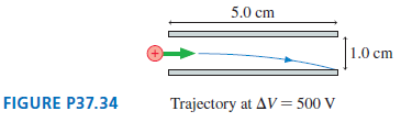
The two 5.0-cm-long parallel electrodes in FIGURE P37.34 are spaced 1.0 cm apart. A proton enters the plates from one end, an equal distance from both electrodes. A potential difference ΔV = 500 V across the electrodes deflects the proton so that it strikes the outer end of the lower electrode.
An unknown charged particle passes without deflection through crossed electric and magnetic fields of strengths 187,500 V/m and 0.1250 T, respectively. The particle passes out of the electric field, but the magnetic field continues, and the particle makes a semicircle of diameter 25.05 cm. What is
In one of Thomson’s experiments he placed a thin metal foil in the electron beam and measured its temperature rise. Consider a cathode-ray tube in which electrons are accelerated through a 2000 V potential difference, then strike a 10 mg copper foil. What is the electron-beam current if the foil
A neutral lithium atom has three electrons. As you will discover in Chapter 41, two of these electrons form an “inner core,” but the third—the valence electron—orbits at much larger radius. From the valence electron’s perspective, it is orbiting a spherical ball of charge having net
A hydrogen atom 1H with 200 eV of kinetic energy has a headon, perfectly elastic collision with a 12C atom at rest. Afterward, what is the kinetic energy, in eV, of each atom?
The diameter of an atom is 1.2 × 10⁻¹⁰ m and the diameter of its nucleus is 1.0 × 10⁻¹⁴ m. What percent of the atom’s volume is occupied by mass and what percent is empty space?
The diameter of an aluminum atom of mass 27 u is approximately 1.2 × 10⁻¹⁰ m. The diameter of the nucleus of an aluminum atom is approximately 8 × 10-15 m. The density of solid aluminum is 2700 kg/m3.a. What is the average density of an aluminum atom?b. Your answer to part a was larger than the
A 222Rn atom (radon) in a 0.75 T magnetic field undergoes radioactive decay, emitting an alpha particle in a direction perpendicular to B. The alpha particle begins cyclotron motion with a radius of 45 cm. With what energy, in MeV, was the alpha particle emitted?
The polonium isotope 211Po is radioactive and undergoes alpha decay. In the decay process, a 211Po nucleus at rest explodes into an alpha particle (a 4He nucleus) and a 207Pb lead nucleus. The lead nucleus is found to have 0.14 MeV of kinetic energy. The energy released in a nuclear decay is the
In a head-on collision, the closest approach of a 6.24 MeV alpha particle to the center of a nucleus is 6.00 fm. The nucleus is in an atom of what element? Assume the nucleus remains at rest.
Through what potential difference would you need to accelerate an alpha particle, starting from rest, so that it will just reach the surface of a 15-fm-diameter 238U nucleus?
The oxygen nucleus 16O has a radius of 3.0 fm.a. With what speed must a proton be fired toward an oxygen nucleus to have a turning point 1.0 fm from the surface? Assume the nucleus remains at rest.b. What is the proton’s kinetic energy in MeV?
a. A negatively charged electroscope can be discharged by shining an ultraviolet light on it. How does this happen?b. You might think that an ultraviolet light shining on an initially uncharged electroscope would cause the electroscope to become positively charged as photo-electrons are emitted. In
To initiate a nuclear reaction, an experimental nuclear physicist wants to shoot a proton into a 5.50-fm-diameter 12C nucleus. The proton must impact the nucleus with a kinetic energy of 3.00 MeV. Assume the nucleus remains at rest.a. With what speed must the proton be fired toward the target?b.
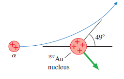
An alpha particle approaches a197Au nucleus with a speed of 1.50 × 10⁷m/s. As FIGURE CP37.47 shows, the alpha particle is scattered at a 49? angle at the slower speed of 1.49 × 10⁷m/s. In what direction does the197Au nucleus recoil, and with what speed? 49° 191 Au nucleus
Physicists first attempted to understand the hydrogen atom by applying the laws of classical physics. Consider an electron of mass m and charge -e in a circular orbit of radius r around a proton of charge +e.a. Use Newtonian physics to show that the total energy of the atom is E = -e2/8πє0r.b.
Consider an oil droplet of mass m and charge q. We want to determine the charge on the droplet in a Millikan-type experiment. We will do this in several steps. Assume, for simplicity, that the charge is positive and that the electric field between the plates points upward.a. An electric field is
A classical atom orbiting at frequency f would emit electromagnetic waves of frequency f because the electron’s orbit, seen edge-on, looks like an oscillating electric dipole.a. At what radius, in nm, would the electron orbiting the proton in a hydrogen atom emit light with a wavelength of 600
Firecracker A is 300 m from you. Firecracker B is 600 m from you in the same direction. You see both explode at the same time. Define event 1 to be “firecracker A explodes” and event 2 to be “firecracker B explodes.” Does event 1 occur before, after, or at the same time as event 2? Explain.
Bjorn is standing at x = 600 m. Firecracker 1 explodes at the origin and firecracker 2 explodes at x = 900 m. The flashes from both explosions reach Bjorn’s eye at t = 3.0 μs. At what time did each firecracker explode?
Jill claims that her new rocket is 100 m long. As she flies past your house, you measure the rocket’s length and find that it is only 80 m. What is Jill’s speed, as a fraction of c?
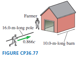
A very fast pole vaulter lives in the country. One day, while practicing, he notices a 10.0-m-long barn with the doors open at both ends. He decides to run through the barn at 0.866c while carrying his 16.0-m-long pole. The farmer, who sees him coming, says, ??Aha! This guy??s pole is length
A ball of mass m traveling at a speed of 0.80c has a perfectly inelastic collision with an identical ball at rest. If Newtonian physics were correct for these speeds, momentum conservation would tell us that a ball of mass 2m departs the collision with a speed of 0.40c. Let’s do a relativistic
Some particle accelerators allow protons (p+) and antiprotons (p-) to circulate at equal speeds in opposite directions in a device called a storage ring. The particle beams cross each other at various points to cause p+ + p- collisions. In one collision, the outcome is p+ + p- → e+ + e- + γ +
Two rockets are each 1000 m long in their rest frame. Rocket Orion, traveling at 0.80c relative to the earth, is overtaking rocket Sirius, which is poking along at a mere 0.60c. According to the crew on Sirius, how long does Orion take to completely pass? That is, how long is it from the instant
An electron moving to the right at 0.90c collides with a positron moving to the left at 0.90c. The two particles annihilate and produce two gamma-ray photons. What is the wavelength of the photons?
Consider the inelastic collision e- + e- → e- + e- + e- + e+ in which an electron-positron pair is produced in a head-on collision between two electrons moving in opposite directions at the same speed. This is similar to Figure 36.39, but both of the initial electrons are moving.a. What is
The nuclear reaction that powers the sun is the fusion of four protons into a helium nucleus. The process involves several steps, but the net reaction is simply 4p → 4He + energy. The mass of a proton, to four significant figures, is 1.673 × 10⁻²⁷ kg, and the mass of a helium nucleus is known to
The radioactive element radium (Ra) decays by a process known as alpha decay, in which the nucleus emits a helium nucleus. (These high-speed helium nuclei were named alpha particles when radioactivity was first discovered, long before the identity of the particles was established.) The reaction is
Showing 800 - 900
of 3693
First
2
3
4
5
6
7
8
9
10
11
12
13
14
15
16
Last
Step by Step Answers