New Semester
Started
Get
50% OFF
Study Help!
--h --m --s
Claim Now
Question Answers
Textbooks
Find textbooks, questions and answers
Oops, something went wrong!
Change your search query and then try again
S
Books
FREE
Study Help
Expert Questions
Accounting
General Management
Mathematics
Finance
Organizational Behaviour
Law
Physics
Operating System
Management Leadership
Sociology
Programming
Marketing
Database
Computer Network
Economics
Textbooks Solutions
Accounting
Managerial Accounting
Management Leadership
Cost Accounting
Statistics
Business Law
Corporate Finance
Finance
Economics
Auditing
Tutors
Online Tutors
Find a Tutor
Hire a Tutor
Become a Tutor
AI Tutor
AI Study Planner
NEW
Sell Books
Search
Search
Sign In
Register
study help
physics
physics scientists and engineers
Physics for Scientists and Engineers A Strategic Approach with Modern Physics 4th edition Randall D. Knight - Solutions
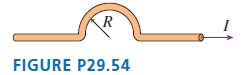
What is the magnetic field strength at the center of the semicircle in FIGURE P29.54? R FIGURE P29.54
The heart produces a weak magnetic field that can be used to diagnose certain heart problems. It is a dipole field produced by a current loop in the outer layers of the heart.a. It is estimated that the field at the center of the heart is 90 pT. What current must circulate around an 8.0-cm-diameter
The earth’s magnetic field, with a magnetic dipole moment of 8.0 × 10²² A m2, is generated by currents within the molten iron of the earth’s outer core. Suppose we model the core current as a 3000-km-diameter current loop made from a 1000-km-diameter “wire.” The loop diameter is measured
Weak magnetic fields can be measured at the surface of the brain.Although the currents causing these fields are quite complicated, we can estimate their size by modeling them as a current loop around the equator of a 16-cm-diameter (the width of a typical head) sphere.What current is needed to
The magnetic field strength at the north pole of a 2.0 cmdiameter, 8-cm-long Alnico magnet is 0.10 T. To produce the same field with a solenoid of the same size, carrying a current of 2.0 A, how many turns of wire would you need?
Your employer asks you to build a 20-cm-long solenoid with an interior field of 5.0 mT. The specifications call for a single layer of wire, wound with the coils as close together as possible. You have two spools of wire available. Wire with a #18 gauge has a diameter of 1.02 mm and has a maximum
A 2.5-m-long, 2.0-mm-diameter aluminum wire has a potential difference of 1.5 V between its ends. Consider an electron halfway between the center of the wire and the surface that is moving parallel to the wire at the drift speed. What is the ratio of the electric force on the electron to the
A scientist measuring the resistivity of a new metal alloy left her ammeter in another lab, but she does have a magnetic field probe. So she creates a 6.5-m-long, 2.0-mm diameter wire of the material, connects it to a 1.5 V battery, and measures a 3.0 mT magnetic field 1.0 mm from the surface of
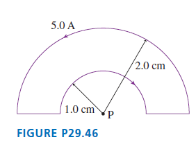
What are the strength and direction of the magnetic field at point P in FIGURE P29.46? 5.0 A 2.0 cm 1.0 cm FIGURE P29.46
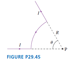
Find an expression for the magnetic field strength at the center (point P) of the circular arc in FIGURE P29.45. `R FIGURE P29.45
At what distance on the axis of a current loop is the magnetic field half the strength of the field at the center of the loop? Give your answer as a multiple of R.
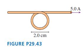
What are the strength and direction of the magnetic field at the center of the loop in FIGURE P29.43? 5.0 A 2.0 cm FIGURE P29.43
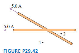
The two insulated wires in FIGURE P29.42 cross at a 30° angle but do not make electrical contact. Each wire carries a 5.0 A current. Points 1 and 2 are each 4.0 cm from the intersection and equally distant from both wires. What are the magnitude and direction of the magnetic fields at points 1
A long wire carrying a 5.0 A current perpendicular to the xy-plane intersects the x-axis at x = -2.0 cm. A second, parallel wire carrying a 3.0 A current intersects the x-axis at x = +2.0 cm. At what point or points on the x-axis is the magnetic field zero if(a) The two currents are in the same
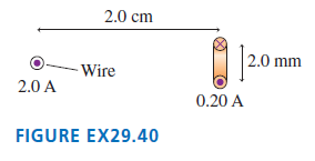
a. What is the magnitude of the torque on the current loop in FIGURE EX29.40?b. What is the loop€™s equilibrium orientation? 2.0 cm |2.0 mm - Wire 2.0 A 0.20 A FIGURE EX29.40
A small bar magnet experiences a 0.020 N m torque when the axis of the magnet is at 45° to a 0.10 T magnetic field. What is the magnitude of its magnetic dipole moment?
A square current loop 5.0 cm on each side carries a 500 mA current. The loop is in a 1.2 T uniform magnetic field. The axis of the loop, perpendicular to the plane of the loop, is 30° away from the field direction. What is the magnitude of the torque on the current loop?
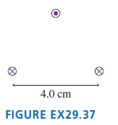
FIGURE EX29.37 is a cross section through three long wires with linear mass density 50 g/m. They each carry equal currents in the directions shown. The lower two wires are 4.0 cm apart and are attached to a table.What current I will allow the upper wire to €œfloat€ so as to
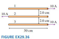
What is the net force (magnitude and direction) on each wire in FIGURE EX29.36? 10 A 2.0 cm 10 A 2.0 cm 10 A 50 cm FIGURE EX29.36 2.
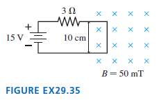
The right edge of the circuit in FIGURE EX29.35 extends into a 50 mT uniform magnetic field. What are the magnitude and direction of the net force on the circuit? ww 10 cm 15 V 1- х хXх B= 50 mT FIGURE EX29.35 х х
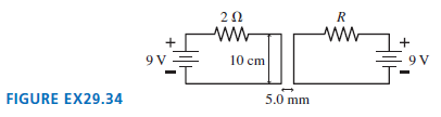
The two 10-cm-long parallel wires in FIGURE EX29.34 are separated by 5.0 mm. For what value of the resistor R will the force between the two wires be 5.4 × 10⁻⁵N? 10 cm FIGURE EX29.34 5.0 mm
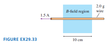
What magnetic field strength and direction will levitate the 2.0 g wire in FIGURE EX29.33? 2.0 g wire B-field region 1.5 A 10 cm FIGURE EX29.33
The Hall voltage across a conductor in a 55 mT magnetic field is 1.9 μV. When used with the same current in a different magnetic field, the voltage across the conductor is 2.8 μV. What is the strength of the second field?
The microwaves in a microwave oven are produced in a special tube called a magnetron. The electrons orbit the magnetic field at 2.4 GHz, and as they do so they emit 2.4 GHz electromagnetic waves.a. What is the magnetic field strength?b. If the maximum diameter of the electron orbit before the
To five significant figures, what are the cyclotron frequencies in a 3.0000 T magnetic field of the ions (a) O2+, (b) N2+, (c) CO+? The atomic masses are shown in the table; the mass of the missing electron is less than 0.001 u and is not relevant at this level of precision. Although N+2 and CO+
For your senior project, you would like to build a cyclotron that will accelerate protons to 10% of the speed of light. The largest vacuum chamber you can find is 50 cm in diameter. What magnetic field strength will you need?
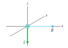
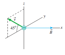
An electron moves in the magnetic field B = 0.50 î T with a speed of 1.0 × 10⁷m/s in the directions shown in FIGURE EX29.27.For each, what is magnetic force F on the electron? Give your answers in component form. a. b. y B
Radio astronomers detect electromagnetic radiation at 45 MHz from an interstellar gas cloud. They suspect this radiation is emitted by electrons spiraling in a magnetic field. What is the magnetic field strength inside the gas cloud?
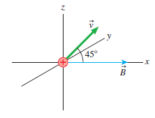
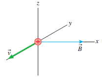
A proton moves in the magnetic field B = 0.50 î T with a speed of 1.0 × 10⁷m/s in the directions shown in FIGURE EX29.26. For each, what is magnetic force F on the proton? Give your answers in component form. a. b y 45° B
Magnetic resonance imaging needs a magnetic field strength of 1.5 T. The solenoid is 1.8 m long and 75 cm in diameter. It is tightly wound with a single layer of 2.0-mm-diameter superconducting wire. What size current is needed?
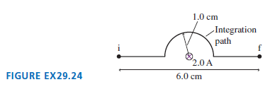
What is the line integral of B between points i and f in FIGURE EX29.24? 1.0 cm -Integration path 2.0 A 6.0 cm FIGURE EX29.24
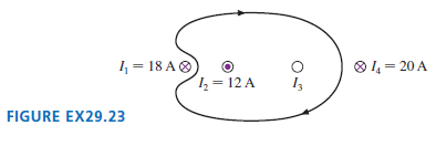
The value of the line integral of Bu around the closed path in FIGURE EX29.23 is 1.38 × 10⁻⁵T m. What are the direction (in or out of the page) and magnitude of I3? 1 = 18 AO O 1, = 20 A 1= 12 A 13 FIGURE EX29.23
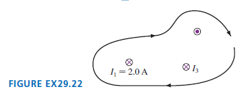
The value of the line integral of B around the closed path in FIGURE EX29.22 is 3.77 × 10⁻⁶T m. What is I3? O I3 1 = 2.0 A FIGURE EX29.22
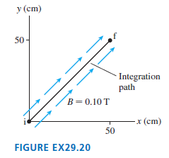
What is the line integral of B between points i and f in FIGURE EX29.20? у (cm) 50- Integration path В 3 0.10 T -x (cm) 50 FIGURE EX29.20
The earth’s magnetic dipole moment is 8.0 × 10²² A m2.a. What is the magnetic field strength on the surface of the earth at the earth’s north magnetic pole? How does this compare to the value in Table 29.1? You can assume that the current loop is deep inside the earth.b. Astronauts discover an
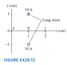
What are the magnetic fields at points a to c in FIGURE EX29.12? Give your answers as vectors. у (сm) 10 A 1 Long wires a b -x (cm) 2 -1 10 A FIGURE EX29.12
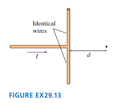
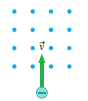
A wire carries current I into the junction shown in FIGURE EX29.13. What is the magnetic field at the dot? Identical wires d FIGURE EX29.13
The on-axis magnetic field strength 10 cm from a small bar magnet is 5.0 μT.a. What is the bar magnet’s magnetic dipole moment?b. What is the on-axis field strength 15 cm from the magnet?
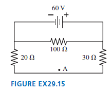
Point A in FIGURE EX29.15 is 2.0 mm from the wire. What is the magnetic field strength at point A? You can assume that the wire is very long and that all other wires are too far away to contribute to the magnetic field. 60 V + 100 N 20 Ω 30 Ω • A FIGURE EX29.15 ww ww
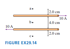
What are the magnetic field strength and direction at points a to c in FIGURE EX29.14? a. ]2.0 cm 10 A b. 4.0 cm 10 A [2.0 cm c. FIGURE EX29.14
Give a step-by-step explanation, using both words and pictures, of how a permanent magnet can pick up a piece of non-magnetized iron.
The magnetic field at the center of a 1.0-cm-diameter loop is 2.5 mT.a. What is the current in the loop?b. A long straight wire carries the same current you found in part a. At what distance from the wire is the magnetic field 2.5 mT?
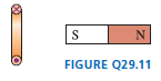
The south pole of a bar magnet is brought toward the current loop of FIGURE Q29.11. Does the bar magnet attract, repel, or have no effect on the loop? Explain. FIGURE Q29.11 %24
A biophysics experiment uses a very sensitive magnetic field probe to determine the current associated with a nerve impulse traveling along an axon. If the peak field strength 1.0 mm from an axon is 8.0 pT, what is the peak current carried by the axon?
You have a horizontal cathode-ray tube (CRT) for which the controls have been adjusted such that the electron beam should make a single spot of light exactly in the center of the screen. You observe, however, that the spot is deflected to the right. It is possible that the CRT is broken. But as a
Determine the magnetic field direction that causes the charged particles shown in FIGURE Q29.9 to experience the indicated magnetic force. a. b. Fout of page
The element niobium, which is a metal, is a superconductor (i.e., no electrical resistance) at temperatures below 9 K. However, the superconductivity is destroyed if the magnetic field at the surface of the metal reaches or exceeds 0.10 T. What is the maximum current in a straight, 3.0-mm diameter
What currents are needed to generate the magnetic field strengths of Table 29.1 at a point 1.0 cm from a long, straight wire?Table 29.1Field source......................Field strength (T)Surface of the earth ..........5 × 10-5Refrigerator magnet .........5 × 10-3Laboratory magnet ............0.1
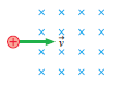
What is the initial direction of deflection for the charged particles entering the magnetic fields shown in FIGURE Q29.6? a. b. x x x x x x x x x x x x
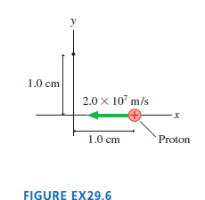
What is the magnetic field at the position of the dot in FIGURE EX29.6? Give your answer as a vector. y 1.0 cm 2.0 x 10" m/s 1.0 cm Proton FIGURE EX29.6
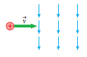
What is the initial direction of deflection for the charged particles entering the magnetic fields shown in FIGURE Q29.7? a. b.
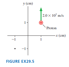
What is the magnetic field at the position of the dot in FIGURE EX29.5? Give your answer as a vector. y (cm) 2.0 x 10' m/s 1 +) Proton -x (cm) -1 1 -1- FIGURE EX29.5
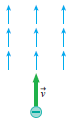
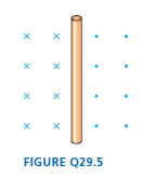
What is the current direction in the wire of FIGURE Q29.5? Explain. FIGURE Q29.5 x x x x
An electron moves along the z-axis with vz = 2.0 × 10⁷ m/s. As it passes the origin, what are the strength and direction of the magnetic field at the (x, y, z) positions(a) (1 cm, 0 cm, 0 cm),(b) (0 cm, 0 cm, 1 cm),(c) (0 cm, 1 cm, 1 cm)?
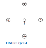
What is the current direction in the wire of FIGURE Q29.4? Explain. FIGURE Q29.4
A proton moves along the x-axis with vx = 1.0 × 10⁷ m/s. As it passes the origin, what are the strength and direction of the magnetic field at the (x, y, z) positions(a) (1 cm, 0 cm, 0 cm),(b) (0 cm, 1 cm, 0 cm),(c) (0 cm, -2 cm, 0 cm)?
You have two electrically neutral metal cylinders that exert strong attractive forces on each other. You have no other metal objects. Can you determine if both of the cylinders are magnets, or if one is a magnet and the other is just a piece of iron? If so, how? If not, why not?
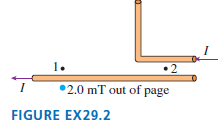
Points 1 and 2 in FIGURE EX29.2 are the same distance from the wires as the point where B = 2.0 mT. What are the strength and direction of B at points 1 and 2? 1. I 2.0 mT out of page FIGURE EX29.2
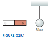
The lightweight glass sphere in FIGURE Q29.1 hangs by a thread. The north pole of a bar magnet is brought near the sphere. a. Suppose the sphere is electrically neutral. Is it attracted to, repelled by, or not affected by the magnet? Explain.b. Answer the same question if the sphere is positively
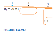
What is the magnetic field strength at points 2 to 4 in FIGURE EX29.1? Assume that the wires overlap closely at 2 and 3, that each point is the same distance from nearby wires, and that all other wires are too far away to contribute to the field. 2 3 B, = 20 mT 4 FIGURE EX29.1
You’ve decided to protect your house by placing a 5.0-m-tall iron lightning rod next to the house. The top is sharpened to a point and the bottom is in good contact with the ground. From your research, you’ve learned that lightning bolts can carry up to 50 kA of current and last up to 50 μs.a.
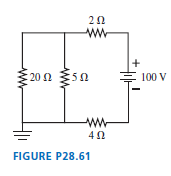
What is the current through the 20 Ω resistor in FIGURE P28.61? 20 : 20 Ω 5Ω 100 V FIGURE P28.61
The electron drift speed in a 1.0-mm-diameter gold wire is 5.0 × 10⁻⁵ m/s. How long does it take 1 mole of electrons to flow through a cross section of the wire?
The total amount of charge in coulombs that has entered a wire at time t is given by the expression Q = 4t - t2, where t is in seconds and t ≥ 0.a. Find an expression for the current in the wire at time t.b. Graph I versus t for the interval 0 ≤ t ≤ 4 s.
Electrons flow through a 1.6-mm-diameter aluminum wire at 2.0 × 10⁻⁴ m/s. How many electrons move through a cross section of the wire each day?
a. How many conduction electrons are there in a 1.0-mm diameter gold wire that is 10 cm long?b. How far must the sea of electrons in the wire move to deliver -32 nC of charge to an electrode?
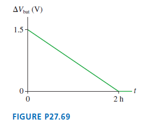
A 1.5 V flashlight battery is connected to a wire with a resistance of 3.0 Ω. Figure P27.69 shows the battery€™s potential difference as a function of time. What is the total charge lifted by the charge escalator? AV bat (V) 1.5 0- 2h FIGURE P27.69
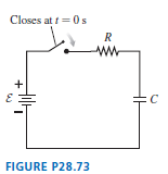
The capacitor in FIGURE P28.73 begins to charge after the switch closes at t = 0 s. a. What is ΔVC a very long time after the switch has closed?b. What is Qmax in terms of Ԑ, R, and C?c. In this circuit, does I = +dQ/dt or -dQ/dt? Explain.d. Find an expression for the current I at time t. Graph
A circuit you’re using discharges a 20 μF capacitor through an unknown resistor. After charging the capacitor, you close a switch at t = 0 s and then monitor the resistor current with an ammeter. Your data are as follows:Time (s)...................Current (μA)0.5
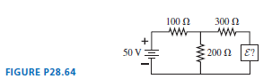
For what emf E does the 200 Ω resistor in FIGURE P28.64 dissipate no power? Should the emf be oriented with its positive terminal at the top or at the bottom? 100 0 300 N 50 V :200 N E? FIGURE P28.64
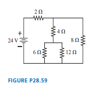
For the circuit shown in FIGURE P28.59, find the current through and the potential difference across each resistor. Place your results in a table for ease of reading. 20 24 VE 80 120 12Ω FIGURE P28.59
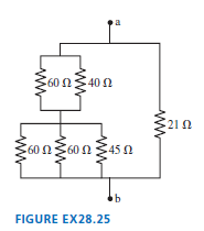
What is the equivalent resistance between points a and b in FIGURE EX28.25? a 60 Ω40 Ω 210 60 N60 N 45 Ω b FIGURE EX28.25
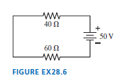
What is the magnitude of the potential difference across each resistor in FIGURE EX28.6? 40 N 50 V 60 N ww FIGURE EX28.6
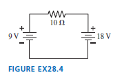
a. What are the magnitude and direction of the current in the 10 Ω resistor in FIGURE EX28.4? b. Draw a graph of the potential as a function of the distance traveled through the circuit, traveling cw from V = 0 V at the lower left corner. ww 10 0 9 V 18 V FIGURE EX28.4
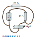
Draw a circuit diagram for the circuit of FIGURE EX28.2. 100 0 50n 12 V 10 uF FIGURE EX28.2
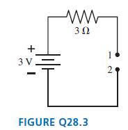
The wire is broken on the right side of the circuit in FIGURE Q28.3. What is the potential difference V1- V2between points 1 and 2? Explain. 1 3 V. 2 FIGURE Q28.3
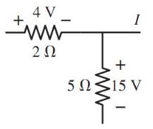
In FIGURE EX28.3, what is the magnitude of the current in the wire to the right of the junction? Does the charge in this wire flow to the right or to the left? 4 V - 1 20 50Š15 V FIGURE EX28.3
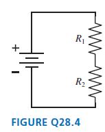
The circuit of FIGURE Q28.4 has two resistors, with R1> R2. Which of the two resistors dissipates the larger amount of power? Explain. R R2 FIGURE Q28.4
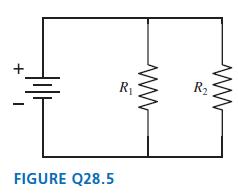
The circuit of FIGURE Q28.5 has two resistors, with R1> R2. Which of the two resistors dissipates the larger amount of power? Explain. R2 R1 FIGURE Q28.5 ww-
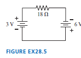
a. What are the magnitude and direction of the current in the 18 Ω resistor in FIGURE EX28.5? b. Draw a graph of the potential as a function of the distance traveled through the circuit, traveling cw from V = 0 V at the lower left corner. 18 0 3 V 6 + FIGURE EX28.5
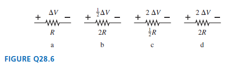
Rank in order, from largest to smallest, the powers Pato Pddissipated by the four resistors in FIGURE Q28.6. 2 Δν 2 Δν Δν ww ww 2R 2R a FIGURE Q28.6
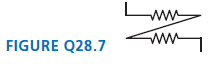
Are the two resistors in FIGURE Q28.7 in series or in parallel? Explain. ww FIGURE Q28.7
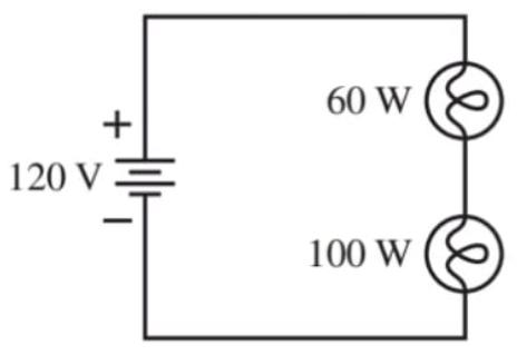
A 60 W light-bulb and a 100 W lightbulb are placed in the circuit shown in FIGURE EX28.9. Both bulbs are glowing.a. Which bulb is brighter? Or are they equally bright?b. Calculate the power dissipated by each bulb. 60 W 120 VE 100 W FIGURE EX28.9
What is the resistance of a 1500 W (120 V) hair dryer? What is the current in the hair dryer when it is used?
A battery with internal resistance r is connected to a load resistance R. If R is increased, does the terminal voltage of the battery increase, decrease, or stay the same? Explain.
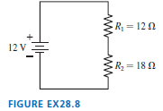
How much power is dissipated by each resistor in FIGURE EX28.8? R = 12 N 12 V R = 18 0 FIGURE EX28.8 ww
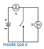
Initially bulbs A and B in FIGURE Q28.9 are glowing. What happens to each bulb if the switch is closed? Does it get brighter, stay the same, get dimmer, or go out? Explain. A B FIGURE Q28.9
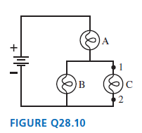
Bulbs A, B, and C in FIGURE Q28.10 are identical, and all are glowing. a. Rank in order, from most to least, the brightnesses of the three bulbs. Explain.b. Suppose a wire is connected between points 1 and 2. What happens to each bulb? Does it get brighter, stay the same, get dimmer, or go out?
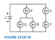
The five identical bulbs in FIGURE EX28.10 are all glowing.The battery is ideal. What is the order of brightness of the bulbs, from brightest to dimmest? Some may be equal. A. P = S > Q = R = TB. P = S = T > Q = RC. P > S = T > Q = RD. P > Q = R > S = T P R T FIGURE EX28.10
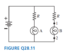
Bulbs A and B in FIGURE Q28.11 are identical, and both are glowing. Bulb B is removed from its socket. Does the potential difference ΔV12between points 1 and 2 increase, stay the same, decrease, or become zero? Explain. ER A B FIGURE Q28.11
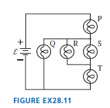
The five identical bulbs in FIGURE EX28.11 are all glowing.The battery is ideal. What is the order of brightness of the bulbs, from brightest to dimmest? Some may be equal. A. P = T > Q = R = SB. P > Q = R = S > TC. P = T > Q > R = SD. P > Q > T > R = S R S T FIGURE EX28.11
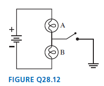
Bulbs A and B in FIGURE Q28.12 are identical, and both are glowing. What happens to each bulb when the switch is closed?Does its brightness increase, stay the same, decrease, or go out? Explain. FIGURE Q28.12
1 kWh is how many joules?
A typical American family uses 1000 kWh of electricity a month.a. What is the average current in the 120 V power line to the house?b. On average, what is the resistance of a household?
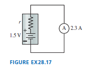
The battery in FIGURE EX28.17 is short-circuited by an ideal ammeter having zero resistance. a. What is the battery??s internal resistance?b. How much power is dissipated inside the battery? A) 2.3 A 1.5 V FIGURE EX28.17
A waterbed heater uses 450 W of power. It is on 25% of the time, off 75%. What is the annual cost of electricity at a billing rate of $0.12/kWh?
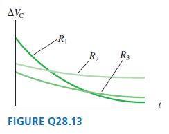
FIGURE Q28.13 shows the voltage as a function of time of a capacitor as it is discharged (separately) through three different resistors.Rank in order, from largest to smallest, the values of the resistances R1to R3. AVe R1 R3 R2 FIGURE Q28.13
A standard 100 W (120 V) lightbulb contains a 7.0-cm-long tungsten filament. The high-temperature resistivity of tungsten is 9.0 × 10⁻⁷ Ω m. What is the diameter of the filament?
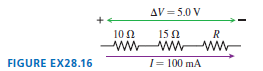
What is the value of resistor R in FIGURE EX28.16? AV = 5.0 V 10 0 150 R ww www- FIGURE EX28.16 I= 100 mA
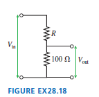
The circuit in FIGURE EX28.18 is called a voltage divider.What value of R will make Vout= Vin/10? ER Va 100 n V FIGURE EX28.18
Showing 1500 - 1600
of 3693
First
9
10
11
12
13
14
15
16
17
18
19
20
21
22
23
Last
Step by Step Answers