New Semester
Started
Get
50% OFF
Study Help!
--h --m --s
Claim Now
Question Answers
Textbooks
Find textbooks, questions and answers
Oops, something went wrong!
Change your search query and then try again
S
Books
FREE
Study Help
Expert Questions
Accounting
General Management
Mathematics
Finance
Organizational Behaviour
Law
Physics
Operating System
Management Leadership
Sociology
Programming
Marketing
Database
Computer Network
Economics
Textbooks Solutions
Accounting
Managerial Accounting
Management Leadership
Cost Accounting
Statistics
Business Law
Corporate Finance
Finance
Economics
Auditing
Tutors
Online Tutors
Find a Tutor
Hire a Tutor
Become a Tutor
AI Tutor
AI Study Planner
NEW
Sell Books
Search
Search
Sign In
Register
study help
physics
physics scientists and engineers
Physics for Scientists and Engineers A Strategic Approach with Modern Physics 4th edition Randall D. Knight - Solutions
The magnetic field at one place on the earth’s surface is 55 μT in strength and tilted 60° down from horizontal. A 200-turn coil having a diameter of 4.0 cm and a resistance of 2.0 Ω is connected to a 1.0 μF capacitor rather than to a current meter. The coil is held in a horizontal plane and
A 10-turn coil of wire having a diameter of 1.0 cm and a resistance of 0.20 Ω is in a 1.0 mT magnetic field, with the coil oriented for maximum flux. The coil is connected to an uncharged 1.0 μF capacitor rather than to a current meter. The coil is quickly pulled out of the magnetic field.
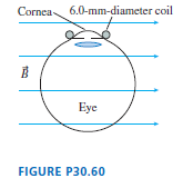
Experiments to study vision often need to track the movements of a subject??s eye. One way of doing so is to have the subject sit in a magnetic field while wearing special contact lenses with a coil of very fine wire circling the edge. A current is induced in the coil each time the subject rotates
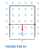
FIGURE P30.59 shows a U-shaped conducting rail that is oriented vertically in a horizontal magnetic field. The rail has no electric resistance and does not move. A slide wire with mass m and resistance R can slide up and down without friction while maintaining electrical contact with the rail. The
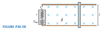
You??ve decided to make the magnetic projectile launcher shown in FIGURE P30.58 for your science project. An aluminum bar of length l slides along metal rails through a magnetic field B. The switch closes at t = 0 s, while the bar is at rest, and a battery of emf Ԑbatstarts a current flowing
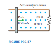
The 10-cm-wide, zero-resistance slide wire shown in FIGURE P30.57 is pushed toward the 2.0 Ω resistor at a steady speed of 0.50 m/s. The magnetic field strength is 0.50 T. a. How big is the pushing force?b. How much power does the pushing force supply to the wire?c. What are the direction and
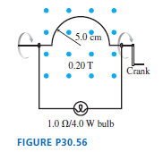
Your camping buddy has an idea for a light to go inside your tent. He happens to have a powerful (and heavy!) horseshoe magnet that he bought at a surplus store. This magnet creates a 0.20 T field between two pole tips 10 cm apart. His idea is to build the hand-cranked generator shown in FIGURE
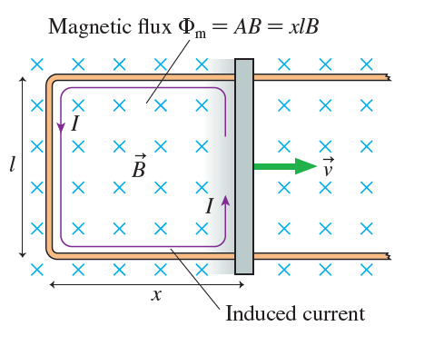
A 20-cm-long, zero-resistance slide wire moves outward, on zero-resistance rails, at a steady speed of 10 m/s in a 0.10 T magnetic field. (See Figure 30.26.) On the opposite side, a 1.0 Ω carbon resistor completes the circuit by connecting the two rails.The mass of the resistor is 50
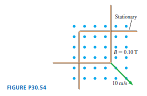
The L-shaped conductor in FIGURE P30.54 moves at 10 m/s across and touches a stationary L-shaped conductor in a 0.10 T magnetic field. The two vertices overlap, so that the enclosed area is zero, at t = 0 s. The conductor has a resistance of 0.010 ohms per meter. a. What is the direction of the
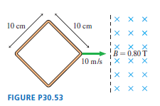
The square loop shown in FIGURE P30.53 moves into a 0.80 T magnetic field at a constant speed of 10 m/s. The loop has a resistance of 0.10 Ω, and it enters the field at t = 0 s. a. Find the induced current in the loop as a function of time. Give your answer as a graph of I versus t from t = 0 s to
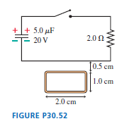
A rectangular metal loop with 0.050 Ω resistance is placed next to one wire of the RC circuit shown in FIGURE P30.52. The capacitor is charged to 20 V with the polarity shown, then the switch is closed at t = 0 s. a. What is the direction of current in the loop for t > 0 s?b. What is the
A small, 2.0-mm-diameter circular loop with R = 0.020 Ω is at the center of a large 100-mm-diameter circular loop. Both loops lie in the same plane. The current in the outer loop changes from +1.0 A to -1.0 A in 0.10 s. What is the induced current in the inner loop?
A 40-turn, 4.0-cm-diameter coil with R = 0.40 Ω surrounds a 3.0-cm-diameter solenoid. The solenoid is 20 cm long and has 200 turns. The 60 Hz current through the solenoid is I = I0 sin(2πft). What is I0 if the maximum induced current in the coil is 0.20 A?
An electric generator has an 18-cm-diameter, 120-turn coil that rotates at 60 Hz in a uniform magnetic field that is perpendicular to the rotation axis. What magnetic field strength is needed to generate a peak voltage of 170 V?
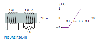
FIGURE P30.48 shows two 20-turn coils tightly wrapped on the same 2.0-cm-diameter cylinder with 1.0-mm-diameter wire. The current through coil 1 is shown in the graph. Determine the current in coil 2 at (a) T = 0.05 s (b) T = 0.25 s. A positive current is into the page at the top of a loop. Assume
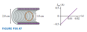
FIGURE P30.47 shows a 1.0-cm-diameter loop with R = 0.50 Ω inside a 2.0-cm-diameter solenoid. The solenoid is 8.0 cm long, has 120 turns, and carries the current shown in the graph. A positive current is cw when seen from the left. Determine the current in the loop at t = 0.010 s. I (A) 0.54 1.0
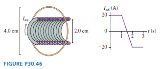
FIGURE P30.46 shows a 4.0-cm-diameter loop with resistance 0.10 Ω around a 2.0-cm-diameter solenoid. The solenoid is 10 cm long, has 100 turns, and carries the current shown in the graph. A positive current is cw when seen from the left. Find the current in the loop at (a) T = 0.5 s, (b) T = 1.5
A 2.0 cm × 2.0 cm square loop of wire with resistance 0.010 Ω has one edge parallel to a long straight wire. The near edge of the loop is 1.0 cm from the wire. The current in the wire is increasing at the rate of 100 A/s. What is the current in the loop?
A 20 cm × 20 cm square loop of wire lies in the xy-plane with its bottom edge on the x-axis. The resistance of the loop is 0.50 Ω. A magnetic field parallel to the z-axis is given by B = 0.80y2t, where B is in tesla, y in meters, and t in seconds.What is the size of the induced current in the
A 3.0-cm-diameter, 10-turn coil of wire, located at z = 0 in the xy-plane, carries a current of 2.5 A. A 2.0-mm-diameter conducting loop with 2.0 × 10⁻⁴ Ω resistance is also in the xy-plane at the center of the coil. At t = 0 s, the loop begins to move along the z-axis with a constant speed of 75
A spherical balloon with a volume of 2.5 L is in a 45 mT uniform, vertical magnetic field. A horizontal elastic but conducting wire with 2.5 Ω resistance circles the balloon at its equator. Suddenly the balloon starts expanding at 0.75 L/s .What is the current in the wire 2.0 s later?
A circular loop made from a flexible, conducting wire is shrinking. Its radius as a function of time is r = r0e-βt. The loop is perpendicular to a steady, uniform magnetic field B. Find an expression for the induced emf in the loop at time t.
A 100-turn, 8.0-cm-diameter coil is made of 0.50-mm diameter copper wire. A magnetic field is parallel to the axis of the coil. At what rate must B increase to induce a 2.0 A current in the coil?
A 100-turn, 2.0-cm-diameter coil is at rest with its axis vertical. A uniform magnetic field 60° away from vertical increases from 0.50 T to 1.50 T in 0.60 s. What is the induced emf in the coil?
A 20 cm × 20 cm square loop has a resistance of 0.10 Ω. A magnetic field perpendicular to the loop is B = 4t - 2t2, where B is in tesla and t is in seconds. What is the current in the loop at t = 0.0 s, t = 1.0 s, and t = 2.0 s?
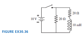
The switch in FIGURE EX30.36 has been open for a long time. It is closed at t = 0 s. a. What is the current through the battery immediately after the switch is closed?b. What is the current through the battery after the switch has been closed a long time? 20 N 10 V 20 Ω 10 mH FIGURE EX30.36 ww
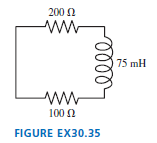
At t = 0 s, the current in the circuit in FIGURE EX30.35 is I0. At what time is the current 1/2 I0? 200 1 ww 75 mH ww- 100 N FIGURE EX30.35 lell
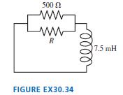
What value of resistor R gives the circuit in FIGURE EX30.34 a time constant of 25 μs? 500 N ww ww R 17.5 mH FIGURE EX30.34
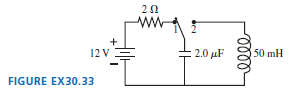
The switch in FIGURE EX30.33 has been in position 1 for a long time. It is changed to position 2 at t = 0 s. a. What is the maximum current through the inductor?b. What is the first time at which the current is maximum? 20 + 12 V 2.0 μF 50 mH FIGURE EX30.33
An LC circuit has a 10 mH inductor. The current has its maximum value of 0.60 A at t = 0 s. A short time later the capacitor reaches its maximum potential difference of 60 V. What is the value of the capacitance?
An MRI machine needs to detect signals that oscillate at very high frequencies. It does so with an LC circuit containing a 15 mH coil. To what value should the capacitance be set to detect a 450 MHz signal?
A 2.0 mH inductor is connected in parallel with a variable capacitor. The capacitor can be varied from 100 pF to 200 pF. What is the range of oscillation frequencies for this circuit?
An FM radio station broadcasts at a frequency of 100 MHz. What inductance should be paired with a 10 pF capacitor to build a receiver circuit for this station?
MRI (magnetic resonance imaging) is a medical technique that produces detailed “pictures” of the interior of the body. The patient is placed into a solenoid that is 40 cm in diameter and 1.0 m long. A 100 A current creates a 5.0 T magnetic field inside the solenoid. To carry such a large
How much energy is stored in a 3.0-cm-diameter, 12-cm long solenoid that has 200 turns of wire and carries a current of 0.80 A?
A 100 mH inductor whose windings have a resistance of 4.0 Ω is connected across a 12 V battery having an internal resistance of 2.0 Ω. How much energy is stored in the inductor?
What is the potential difference across a 10 mH inductor if the current through the inductor drops from 150 mA to 50 mA in 10 μs?What is the direction of this potential difference? That is, does the potential increase or decrease along the direction of the current?
The maximum allowable potential difference across a 200 mH inductor is 400 V. You need to raise the current through the inductor from 1.0 A to 3.0 A. What is the minimum time you should allow for changing the current?
The charger for your electronic devices is a transformer.Suppose a 60 Hz outlet voltage of 120 V needs to be reduced to a device voltage of 3.0 V. The side of the transformer attached to the electronic device has 60 turns of wire. How many turns are on the side that plugs into the outlet?
Electricity is distributed from electrical substations to neighborhoods at 15,000 V. This is a 60 Hz oscillating (AC) voltage. Neighborhood transformers, seen on utility poles, step this voltage down to the 120 V that is delivered to your house.a. How many turns does the primary coil on the
Scientists studying an anomalous magnetic field find that it is inducing a circular electric field in a plane perpendicular to the magnetic field. The electric field strength 1.5 m from the center of the circle is 4.0 mV/m. At what rate is the magnetic field changing?
The magnetic field inside a 5.0-cm-diameter solenoid is 2.0 T and decreasing at 4.0 T/s. What is the electric field strength inside the solenoid at a point(a) On the axis(b) 2.0 cm from the axis?
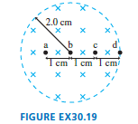
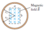
The magnetic field in FIGURE EX30.19 is decreasing at the rate 0.10 T/s. What is the acceleration (magnitude and direction) of a proton initially at rest at points a to d? 2.0 сm b d a Tem"1 cm"I cm FIGURE EX30.19
A 1000-turn coil of wire 1.0 cm in diameter is in a magnetic field that increases from 0.10 T to 0.30 T in 10 ms. The axis of the coil is parallel to the field. What is the emf of the coil?
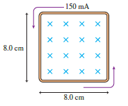
The resistance of the loop in FIGURE EX30.15 is 0.20 Ω. Is the magnetic field strength increasing or decreasing? At what rate (T/s)? 150 mA x x x X x x X 8.0 сm x x X x x x X 8.0 сm
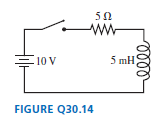
For the circuit of FIGURE Q30.14: a. What is the battery current immediately after the switch closes? Explain.b. What is the battery current after the switch has been closed a long time? Explain. 50 ww E10 V 5 mH FIGURE Q30.14
FIGURE EX30.14 shows a 10-cm-diameter loop in three different magnetic fields. The loop??s resistance is 0.20 Ω. For each, what are the size and direction of the induced current? a. b. c. X X
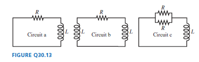
Rank in order, from largest to smallest, the three time constants τato τcfor the three circuits in FIGURE Q30.13. Explain. R R R ww ww R Circuit a L Circuit b L Circuit c L FIGURE Q30.13 ele ell
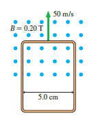
The loop in FIGURE EX30.13 is being pushed into the 0.20 T magnetic field at 50 m/s. The resistance of the loop is 0.10 Ω. What are the direction and the magnitude of the current in the loop? 50 m/s B= 0.20 T 5.0 сm
An LC circuit oscillates at a frequency of 2000 Hz. What will the frequency be if the inductance is quadrupled?
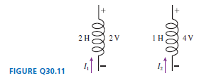
a. Can you tell which of the inductors in FIGURE Q30.11 has the larger current through it? If so, which one? Explain.b. Can you tell through which inductor the current is changing more rapidly? If so, which one? Explain.c. If the current enters the inductor from the bottom, can you tell if the
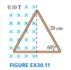
The metal equilateral triangle in FIGURE EX30.11, 20 cm on each side, is halfway into a 0.10 T magnetic field. a. What is the magnetic flux through the triangle?b. If the magnetic field strength decreases, what is the direction of the induced current in the triangle? 0.10 T X XI XX X Xx x/xi 120
An inductor with a 2.0 A current stores energy. At what current will the stored energy be twice as large?
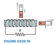
A solenoid is wound as shown in FIGURE EX30.10. a. Is there an induced current as magnet 1 is moved away from the solenoid? If so, what is the current direction through resistor R?b. Is there an induced current as magnet 2 is moved away from the solenoid? If so, what is the current direction
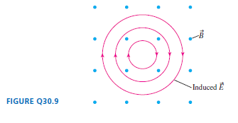
Is the magnetic field strength in FIGURE Q30.9 increasing, decreasing, or steady? Explain. Induced E FIGURE Q30.9
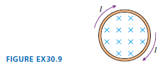
There is a cw induced current in the conducting loop shown in FIGURE EX30.9. Is the magnetic field inside the loop increasing in strength, decreasing in strength, or steady? X X x x x x X X X X FIGURE EX30.9
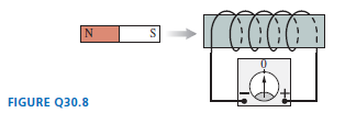
FIGURE Q30.8 shows a bar magnet, a coil of wire, and a current meter. Is the current through the meter right to left, left to right, or zero for the following circumstances? Explain. a. The magnet is inserted into the coil.b. The magnet is held at rest inside the coil.c. The magnet is withdrawn
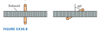
FIGURE EX30.8 shows a 2.0-cm-diameter solenoid passing through the center of a 6.0-cm-diameter loop. The magnetic field inside the solenoid is 0.20 T. What is the magnetic flux through the loop when it is perpendicular to the solenoid and when it is tilted at a 60? angle? Solenoid 60 FIGURE EX30.8
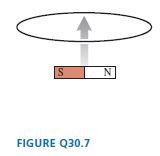
A bar magnet is pushed toward a loop of wire as shown in FIGURE Q30.7. Is there a current in the loop? If so, in which direction? If not, why not? N FIGURE Q30.7
What is the magnetic flux through the loop shown in FIGURE EX30.7? Magnetic field B XXXXX
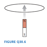
FIGURE Q30.6 shows a bar magnet being pushed toward a conducting loop from below, along the axis of the loop. a. What is the current direction in the loop? Explain.b. Is there a magnetic force on the loop? If so, in which direction? Explain.c. Is there a force on the magnet? If so, in which
An equilateral triangle 8.0 cm on a side is in a 5.0 mT uniform magnetic field. The magnetic flux through the triangle is 6.0 μWb. What is the angle between the magnetic field and an axis perpendicular to the plane of the triangle?
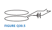
The two loops of wire in FIGURE Q30.5 are stacked one above the other. Does the upper loop have a clockwise current, a counterclockwise current, or no current at the following times? Explain. a. Before the switch is closed.b. Immediately after the switch is closed.c. Long after the switch is
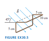
FIGURE EX30.5 shows a 10 cm × 10 cm square bent at a 90? angle. A uniform 0.050 T magnetic field points downward at a 45? angle. What is the magnetic flux through the loop? 5 сm 10 ст 45 5 сm FIGURE EX30.5
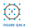
Does the loop of wire in FIGURE Q30.4 have a clockwise current, a counterclockwise current, or no current under the following circumstances? Explain. a. The magnetic field points out of the page and is increasing.b. The magnetic field points out of the page and is constant.c. The magnetic field
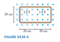
What is the magnetic flux through the loop shown in FIGURE EX30.4? x x x x . X_X xx. Xx . 1.0T 2.0T 20 cm xx"X x. XX x X Xx X X .. 20 сm 20 сm FIGURE EX30.4
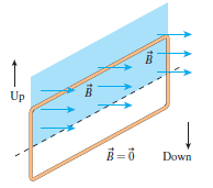
A vertical, rectangular loop of copper wire is half in and half out of the horizontal magnetic field in FIGURE Q30.3. (The field is zero beneath the dashed line.) The loop is released and starts to fall. Is there a net magnetic force on the loop? If so, in which direction? Explain. Up Down
A 10-cm-long wire is pulled along a U-shaped conducting rail in a perpendicular magnetic field. The total resistance of the wire and rail is 0.20 Ω. Pulling the wire at a steady speed of 4.0 m/s causes 4.0 W of power to be dissipated in the circuit.a. How big is the pulling force?b. What is the
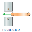
You want to insert a loop of copper wire between the two permanent magnets in FIGURE Q30.2. Is there an attractive magnetic force that tends to pull the loop in, like a magnet pulls on a paper clip? Or do you need to push the loop in against a repulsive force? Explain. N FIGURE Q30.2
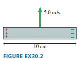
A potential difference of 0.050 V is developed across the 10-cm-long wire of FIGURE EX30.2 as it moves through a magnetic field perpendicular to the page. What are the strength and direction (in or out) of the magnetic field? 5.0 m/s 10 cm FIGURE EX30.2 +++
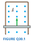
What is the direction of the induced current in FIGURE Q30.1? FIGURE Q30.1
The earth’s magnetic field strength is 5.0 × 10⁻⁵ T. How fast would you have to drive your car to create a 1.0 V motional emf along your 1.0-m-tall radio antenna? Assume that the motion of the antenna is perpendicular to B.
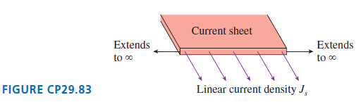
An infinitely wide flat sheet of charge flows out of the page in FIGURE CP29.83. The current per unit width along the sheet (amps per meter) is given by the linear current density Js.a. What is the shape of the magnetic field? To answer this question, you may find it helpful to approximate the
A long, straight conducting wire of radius R has a nonuniform current density J = J0r/R, where J0 is a constant. The wire carries total current I.a. Find an expression for J0 in terms of I and R.b. Find an expression for the magnetic field strength inside the wire at radius r.c. At the boundary, r
A flat, circular disk of radius R is uniformly charged with total charge Q. The disk spins at angular velocity ω about an axis through its center. What is the magnetic field strength at the center of the disk?
a. Derive an expression for the magnetic field strength at distance d from the center of a straight wire of finite length l that carries current I.b. Determine the field strength at the center of a current carrying square loop having sides of length 2R.c. Compare your answer to part b to the field
You have a 1.0-m-long copper wire. You want to make an N turn current loop that generates a 1.0 mT magnetic field at the center when the current is 1.0 A. You must use the entire wire.What will be the diameter of your coil?
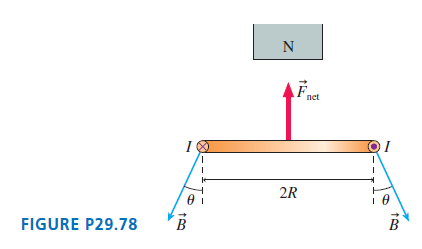
A nonuniform magnetic field exerts a net force on a current loop of radius R. FIGURE P29.78 shows a magnetic field that is diverging from the end of a bar magnet. The magnetic field at the position of the current loop makes an angle θ with respect to the vertical.a. Find an expression
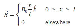
A wire along the x-axis carries current I in the negative x direction through the magnetic field a. Draw a graph of B versus x over the interval -3/2 l < x < 3/2 l.b. Find an expression for the net force Fnet on the wire.c. Find an expression for the net torque on the wire about the point x
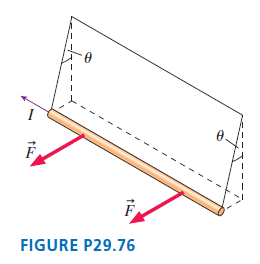
a. In FIGURE P29.76, a long, straight, current-carrying wire of linear mass density μ is suspended by threads. A magnetic field perpendicular to the wire exerts a horizontal force that deflects the wire to an equilibrium angle θ. Find an expression for the strength and
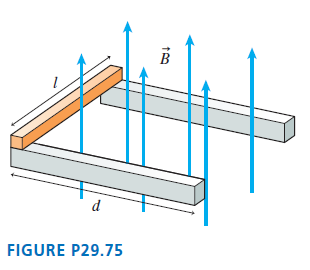
A conducting bar of length l and mass m rests at the left end of the two frictionless rails of length d in FIGURE P29.75. A uniform magnetic field of strength B points upward.a. In which direction, into or out of the page, will a current through the conducting bar cause the bar to experience a
Magnetic fields are sometimes measured by balancing magnetic forces against known mechanical forces. Your task is to measure the strength of a horizontal magnetic field using a 12-cm-long rigid metal rod that hangs from two nonmagnetic springs, one at each end, with spring constants 1.3 N/m. You
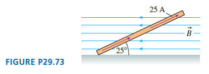
FIGURE P29.73 is an edge view of a 2.0 kg square loop, 2.5 m on each side, with its lower edge resting on a frictionless, horizontal surface. A 25 A current is flowing around the loop in the direction shown. What is the strength of a uniform, horizontal magnetic field for which the loop is in
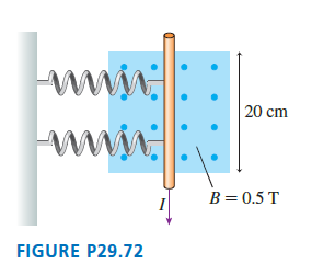
The two springs in FIGURE P29.72 each have a spring constant of 10 N/m. They are compressed by 1.0 cm when a current passes through the wire. How big is the current? www 20 cm www. B=0.5 T FIGURE P29.72
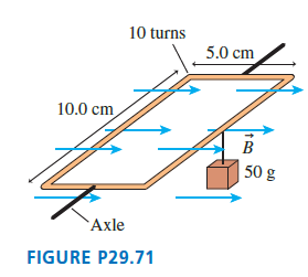
The 10-turn loop of wire shown in FIGURE P29.71 lies in a horizontal plane, parallel to a uniform horizontal magnetic field, and carries a 2.0 A current. The loop is free to rotate about a nonmagnetic axle through the center. A 50 g mass hangs from one edge of the loop. What magnetic field strength
A proton in a cyclotron gains ΔK = 2eΔV of kinetic energy per revolution, where ΔV is the potential between the dees. Although the energy gain comes in small pulses, the proton makes so many revolutions that it is reasonable to model the energy as increasing at the constant rate P = dK/ dt =
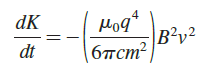
It is shown in more advanced courses that charged particles in circular orbits radiate electromagnetic waves, called cyclotron radiation. As a result, a particle undergoing cyclotron motion with speed v is actually losing kinetic energy at the rate How long does it take (a) An electron (b) A
A Hall-effect probe to measure magnetic field strengths needs to be calibrated in a known magnetic field. Although it is not easy to do, magnetic fields can be precisely measured by measuring the cyclotron frequency of protons. A testing laboratory adjusts a magnetic field until the proton’s
A particle of charge q and mass m moves in the uniform fields E = E0 k̂ and B = B0 k̂. At t = 0, the particle has velocity v0 = v0 î. What is the particle’s speed at a later time t?
Particle accelerators, such as the Large Hadron Collider, use magnetic fields to steer charged particles around a ring. Consider a proton ring with 36 identical bending magnets connected by straight segments. The protons move along a 1.0-m-long circular arc as they pass through each magnet. What
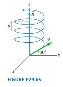
The uniform 30 mT magnetic field in FIGURE P29.65 points in the positive z-direction. An electron enters the region of magnetic field with a speed of 5.0 × 10⁶m/s and at an angle of 30° above the xy-plane. Find the radius r and the pitch p of the electron€™s spiral
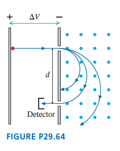
FIGURE P29.64 shows a mass spectrometer, an analytical instrument used to identify the various molecules in a sample by measuring their charge-to-mass ratio q/m. The sample is ionized, the positive ions are accelerated (starting from rest) through a potential difference ΔV, and
An antiproton is identical to a proton except it has the opposite charge, -e. To study antiprotons, they must be confined in an ultrahigh vacuum because they will annihilate—producing gamma rays—if they come into contact with the protons of ordinary matter. One way of confining antiprotons is
a. A 65-cm-diameter cyclotron uses a 500 V oscillating potential difference between the dees. What is the maximum kinetic energy of a proton if the magnetic field strength is 0.75 T?b. How many revolutions does the proton make before leaving the cyclotron?
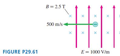
An antiproton (same properties as a proton except that q = -e) is moving in the combined electric and magnetic fields of FIGURE P29.61. What are the magnitude and direction of the antiproton€™s acceleration at this instant? B= 2.5 T 500 m/s- E = 1000 V/m FIGURE P29.61
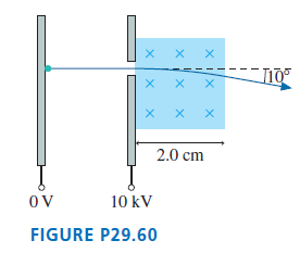
An electron in a cathode-ray tube is accelerated through a potential difference of 10 kV, then passes through the 2.0 cm-wide region of uniform magnetic field in FIGURE P29.60. What field strength will deflect the electron by 10°? 2.0 cm OV 10 kV FIGURE P29.60 X IX
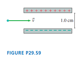
An electron travels with speed 1.0 × 10⁷m/s between the two parallel charged plates shown in FIGURE P29.59. The plates are separated by 1.0 cm and are charged by a 200 V battery. What magnetic field strength and direction will allow the electron to pass between the plates without being
A proton moving in a uniform magnetic field with v1 = 1.00 × 10⁶ î m/s experiences force F1 = 1.20 × 10⁻¹⁶ k̂ N. A second proton with v2 = 2.00 × 10⁶ ĵ m/s experiences F2 = -4.16 × 10⁻¹⁶ k̂ N in the same field. What is B? Give your answer as a magnitude and an angle measured ccw from the
A long, hollow wire has inner radius R1 and outer radius R2. The wire carries current I uniformly distributed across the area of the wire. Use Ampère’s law to find an expression for the magnetic field strength in the three regions 0 < r < R1, R1 < r < R2, and R2 < r.
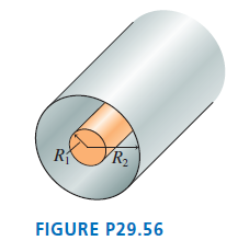
The coaxial cable shown in FIGURE P29.56 consists of a solid inner conductor of radius R1surrounded by a hollow, very thin outer conductor of radius R2. The two carry equal currents I, but in opposite directions. The current density is uniformly distributed over each conductor. a. Find expressions
Showing 1400 - 1500
of 3693
First
8
9
10
11
12
13
14
15
16
17
18
19
20
21
22
Last
Step by Step Answers