New Semester
Started
Get
50% OFF
Study Help!
--h --m --s
Claim Now
Question Answers
Textbooks
Find textbooks, questions and answers
Oops, something went wrong!
Change your search query and then try again
S
Books
FREE
Study Help
Expert Questions
Accounting
General Management
Mathematics
Finance
Organizational Behaviour
Law
Physics
Operating System
Management Leadership
Sociology
Programming
Marketing
Database
Computer Network
Economics
Textbooks Solutions
Accounting
Managerial Accounting
Management Leadership
Cost Accounting
Statistics
Business Law
Corporate Finance
Finance
Economics
Auditing
Tutors
Online Tutors
Find a Tutor
Hire a Tutor
Become a Tutor
AI Tutor
AI Study Planner
NEW
Sell Books
Search
Search
Sign In
Register
study help
physics
process dynamics control
Process Dynamics And Control 4th Edition Dale E. Seborg, Thomas F. Edgar, Duncan A. Mellichamp, Francis J. Doyle - Solutions
An electronic PID temperature controller is at steady state with an output of 12 mA. The set point equals the nominal process temperature initially. At t = 0, the error signal is increased at the rate of 0.5 mA/min (equivalent to a rate of 2∘F/min). If the current settings areKc = 2
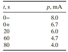
An electronic PI temperature controller has an output p of 12 mA when the set point equals the nominal process temperature. The controller response to step change in the temperature set point of 2.5 mA (equivalent to a change of 5ˆ˜F) is shown below:Determine the controller gain Kc
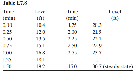
Consider the PCM furnace module of Appendix E. Assume that hydrocarbon temperature THCis the output variable and that air flow rate FAis the input variable.(a) Develop an FOPTD model from response data for a step change in FA at t = 10 min from 17.9 to 20.0 m3/min. Summarize your calculated model
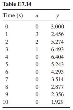
Data for a person with type 1 diabetes are available as both MATLAB and Excel data files on the book web site. 1 Glucose measurements (y) were recorded every five minutes using a wearable sensor that measures subcutaneous glucose concentration. The insulin infusion rate (u) from a wearable
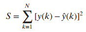
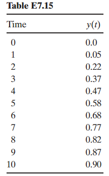
Unit step response data are given in Table E7.15 for a process with gain K = 2. Fit the data to a first order model with no time delay. Next use linear regression to fit a first-order discrete-time equation to the data with Δt = 1. Then plot the predicted value of y(t) for both models
The following data were collected from a cell concentration sensor measuring absorbance in a biochemical stream. The input u is the flow rate deviation (in dimensionless units) and the sensor output y is given in volts. The flow rate (input) is piece wise constant between sampling instants. The
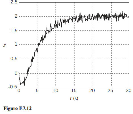
Fig. E7.12 presents the response of a system to a unit step in the input.(a) Use these data to derive an FOPTD model of this system.(b) Plot the response of the model and compare with the data.(c) The FOPTDmodel does not capture all the features of the original response. What is the feature that
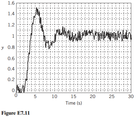
The response of a system to a unit step change in the input (occurring at time 0) is shown in Fig. E7.11.(a) Derive a second-order plus time delay model approximation for the system. Provide values for the gain, time constraints, and time delay of the SOPTD model.(b) Why would a FOPTD model not be
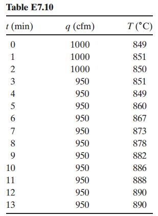
Noisy data for the step response of a boiler temperature T to a decrease in air flow rate q from 1000 to 950 cfm are shown below. Develop a FOPTD model using a method from Chapter 7. Be sure to use deviation variables and report units for the model parameters. Table E7.10 q (cfm) T (°C) t (min)
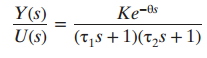
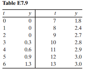
The output response data y shown in Table E7.9 were generated from a step change in input u from 1 to 5 at time t = 0. Develop a transfer function model of the form Y(s) Ke-0s (T,8 +1)(t,s + 1) U(s) Table E7.9 y t y 1.8 2.4 2.7 3 0.3 10 2.8 4 0.6 11 2.9 0.9 12 3.0 1.3 13 3.0
The level in a tank responds as a first-order system to changes in its inlet flow. The data shown below were gathered after the inlet flow was increased quickly from 1.5 to 4.8 gal/min.(a) Determine the transfer function by estimating the time constant using one of the methods of Section 7.2. Be
Assume that step response data obtained from an FOPTD system with K = τ = 1 are available. Determine the accuracy of the FOPTD approximate model derived from these data using the Sundaresan and Krishnaswamy method, and consider three cases: θ/τ = 0.1, 1.0, 10.0. Plot the results and calculate
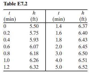
A single-tank process has been operating for a long period of time with the inlet flow rate qi equal to 30.1 ft3/min. After the operator increases the flow rate suddenly at t = 0 by 10%, the liquid level in the tank changes as shown in Table E7.2. Assuming that the process dynamics can be
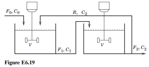
Consider the following cascade connection of isothermal reactors. A first-order reaction A †’ B occurs in both reactors, with reaction rate constant k. The volumes of liquid in the reactors,V, are constant and equal; the flow rates F0, F1, F2and R are constant. Assume constant physical
Example 5.1 derives the gain and time constant for a first-order model of a stirred tank heating process. (a) Simulate the response of the tank temperature to a step change in heat input from 3×10⁷ cal/h to 5×10⁷ cal/h.(b) Suppose there are dynamics associated with changing the heat input to
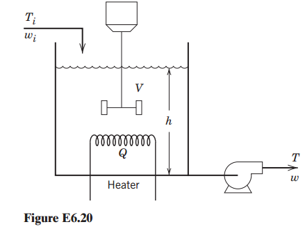
A two-input / two-output process involving simultaneous heating and liquid-level changes is illustrated in Fig. E6.20. Find the transfer function models and expressions for the gains and the time constant Ï„ for this process. What is the output response for a unit step change in Q for a
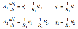
The system equations for two liquid surge tanks in series areUsing state-space notation, determine the matrices A, B, C, and E, assuming that the level deviations is h€²1 and h€²2 are the state variables, the input variable is q€²1, and the output variable is the flow
An operator introduces a step change in the flow rate qi to a particular process at 3:05 A.M., changing the flow from 500 to 520 gal/min. The first change in the process temperature T (initially at 120∘F) occurs at 3:08 A.M. After that, the response in T is quite rapid, slowing down gradually
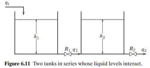
Show that the liquid-level system consisting of two interacting tanks (Fig. 6.11) exhibits over damped dynamics; that is, show that the damping coefficient in Eq. 6-57 is larger than one. di h2 hi R2 92 Rị 41 Figure 6.11 Two tanks in series whose liquid levels interact.
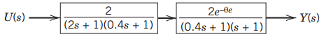
A process has the block diagramDerive an approximate first order plus time delay transfer function model. 2e-de Y(s) |U(s)· (2s + 1)(0.4s + 1) (0.4s + 1)(s + 1)
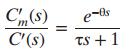
composition analyzer is used to measure the concentration of a pollutant in a wastewater stream. The relationship between the measured composition Cm and the actual composition C is given by the following transfer function (in deviation variable form): where θ = 2 min and
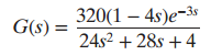
Consider the transfer function(a) What are the gain, time delay, time constants, poles, and zeros of G(s)?(b) Will the step response of this transfer function exhibit (i) inverse response or (ii) oscillations? 320(1 – 4s)e-3s G(s) = 24s2 + 28s + 4
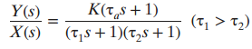
The transfer function relating the blood pressure of a patient to the infusion rate of a blood pressure drug is given bywhere θ1 = 30 s, θ2 = 45 s, and τ1 = 40 s. Sketch the unit step response of this system. Show an approximate time axis and all
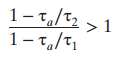
Consider a process model:For a step input, show that:(a) y(t) can exhibit an extremum (maximum or minimum value) in the step response only if(b) Overshoot occurs only for Ï„a/Ï„1 > 1.(c) Inverse response occurs only for Ï„a < 0.(d) If an extremum in y
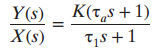
For a lead€“lag unit,show that for a step input of magnitude M:(a) The value of y at t = 0+ is given by y(0+) = KM Ï„a/Ï„1.(b) Overshoot occurs only for Ï„a > Ï„1.(c) Inverse response occurs only for Ï„a < 0. K(t,s+1) Y(s)
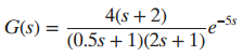
The following transfer function is not written in a standard form:(a) Put it in standard gain/time constant form.(b) Determine the gain, poles and zeros.(c) If the time-delay term is replaced by a 1/1 Pade approximation, repeat part (b). 4(s + 2) -5s |G(s) = (0.5s + 1)(2s + 1)*
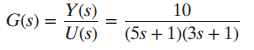
Consider the transfer functionWhat is y(t †’ ˆž) for the following inputs:(a) Step input of height M(b) Unit impulse input δ(t)(c) Sin t(d) Unit rectangular pulse (Eq. 3-13, h = 1) Y(s) 10 + 1) G(s) = (5s + 1)(3s U(s)
A heater for a semiconductor wafer has first-order dynamics, that is, the transfer function relating changes in temperature T to changes in the heater input power level P iswhere K has units [ˆ˜C/Kw] andÏ„has units [min].The process is at steady state when an engineer changes
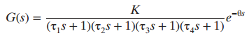
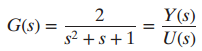
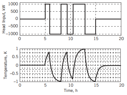
Consider the fourth-order plus time delay system represented below:Assume that a step change is applied in the system input U(s). Will the time required for the output Y(s) to reach steady state depend on the magnitude of the step input in U? Explain. G(s) = K -Os (t,s + 1)(t,s + 1)(T38 + 1)(t,s +
A tank used to dampen liquid flow rate surges is known to exhibit second-order dynamics. The input flow rate changes suddenly from 180 to 210 gal/min. An operator notes that the tank level changes as follows:Before input change: level =10 ft and steady Four minutes later: level =
A process has the transfer function(a) For a step change in the input U(s) = 2/s, sketch the response y(t) (you do not need to solve the differential equation). Show as much detail as possible, including the steady-state value of y(t), and whether there is oscillation.(b) What is the decay ratio?
Using the step responses of (1) an integrating element and (2) a first-order process to an input change of magnitude M. (a) Show that the step response for an input change M of a first-order process G1(s) = K1 / τs + 1can be approximately modeled by the step response of an integrator.G0(s) =
For a stirred-tank heater, assume the transfer function between the heater input change u(t) (cal/sec) and the tank temperature change y(t)(∘C) can be modeled as G(s) = 5 / 3s + 1 (a) Using the Final Value Theorem, find the steady-state response for a unit rectangular pulse change in the
An additive process model is depicted in the figure below. For (unit impulse) (a) Derive the response Y(s) and describe y(t) quantitatively.(b) Simulate the response and identify its major characteristics. G = -3 U(s) = 1 G, = ÷, G, = 2s +1' %3D s+1° G1 G2 G3
Can a tank with the outflow rate fixed by a constant speed pump reach a steady state if the inlet flow rate undergoes a step change? Why, or why not? If the transfer function is G(s) = K/s, is it possible to calculate a steady-state gain?
A thermometer with first-order time constant = 0.1 min and gain = 1.0 is placed in a temperature bath (25∘C). After the thermometer comes to equilibrium with the bath, the temperature of the bath is increased linearly at a rate of 1∘ /min. (a) What is the difference between the measured
A thermometer has first-order dynamics with a time constant of 1 sec and is placed in a temperature bath at 120∘F. After the thermometer reaches steady state, it is suddenly placed in a bath at 140∘ F for 0 ≤ t ≤ 10 sec. Then it is returned to the bath at 100∘F.(a) Sketch the variation of
Show that when K = 1, the ramp response of the third-order system G(s)= K / (τs+1)3 lags behind the input signal (u = at) by three time constants, once the output is changing linearly in time.
A vertical, cylindrical tank is filled with water at 20∘C. The tank is insulated at the top and bottom, with diameter of 0.5 m and height of 1.0 m. The overall heat transfer coefficient is U = 120 W/m2 K. The density of water is ρ = 1000 kg/m3 ,the heat capacity Cp = 4180 J/kgK, the melting
An operator tests the dynamic behavior of a furnace in order to identify the transfer function relating the furnace temperature (output) to the heat input. The operator performs a series of step increases / decreases in the amount of heat input and records the temperature changes in the furnace.
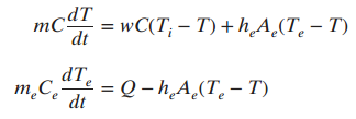
onsider the model of the electrically heated stirred-tank system in Section 2.4.3. Subscript e refers to the heating element:(a) Derive transfer functions relating changes in outlet temperature T to changes in the two input variables: heater input Q(assuming no change in inlet temperature), and
A stirred-tank blending system can be described by a first-order transfer function between the exit composition x and the inlet composition x1 (both are mass fractions of solute):X′(s) / X′i (s) = K / τs + 1where K = 0.6 (dimensionless) and τ = 10 min. When the blending system is at
Consider the transfer function model in Exercise 4.2. For an initial condition of y(0) = 4 and a step change in u of magnitude 2 (at t = 0), calculate the response, y(t).
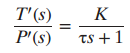
The dynamic behavior of a pressure sensor / transmitter can be expressed as a first-order transfer function (in deviation variables) that relates the measured value Pm to the actual pressure, P:P′m(s) / P′(s) = 1 / 30s + 1Both Pm and P have units of psi and the time constant has units of
Consider the following transfer function:G(s)= Y(s) / U(s) = 3e−s / 10s + 1(a) What is the steady-state gain?(b) What is the time constant?(c) If U(s) = 4/s, what is the value of the output y(t) when t → ∞?(d) For the same input, what is the value of the output when t = 10? What is the output
Consider a transfer function:Y(s)/U(s) = d/bs + c(a) What is the steady-state gain?(b) For a step change of magnitude Min the input, will the output response be bounded for all values of constants b,c and d? Briefly justify your answer.
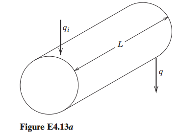
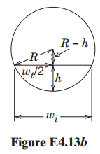
A horizontal cylindrical tank shown in Fig. E4.13a is used to slow the propagation of liquid flow surges in a processing line. Figure E4.13b illustrates an end view of the tank and wtis the width of the liquid surface, which is a function of its height, both of which can vary with time. Develop a
Solve this ODE using a Symbolic software program:All initial conditions for y and its derivatives are zero. d'y dềy + 16y 176 + 105y = 1 + 86y dt? dr dt di3 dt
For the three stirred-tank system of Exercise 3.20 (Part (b)1), use symbolic system software to find the exit con-centration of tank 3, c3(t), after a rectangular pulse in ci(t) occurs at t = 0. The pulse magnitude is A and the pulse width is tw. M Ci м м сз V1 V2 V3
Three stirred-tanks in series are used in a reactor train (see Fig. E3.20). The flow rate into the system of some inert species is maintained constant while tracer tests are conducted. Assuming that mixing in each tank is perfect and the volumes are constant: (a) Derive expressions for the
A liquid storage facility can be modeled bywhere y is the liquid level (m) and u is an inlet flow rate (m3/s). Both are defined as deviations from the nominal steady-state values. Thus, y = u = 0 at the nominal steady state. Also, the initial values of all the derivatives are zero. (a) If u(t)
A continuous, stirred-tank reactor is initially full of water with the inlet and exit volumetric flow rates of water having the same numerical value. At a particular time, an operator shuts off the water flow and adds caustic solution at the same volumetric flow rate q, but with concentration
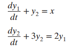
Use Laplace transforms to find the solution to the following set of equationsfor x = eˆ’t and zero initial conditions. dy + У2 %3D х dt dy2 + Зу, 3 2у, dt 2y1
For the equation,Use the partial fraction method, to find y(t). ÿ + 5ỷ + 6y(t) = 7, ý(0) = 0, y(0) = 1
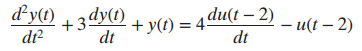
The dynamic model between an output variable y and an input variable u can be expressed by(a) Does this system exhibit an oscillatory response after an arbitrary change in u?(b) What is the steady-state value of y when u(tˆ’2)= 1?(c) For a step change in u of magnitude 1.5, what is y(t)?
The dynamic model for a process is given by where u(t) is the input function and y(0) and dy/dt (0) are both zero.What are the functions of the time (e.g., eˆ’t/Ï„) in the solution for each of the following cases?(a) u(t) = beˆ’2t(b) u(t) = ctb and c are
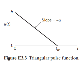
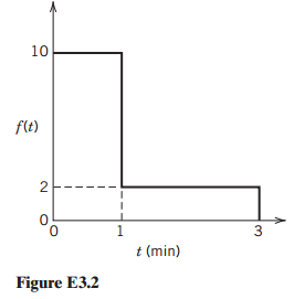
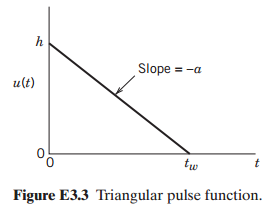
Figure E3.3 shows a pulse function,u(t).(a) From the information shown in Fig. 3.3, calculate the pulse width, tw.(b) Express u(t) as the sum of simpler functions (some perhaps translated in time), whose transforms can be obtained from Table 3.1.(c) Find U(s).(d) What is the area under the
Derive Laplace transforms of the input signals shown in Figs. E3.2 and E3.3 by summing component functions found in Table 3.1. 10 f(t) 3 t (min) Figure E3.2 Slope = -a u(t) tw Figure E3.3 Triangular pulse function.
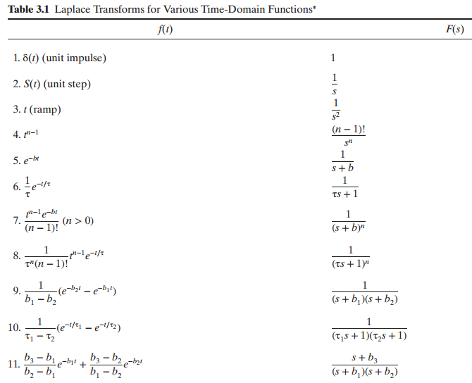
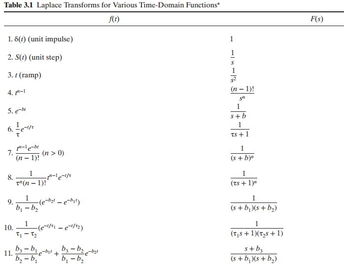
Find the Laplace transforms of the following functions, using the information in Table 3.1. (However, some of the individual terms in these functions may not have Laplace transforms.)(a) f(t) = 5 + eˆ’3t + teˆ’4t(b) f(t) = sin(4t) + t ˆ’ 3 +
Consider the PCM distillation column module of Appendix E, in which a 50%–50% mixture of methanol (MeOH) and ethanol is separated.Do the following sequence of simulations:(a) Change the Vapor Flow Rate from the initialized value to a new value of 0.045 m3 /s, and start the simulation. Generate
Consider the PCM Furnace module of Appendix E, which is used to preheat a high-molecular-weight hydro-carbon feed (C16 – C26) to a cracking unit at a petroleum refinery.Do the following sequence of simulations:(a) Change the Fuel Gas Purity from the initialized value of 1.0 to a new value of
Plot the level response for a tank with constant cross-sectional area of 4 ft2 as a function of time for the following sequence of events; assume an initial level of 1.0 ft with the drain open, and that level and outflow rate are linearly related. The steady-state inflow and outflow are initially
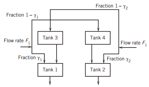
Consider the unusual piping diagram for the four tanks in Fig. E2.22 in which both the flow rates F1and F2are split between two streams entering the upper and lower tanks (denoted by the fractions in the diagram). For the exit lines leaving the bottom of each of the four tanks through an orifice,
Perform a degrees of freedom analysis for the model in Eqs. 2-64 through 2-68. Identify parameters, output variables, and inputs (manipulated and disturbance variables).
Example 2.1 plots responses for changes in input flows for the stirred tank blending system. Repeat part (b) and plot it. Next, relax the assumption that V is constant, and plot the response of x(t) and V(t) for the change in w1 for t = 0 to 15 minutes. Assume that w2 and w remain constant.
Sketch the level response for a bathtub with cross-sectional area of 8ft2 as a function of time for the following sequence of events; assume an initial level of 0.5 ft with the drain open. The inflow and outflow are initially equal to 2ft3 /min.(a) The drain is suddenly closed, and the inflow
Recall the stirred-tank heating process with variable holdup as described in Section 2.4.2. Recalculate the degrees of freedom for this example under the following separate circumstances (be sure to explain clearly your outputs, manipulated inputs, and disturbance inputs):(a) The flow rate exiting
Showing 100 - 200
of 167
1
2
Step by Step Answers