New Semester
Started
Get
50% OFF
Study Help!
--h --m --s
Claim Now
Question Answers
Textbooks
Find textbooks, questions and answers
Oops, something went wrong!
Change your search query and then try again
S
Books
FREE
Study Help
Expert Questions
Accounting
General Management
Mathematics
Finance
Organizational Behaviour
Law
Physics
Operating System
Management Leadership
Sociology
Programming
Marketing
Database
Computer Network
Economics
Textbooks Solutions
Accounting
Managerial Accounting
Management Leadership
Cost Accounting
Statistics
Business Law
Corporate Finance
Finance
Economics
Auditing
Tutors
Online Tutors
Find a Tutor
Hire a Tutor
Become a Tutor
AI Tutor
AI Study Planner
NEW
Sell Books
Search
Search
Sign In
Register
study help
engineering
electrical engineering
Basic Engineering Circuit Analysis 9th Edition J. David Irwin - Solutions
A field-oriented drive system will be applied to a 230-V, 20-kW, four-pole, 60-Hz induction motor which has the following equivalent-circuit parameters in ohms per phase referred to the stator: Rl = 0.0322 R2 = 0.0703 X1 = 0.344 X2 = 0.353 Xm = 18.6. The motor is connected to a load whose torque
a. The value of the peak direct- and quadrature-axis components of the armature currents iD and iQ.b. The rms armature current under this operating condition.c. The electrical frequency of the drive in Hz.d. The rms line-to-line armature voltage. Discuss.
A three-phase, eight-pole, 60-Hz, 4160-V, 1250-kW squirrel-cage induction motor has the following equivalent-circuit parameters in ohms-per-phase-Y referred to the stator: R1 = 0.212 R2 = 0.348 X1 = 1.87 X2 = 2.27 Xm = 44.6. It is operating from a field-oriented drive system at a speed of 805r/min
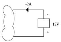
Determine whether the element in figure is absorbing or supplying power and how much.
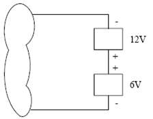
In figure, element 2 absorbs 24W of power. Is element 1 absorbing or supplying power and howmuch.
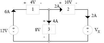
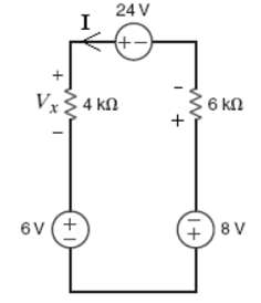
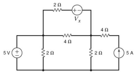
Given the network in figure find the value of the unknown voltageVX
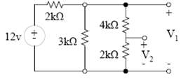
Determine the voltages V1 and V2 in the network in figure using voltagedivision.
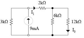
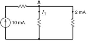
Find the currents I1 and I0 in the circuit in figure using currentdivision.
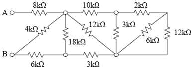
Find the resistance of the network in figure at the terminalsA-B.
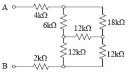
Find the resistance of the network shown in figure at the terminalsA-B.
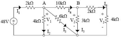
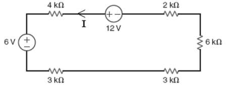
Find all the currents and voltages in the network infigure.
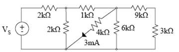
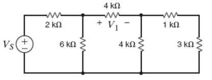
In the network in figure, the current in the 4k? resistor is 3mA. Find the input voltage VS.
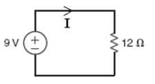
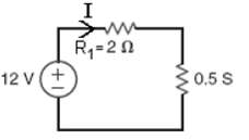
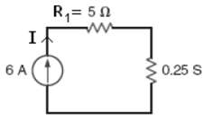
Determine the current and power dissipated in the resistor in figure.
Determine the current and power dissipated in the resistors in figure.
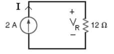
Determine the voltage across the resistor in figure and the powerdissipated.
Given the circuit in figure, find the voltage across each resistor and the power dissipated in each.
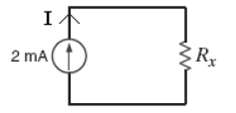
In the network in figure, the power absorbed by Rx is 20mW. Find Rx.
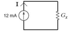
In the network in figure, the power absorbed by Gx is 20mW. FindGx.
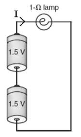
A model for a standard two D-cell flashlight is shown in Figure. Fine the power dissipated in thelamp.
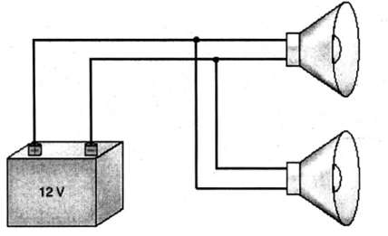
An automobile uses two halogen headlights connected as shown in Figure. Determine the supplied by the battery if each headlight draws 3A ofcurrent.
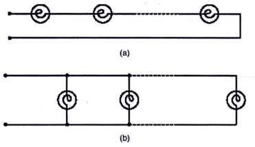
Many years ago a string of Christmas tree lights was manufactured in the form shown in Figure a. Today the lights are manufactured as shown in Figure b. Is there a good reason for thischange?
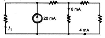
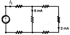
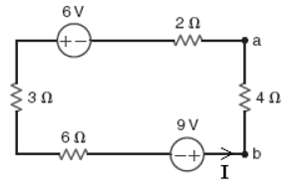
Find I1 in the network infigure.
Fin I1 in the network infigure.
Find I1 in the network infigure.
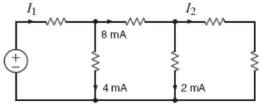
Find I1 and I2 in the circuit infigure.
Find I1, in the circuit infigure.
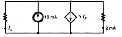
Find Ix in the circuit infigure.
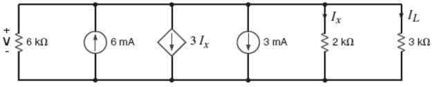
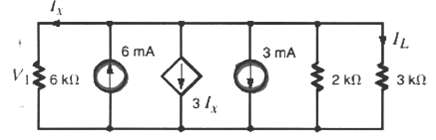
Determine IL in the circuit infigure.
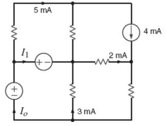
Find I0 and I1 in the circuit infigure.
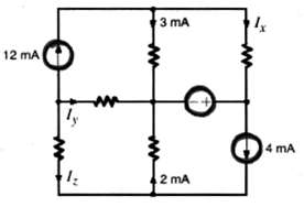
Find Ix, Iy, and Iz in the network infigure.
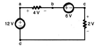
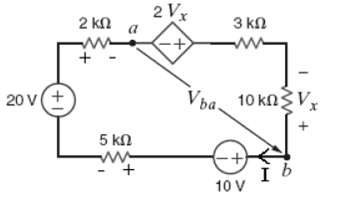
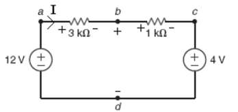
Find Vbd in the circuit infigure.
Find Vad in the network infigure.
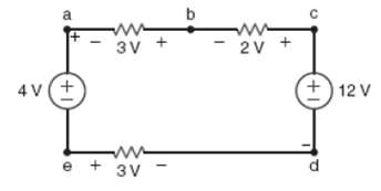
Find Vfb and Vec in the circuit infigure.
Find Vae and Vcf in the circuit infigure.
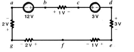
Given the circuit diagram in figure, find the following voltages: Vda, Vbh, Vgc, Vfa, Vac, Vai, Vhf, and Vdc,
Find Vac in the circuit infigure:
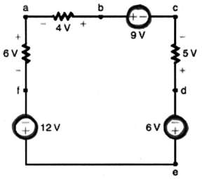
Find Vad and Vce in the circuit infigure:
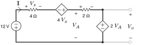
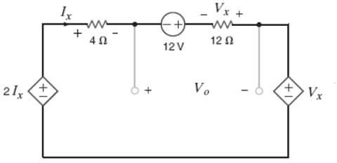
Find Vo in the network infigure.
Find Vo in the circuit infigure.
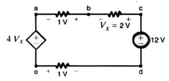
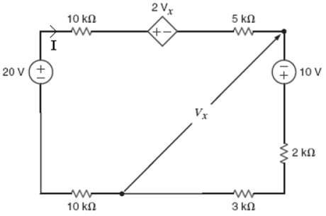
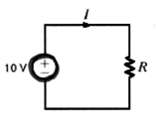
The 10-V source absorbs 2.5mW of power. Calculate Vba and the power absorbed by the dependent voltage source in figure.
Find Vbd in the network infigure.
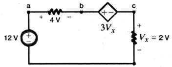
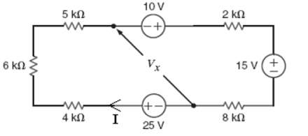
Find Vx in the circuit infigure.
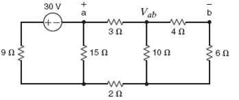
Find Vab in the network infigure.
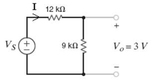
If Vo = 3V in the circuit in figure, findVS.
Find the power supplied by each source in the circuit inFigure.
Find Vx and the power supplied by the 15-V source in the circuit infigure.
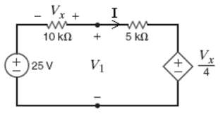
Find V1 in the network infigure.
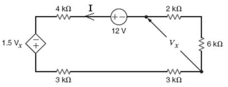
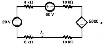
Calculate the power absorbed by the dependent source in the circuit infigure.
Find the power absorbed by the dependent voltage source in the circuit infigure.
Find the power absorbed by the dependent source in the circuit infigure.
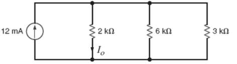
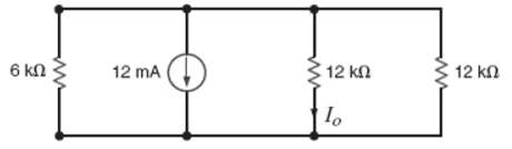
Find I0 in the network in figure.
Find I0 in the network in Figure.
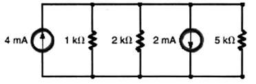
Find the power supplied by each source in the circuit in Figure.
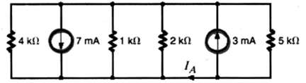
Find the current IA in the circuit infigure.
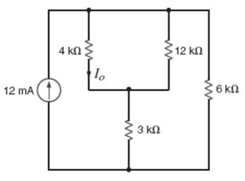
Find I0 in the network in figure.
Find I0 in the network infigure.
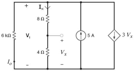
Calculate the power absorbed by the dependent source in the circuit infigure.
Determine I1 in the circuit infigure.
Find the power absorbed by the dependent source in the network infigure.
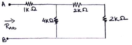
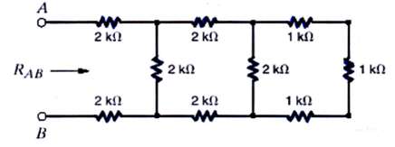
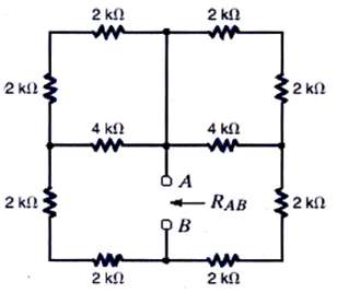
Find RAB in the circuit in figure.
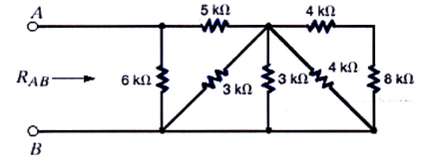
Find RAB in the network in figure.
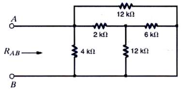
Find RAB in the circuit in figure.
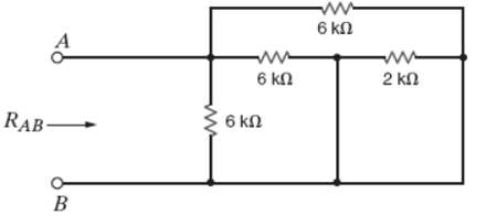
Find RAB in the network in figure.
Find RAB in the circuit in figure.
Find RAB in the network in figure.
Find RAB in the circuit in figure.
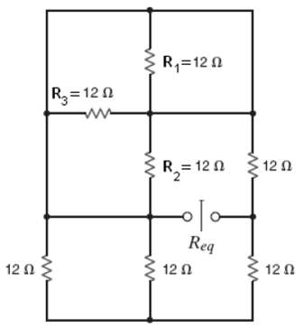
Find the equivalent resistance Req in the network in Figure.
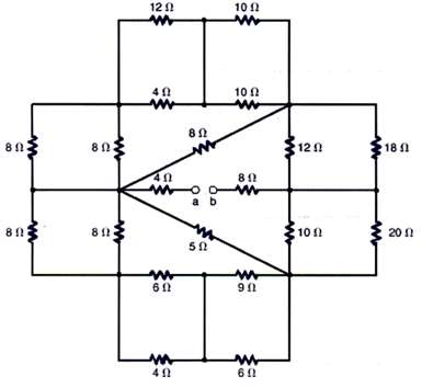
Find the equivalent resistance looking in at terminals a-b in the circuit in figure.
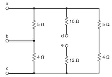
Given the resistor configuration shown in figure, find the equivalent resistance between the following sets of terminals:? (1) A and b,? (2) B and c,? (3) A and c,? (4) D and e,? (5) A and e,? (6) C and d,? (7) A and d,? (8) C and e,? (9) B and d, and? (10) B ande,
Seventeen possible equivalent resistance values may be obtained using three resistors. Determine the seventeen different values if you are given resistors with standard values 47Ω, 33Ω, and 15Ω.
Find the range of resistance for the following resistors.(a) 1k Ω with a tolerance of 5%(b) 470 Ω with a tolerance of 2%(c) 22k Ω with a tolerance of 10%
Given the network in figure, find the possible range of values for the current and power dissipated by the following resistors. (a) 390 ? with a tolerance of 1%. (b) 560 ? with a tolerance of 2%.
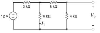
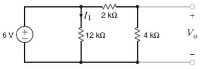
Find I1 and V0 in the circuit infigure.
Find I1 and V0 in the circuit infigure.
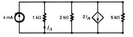
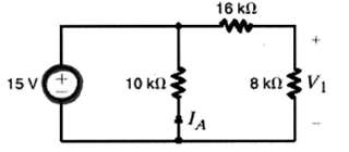
Find V1 and IA in the network infigure.
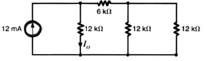
Find I0 in the network in figure.
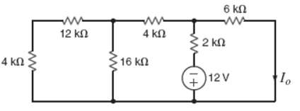
Determine I0 in the circuit in figure.
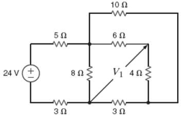
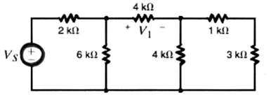
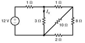
Find V1 in the network in figure.
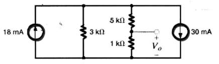
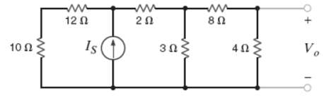
Determine V0 in the network infigure.
Find Vab in the circuit infigure.
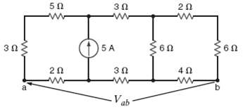
Find V ab in the network infigure.
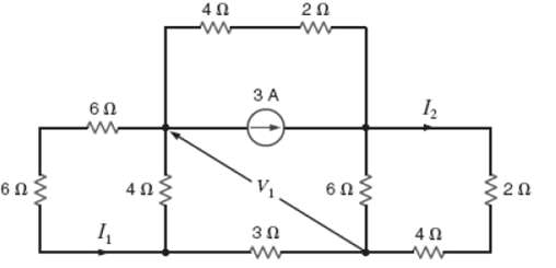
Find I1, I2 and V1 in the circuit in figure.
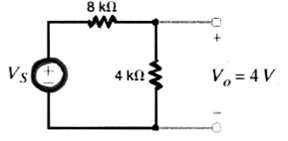
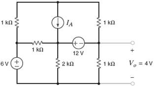
If Vo = 4V in the network in figure, findVs.
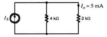
If Io = 5 mA in the circuit in figure andIS.
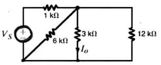
If Io = 2 mA in the circuit in figure, find VS.
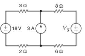
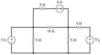
Find the value of VS in the network in figure such that the power supplied by the current source is 0.
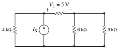
In the network in figure, V1 = 12V, find VS.
In the network in figure, Vo = 6V, findIS.
In the circuit in figure, V0 = 2V. FindIS.
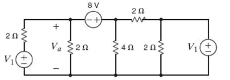
Find the value of V1 in the network in figure, such that Va =0.
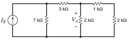
If V1 = 5V in the circuit in figure, find IS.
In the network in figure, V1 = 12V, find VS.
Find the value of Vx in the network in figure, such that the 5-A current source supplies50W.
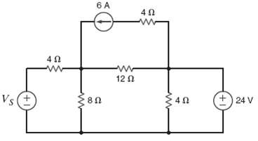
If the power absorbed by the 6-A current source in the circuit in figure is 144W, find VS and the power supplied by the 24-V voltagesource.
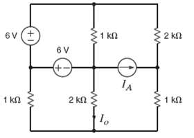
Given Io = 2mA in the circuit in figure, find IA.
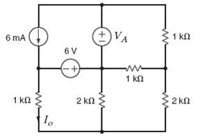
Given Io = 2mA in the network in figure, find VA.
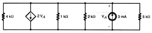
Given Vo in the network in figure, find IA.
If the power supplied by the 2-A current source is 40 W, find VS and the power absorbed by the 5-V source in the network infigure.
Find the current Ix in figure 2PFE-10. a. 1/2A b. 5/3A c. 3/2A d. 8/3A
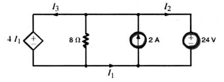
Find I1, I2, and I3 in the circuit infigure.
Showing 1700 - 1800
of 3459
First
11
12
13
14
15
16
17
18
19
20
21
22
23
24
25
Last
Step by Step Answers