New Semester
Started
Get
50% OFF
Study Help!
--h --m --s
Claim Now
Question Answers
Textbooks
Find textbooks, questions and answers
Oops, something went wrong!
Change your search query and then try again
S
Books
FREE
Study Help
Expert Questions
Accounting
General Management
Mathematics
Finance
Organizational Behaviour
Law
Physics
Operating System
Management Leadership
Sociology
Programming
Marketing
Database
Computer Network
Economics
Textbooks Solutions
Accounting
Managerial Accounting
Management Leadership
Cost Accounting
Statistics
Business Law
Corporate Finance
Finance
Economics
Auditing
Tutors
Online Tutors
Find a Tutor
Hire a Tutor
Become a Tutor
AI Tutor
AI Study Planner
NEW
Sell Books
Search
Search
Sign In
Register
study help
engineering
electrical engineering
Basic Engineering Circuit Analysis 9th Edition J. David Irwin - Solutions
Given an op-amp and seven standard 12k? resistors, design an op-amp circuit that will produce an output of
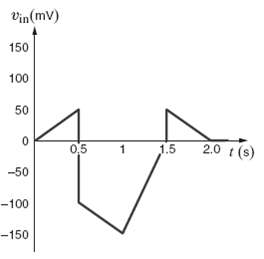
An amplifier has a gain of 15 and the input waveform shown in figure. Draw the outputwaveform.
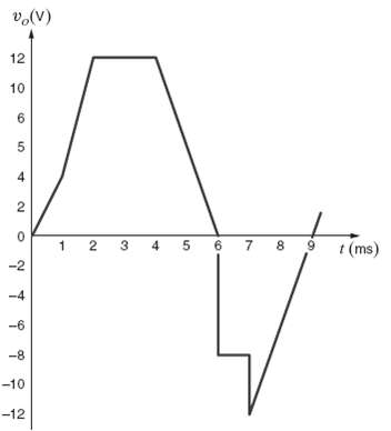
An amplifier has a gain of ? 5 and the output waveform shown in figure sketch the input wave form.
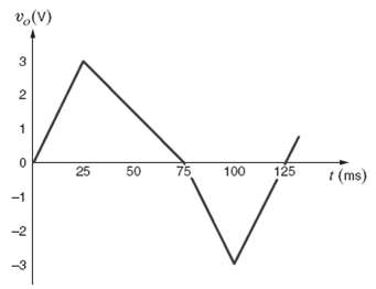
An op-amp based amplifier has supply voltages of ? 5V and a gain of 20. (a) Sketch the input waveform from the output waveform in figure. (b) Double the amplitude of your results in (a) and sketch the new output waveform.
For an ideal op-amp, the voltage gain and input resistance are infinite while the output resistance is zero. What are the consequences for? (a) The op-amp’s input voltage?(b) The op-amp’s input currents?(c) The op-amp’s output current?
Revisit your answers in problem 4.4 under the following non-ideal scenarios.(a) R in = ∞, R out = 0, Ao ≠ ∞(b) R in = ∞, R out = 0, Ao = ∞(c) R in ≠ ∞, R out = 0, Ao = ∞
Revisit the exact analysis of the inverting configuration in section 4.3.(a) Find an expression for the gain if R in = ∞, R out = 0, A o ≠ ∞.(b) Plot the ratio of the gain in (a) to the ideal gain versus Ao for 1 ≤ Ao ≤ 1000 for an ideal gain of – 10.(c) From your plot, does the actual
Revisit the exact analysis of the inverting amplifier in section 4.3.(a) Find an expression for the voltage gain if R in ≠ ∞, R out = 0, Ao ≠ ∞.(b) For R2 = 27kΩ and R1 = 3kΩ, plot the ration of the actual gain to the ideal gain for Ao = 1000 and 1kΩ ≤ 100kΩ.(c) From your plot,
An op-amp based amplifier has ± 18V supplies and a gain of – 80. Over what input range is the amplifier linear?
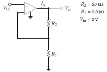
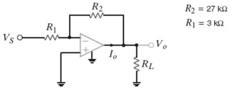
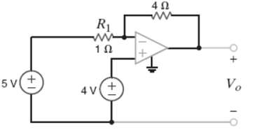
Determine the gain of the amplifier in figure what is the value of Io?
For the amplifier in figure find the gain and Io.
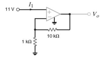
Using the ideal op-amp assumptions, determine the values of Vo and I1 infigure.
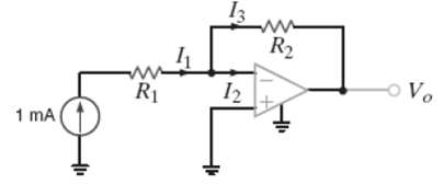
Using the ideal op-amp assumption, determine I1, I2, and I3 infigure.
Repeat problem for the circuit in figure.
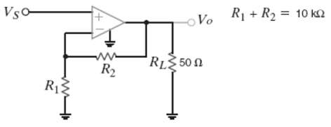
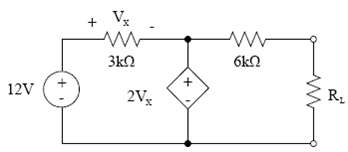
The op-amp in the amplifier in figure operates with ? 15V supplies and can output no more than 200mA. What is the maximum gain allowable for the amplifier if the maximum value of VX is 1 V?
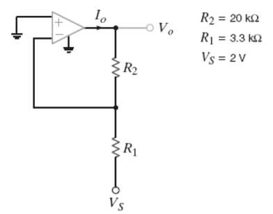
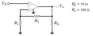
For the amplifier in figure, the maximum value of VS is 2V and the op-amp can deliver no more than 100mA. (a) If ? 10V supplies are used, what is the maximum allowable value of R2? (b) Repeat for ? 3V supplies. (c) Discuss the impact of the supplies on the maximum allowable gain.
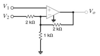
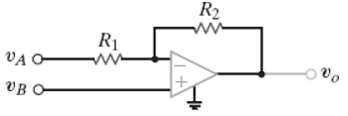
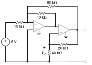
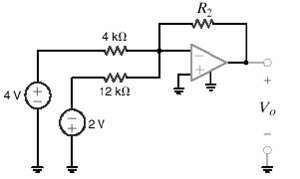
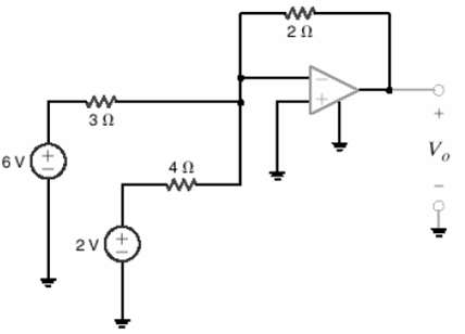
For the circuit in figure (a) Find Vo in terms of V1 and V2. (b) If V1 = 2V and V2 = 6V, find Vo. (c) If the op-amp supplies are ? 12V, and V1 = 4V, what is the allowable range of V2?
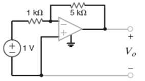
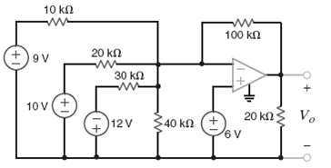
Find Vo in the circuit in figure assuming the op-amp is ideal.
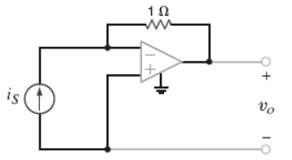
The network in figure is a current-to-voltage converter or trans-conductance amplifier. Find vo/is for thisnetwork.
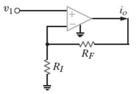
Calculate the transfer function io/v1 for the network shown infigure.
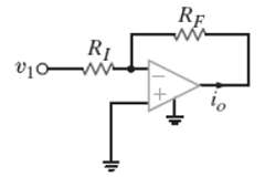
Determine the relationship between v1 and i0 in the circuit shown in figure.
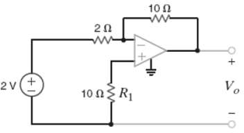
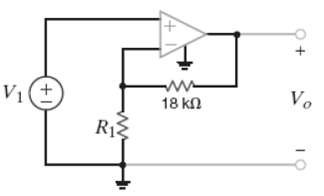
Find Vo in the network in figure and explain what effect R1 has on theoutput.
Determine the expression for Vo in the network infigure.
Show that the output of the circuit infigure.
Find Vo in the network infigure.
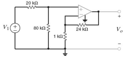
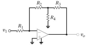
Find the voltage gain of the op-amp circuit shown infigure.
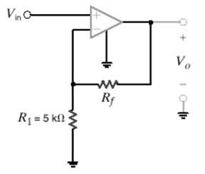
For the circuit in figure find the value of R1 that produces a voltage gain of 10.
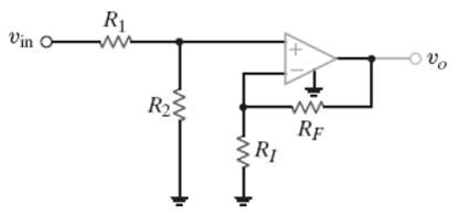
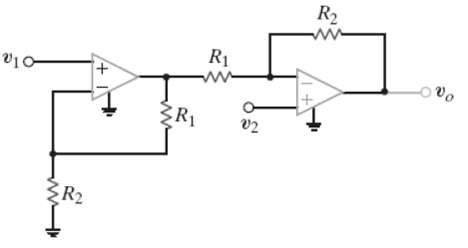
Determine the relationship between vo and vin in the circuit in figure.
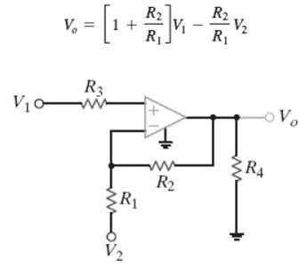
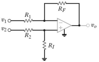
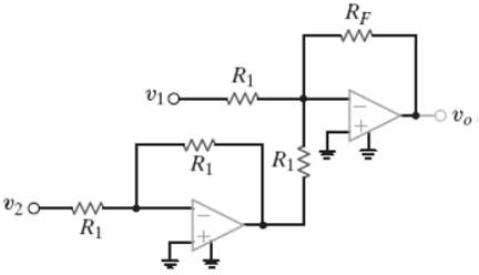
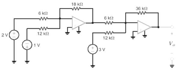
In the network in figure derive the expression for vo in terms of the input v1 and v2.
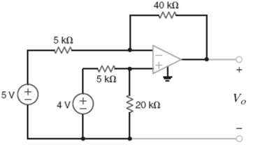
Find Vo in the circuit in figure.
Find Vo in the circuit in figure.
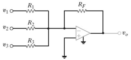
Determine the expression for the output voltage, vo, of the inverting summer circuit shown in figure.
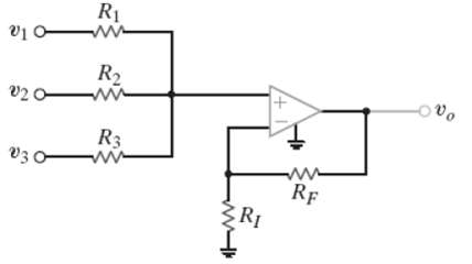
Determine the output voltage vo, of the non-inverting averaging circuit shown in figure.
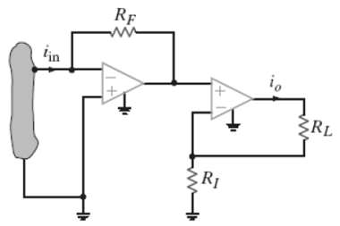
Find the input/output relations for the current amplifier shown in figure.
Find Vo in the circuit in figure.
Find vo in the circuit in figure.
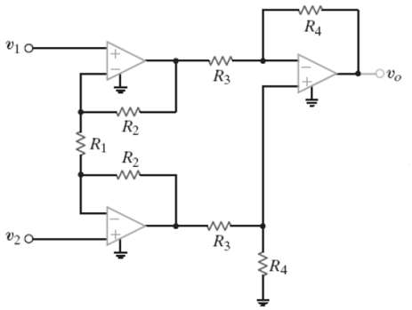
Find the expression for vo in the differential amplifier circuit shown in figure.
Find vo in the circuit in figure.
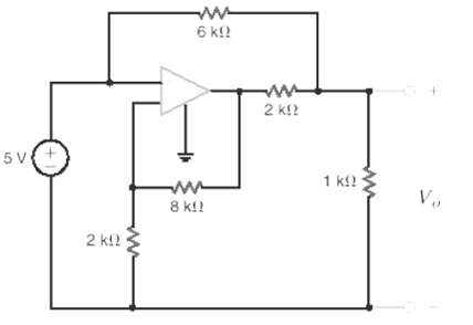
Find the output voltage vo, in the circuit if figure.
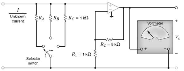
The electronic ammeter in example 4.9 has been modified and is shown in figure. The selector switch allows the user to change the range of the meter. Using values for R1 and R2 from Example 4.9, fine the values of RA and RB that will yield a 10-V output when the current being measured is 100mA and
Given a box of 10-kΩ resistors and an op-amp, design a circuit that will have an output voltage of Vo = – 2V1 – 4V2.
Design an op-amp circuit that has a gain of – 50 using resistors no smaller than 1kΩ.
Design a two-stage op-amp network that has a gain of – 50,000 while drawing no current into its input terminal. Use no resistors smaller than 1kΩ.
Design an op-amp circuit that has the following input/output relationship: Vo = – 5V1 + 0.5V2.
A voltage waveform with a maximum value of 200mV must be amplified to a maximum of 10V and inverted. However, the circuit that produces the waveform can provide no more than 100μA. Design the required amplifier.
An amplifier with a gain of π ± 1 % is needed. Using resistor values from Table 4.1, design the amplifier use as few resistors as possible.
Design an op-amp-based circuit to produce the function. Vo = 5V1 – 4V2
Design an op-amp based circuit to produce the function Vo = 5V1 – 7V2.
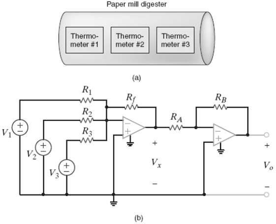
A 170oC maximum temperature digester is used in a paper mill to process wood chips that will eventually become paper. As shown in figure a, three electronic thermometers are placed along its length. Each thermometer outputs 0 V at 0oC, and the voltage changes 25mB/oC. We will use the average of the
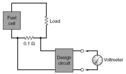
A 0.1-? shunt resistor is used to measure current in a fuel-cell circuit. The voltage drop across the shunt resistor is to be used to measure the current in the circuit. The maximum current is 20 A. Design the circuit shown in figure so that a voltmeter attached to the output will read 0 volts when
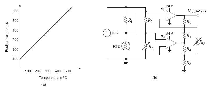
An industrial plant has a requirement for a circuit that uses as input the temperature of a vessel and outputs a voltage proportional to be vessel?s temperature. The vessel?s temperature ranges from 0oC to 5000oC, and the corresponding output of the circuit should range from 0 to 12V. A RTD
Give the summing amplifier shown in figure; select the values of R2 that will produce an output voltage of ? 3V. (a) 4.42k? (b) 6.33k? (c) 3.6k? (d) 5.14k?
What value of Rf in the op-amp circuit of figure is required to produce a voltage gain of 50? (a) 135k? (b) 210k? (c) 180k? (d) 245k?
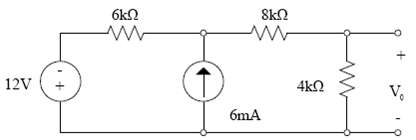
What is the voltage Vo in the circuit in figure. (a) 3V (b) 6V (c) 8V (d) 5V
Determine the output voltage Vo of the summing op-amp circuit shown in figure. (a) 6V (b) 18V (c) 9V (d)10V
What is the output voltage Vo in figure. (a) ? 5v (b) 6V (c) 4V (d) ? 7V
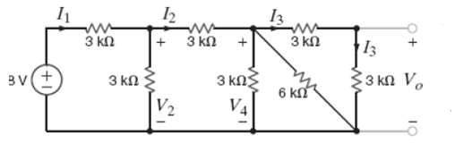
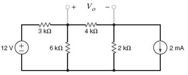
Find V0 in the circuit in figure using the Principle of Super position.
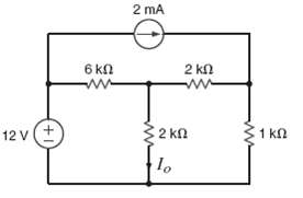
Solve problem 5.1 using source transformation.
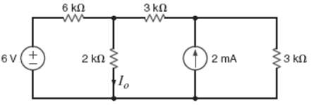
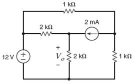
Find V0 in the network in figure using Thevenin?s Theorem.
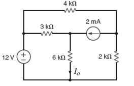
Find I0 in the circuit in figure using Norton?s Theorem.
For the network in figure, find RL for maximum power transfer and the maximum power that can be transferred to this load.
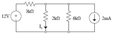
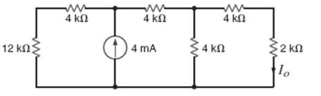
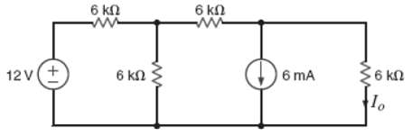
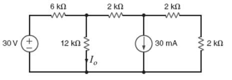
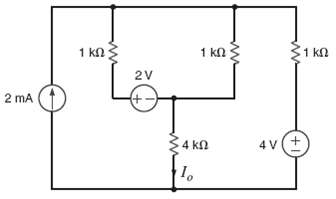
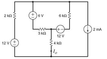
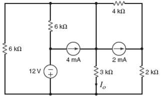
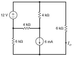
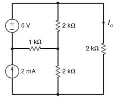
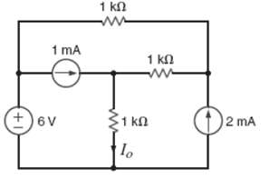
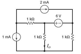
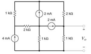
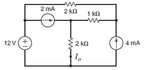
Find Io in the network in figure using linearity and the assumption that Io =1mA.
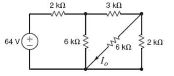
Find Io in the network in figure using linearity and the assumption that Io =1mA.
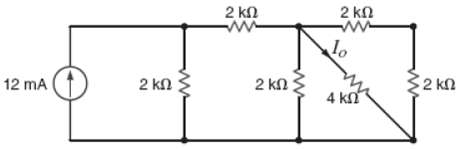
Find Io in the network in figure using linearity and the assumption that Io =1mA.
Find Io in the network in figure using linearity and the assumption that Io =1mA.
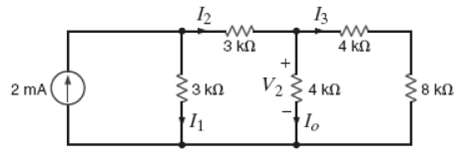
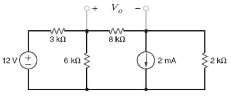
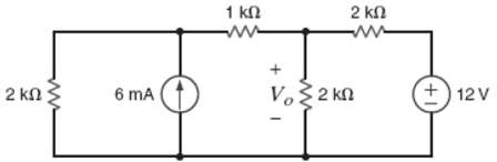
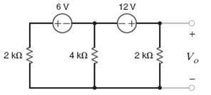
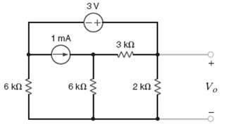
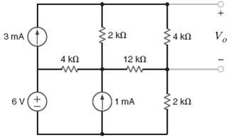
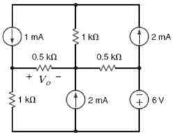
Find Vo in the network in figure using linearity and the assumption that Vo = 1V.
Find Io in the network in figure using super position.
In the network in figure Io using super position
Find Io in the circuit in figure using super position.
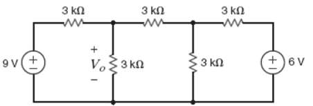
Find Vo in the network in figure using super position.
Find Vo in the network in figure using super position.
Find Vo in the network in figure using super position.
Find Io in the network in figure using super position.
Find Io in the network in figure using super position.
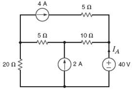
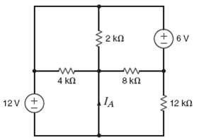
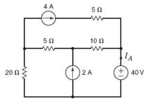
Find IA in the network in figure using super position.
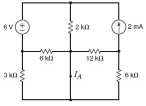
Using superposition, find IA in the circuit in figure.
Find IA in the network in figure in using super position.
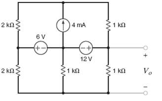
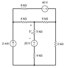
Find Vo in the circuit in figure using super position.
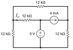
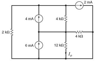
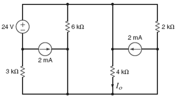
Use superposition to find Io in the network in figure.
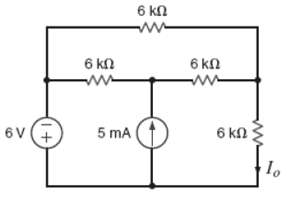
Find Io in the circuit in figure using super position.
Use superposition to find Io in the circuit in figure.
Use superposition to find Io in the circuit in figure.
Use Thevenin?s theorem to find Vo in the network in figure.
Use Thevenin?s theorem to find Vo in the network in figure.
Find Io in the network in figure using Thevenin?s theorem,
Find Vo in the circuit in figure using Thevenin?s theorem.
Use Thevenin?s theorem to find Io in the network in figure.
Find Vo in the network in figure using Thevenin?s theorem.
Find Io in the circuit in figure using Thevenin?s theorem.
Find Io in the network in figure using Thevenin?s theorem.
Find Io in the network in figure using Thevenin?s theorem.
Find Io in the network in figure using Thevenin?s theorem.
Find Vo in the figure using Thevenin?s theorem
Use Thevenin?s the theorem to fine Vo in the circuit in figure.
Find Io in the circuit in figure using Thevenin?s theorem.
Find Vo in the network in figure using Thevenin?s theorem.
Using Thevenin?s theorem, find IA in the circuit in figure.
Find Vo in the network in figure using Thevenin?s theorem.
Use Thevenin?s theorem to find Io in the network in figure.
Use Thevenin?s theorem to find Io in the circuit in figure.
Showing 1900 - 2000
of 3459
First
13
14
15
16
17
18
19
20
21
22
23
24
25
26
27
Last
Step by Step Answers