New Semester
Started
Get
50% OFF
Study Help!
--h --m --s
Claim Now
Question Answers
Textbooks
Find textbooks, questions and answers
Oops, something went wrong!
Change your search query and then try again
S
Books
FREE
Study Help
Expert Questions
Accounting
General Management
Mathematics
Finance
Organizational Behaviour
Law
Physics
Operating System
Management Leadership
Sociology
Programming
Marketing
Database
Computer Network
Economics
Textbooks Solutions
Accounting
Managerial Accounting
Management Leadership
Cost Accounting
Statistics
Business Law
Corporate Finance
Finance
Economics
Auditing
Tutors
Online Tutors
Find a Tutor
Hire a Tutor
Become a Tutor
AI Tutor
AI Study Planner
NEW
Sell Books
Search
Search
Sign In
Register
study help
engineering
electrical engineering
Basic Engineering Circuit Analysis 9th Edition J. David Irwin - Solutions
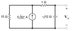
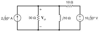
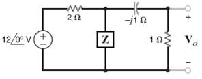
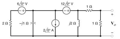
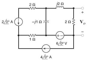
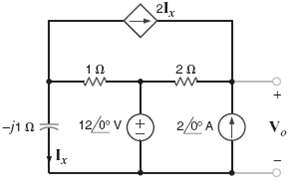
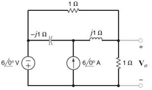
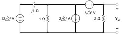
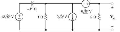
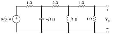
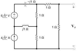
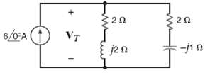
Find the frequency-domain voltage Vo, as shown infigure.
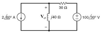
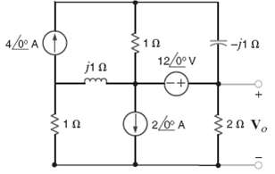
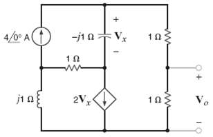
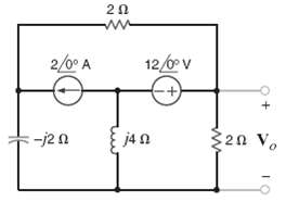
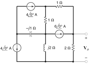
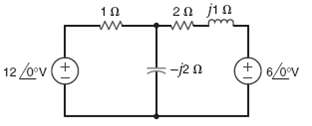
Find vo, in the network infigure.
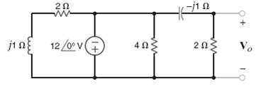
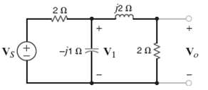
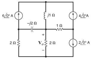
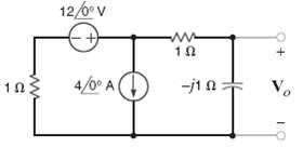
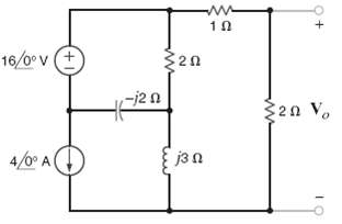
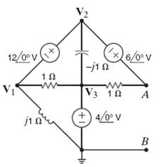
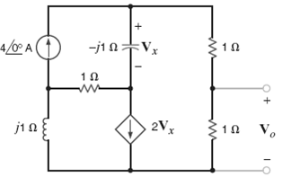
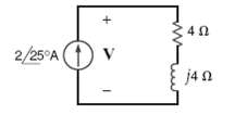
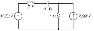
Find Vo in the network infigure.
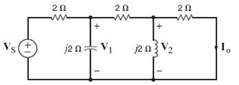
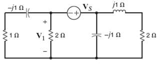
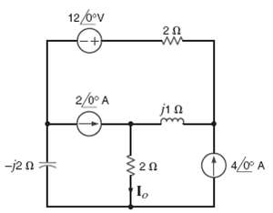
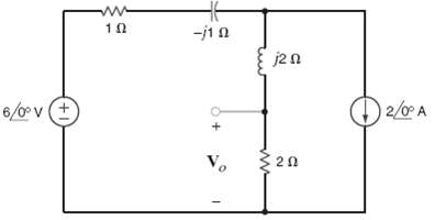
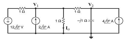
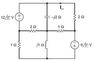
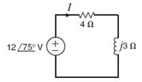
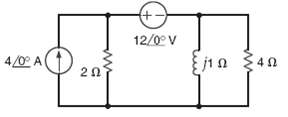
Determine Io in the network shown in figure. If Vs =12
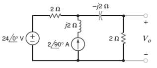
Given the network in figure determine the valve of Vo if Vs = 24
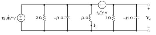
Find I1 and Vo in the network infigure.
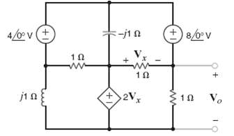
Find Vo in the network infigure.
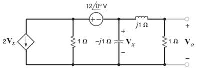
Find Vo in the circuit infigure.
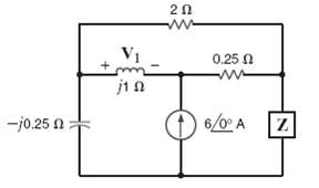
Find VS in the network in figure if V1 = 4
If V1 = 4
In the network in figure, V1 = 5
In the network in figure, Vo is known to be 4
In the network in figure Io = 4
If Io = 4
If Io = 4
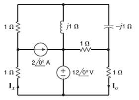
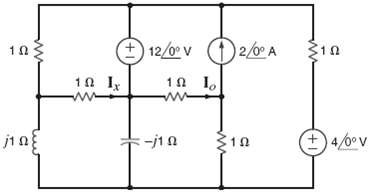
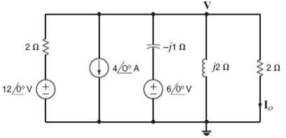
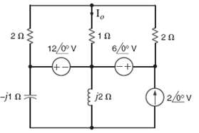
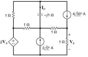
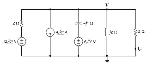
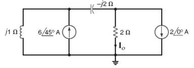
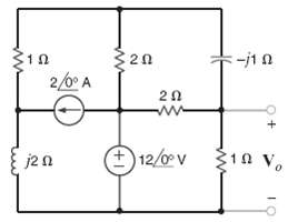
Using nodal analysis, find Io in the circuit infigure.
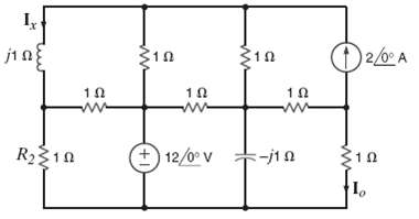
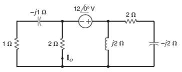
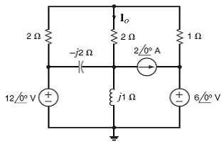
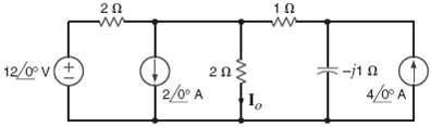
Using nodal analysis find Io in the circuit infigure.
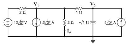
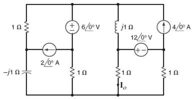
Use nodal analysis to find Io in the circuit infigure.
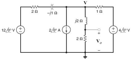
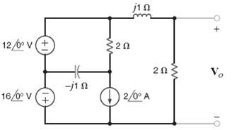
Find Vo in the network in figure using nodal analysis.
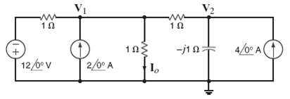
Use the super node technique to find Io in the circuit infigure.
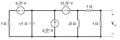
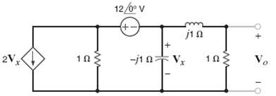
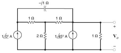
Use nodal analysis to find Vo in the circuit infigure.
Use nodal analysis to find Vo in the circuit infigure.
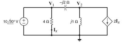
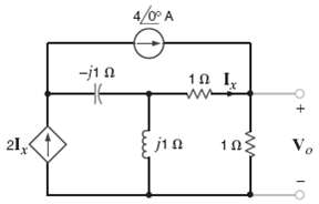
Find Io in the network in figure using nodal analysis.
Find Io in the circuit in figure using nodalanalysis.
Use nodal analysis to find Io in the circuit infigure.
Use nodal analysis to find Vo in the circuit infigure.
Find the voltage across the inductor in the circuit shown in 1 figure using nodalanalysis.
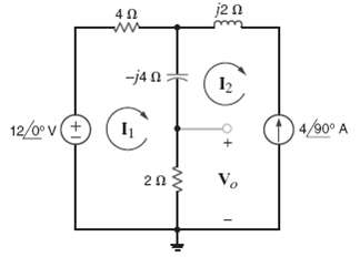
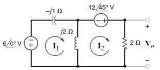
Use mesh analysis to find Vo in the circuit shown infigure.
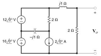
Use mesh analysis to find Vo in the circuit shown infigure.
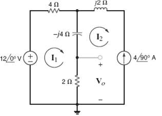
Using loop analysis and MATLAB, find Io in the network infigure.
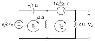
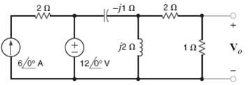
Find Vo in the circuit in figure using mesh analysis.
Use mesh analysis to find Vo in the circuit infigure.
Using loop analysis, determine Vo in the network infigure.
Use loop analysis to find Io in the network infigure.
Determine Vo in the circuit infigure.
Find Vo in the network infigure.
Find Vo in the network infigure.
Find Vo in the network infigure.
Find Vo in the circuit infigure.
Find Vo in the network infigure.
Use superposition to find Vo in the network infigure.
Using superposition, find Vo in the circuit infigure.
Use both superposition and MATLAB to determine Vo in the circuit infigure.
Find Vo in the network in figure using superposition.
Find Vo in the network in figure using superposition.
Use source transformation to determine Io in the network infigure.
Use source exchange to determine Vo in the network infigure.
Use source transformation to determine Io in the network infigure.
Use source exchange to find the current Io in the network infigure.
Use source transformation to determine Vo in the network infigure.
Use Thevenin?s theorem to find Vo in the network in figure.
Find Vo in figure using Thevenin?s theorem.
Use Thevenin?s theorem to find Vo in the circuit in figure.
Find Vo in figure using Thevenin?s theorem.
Apply Thevenin?s theorem twice to find Vo?in the circuit in figure.
Use Thevenin?s theorem to find Vo in the network in figure.
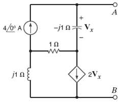
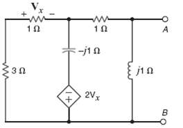
Given the network in figure, find the Thevenin?s equivalent of the network at terminals A-B?
Find Vo in the network in figure using Thevenin?s theorem.
Find the Thevenin?s equivalent for the network in figure at terminals A-B.
Find the current in the inductor in the circuit shown in figure using Norton?s theorem.
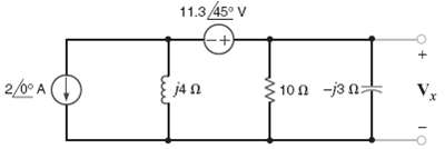
Find Vx in the circuit in figure using Norton's theorem.
Find Io in the network in figure using Norton's theorem.
Use Norton's theorem to find Vo in the network infigure.
Find Vo using Norton's theorem for the circuit in figure.
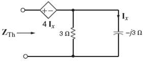
Calculate the Thevenin equivalent impedance ZTh in the circuit shown in figure.
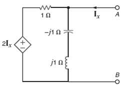
Find the Thevenin's equivalent for the network in figure at terminals A-B.
Find the Thevenin's equivalent of the network in figure at terminals A-B.
Apply both Norton's theorem and MATLAB to find Bo in the network in figure.
Use MATLAB to find the node voltages in the network in figure.
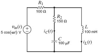
Using the PSPICE schematics editor, draw the circuit in figure. At what frequency are the magnitudes of iC (t) and iL (t) equal?
The network in figure operates at f = 400 Hz. Use PSPICE to find the current Io.
The network in figure operates at f = 60Hz. Use PSPICE to find the voltage vo.
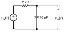
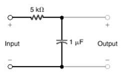
Given the low-pass filter shown in figure, find the half-power frequency of this circuit, if the source frequency is 8Hz. (a) 8 Hz (b) 2 Hz (c) 12 Hz (d) 4Hz
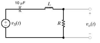
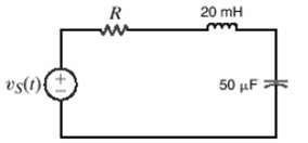
Given the band-pass filter shown in figure, find the value of R necessary to provide a resonant frequency of 1000 rad/s and a BW of 100 rad/s (a) 2 ? (b) 10 ? (c) 6 ? (d) 5 ?
Given the low-pass filter circuit shown in figure, find the frequency in Hz at which the output is down 3dB from the dc, or very low frequency, output. (a) 26 Hz (b) 60 Hz (c) 47 Hz (d) 32Hz
Given the series circuit in figure, find the value of R so that the BW of the network about the resonant frequency is 200rad/s. (a) 8 ? (b) 2 ? (c) 4 ? (d) 6 ?
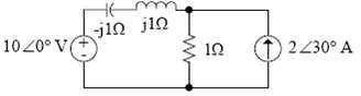
Determine the average power supplied by each source in the circuit infigure.
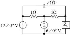
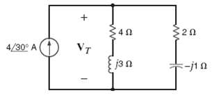
Given the circuit in figure, determine the impedance ZL for maximum average power transfer and the value of the maximum average power transferred to this load.
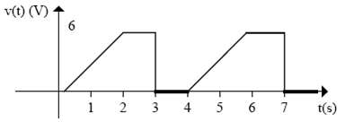
Calculate the rms value of the waveform shown in figure.
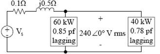
Determine the source voltage in the network shown infigure.
A plant consumes 75 kW at a power factor of 0.70 lagging from a 240-V rms 60 Hz line. Determine the value of the capacitor that when placed in parallel with the load will change the load power factor to 0.9 lagging.
Determine the equation for the voltage and the instantaneous power in the network infigure.
Determine the equations for the current and the instantaneous power in the network infigure.
The voltage and current at the input of a network are given by the expressions v(t) = 6 cost wt V, i(t) = 4 sin wt A. Determine the average power absorbed by the network.
The voltage and current at the input of a circuit are given by the expressions v(t) = 170 cos (wt + 30o)V, i(t) = 5 cos (wt + 45o)A. determine the average power absorbed by the circuit.
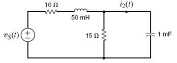
Given vs(t) = 100 cos 100t volts, find the average power supplied by the source and the current i2(t) in the network infigure.
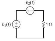
Find the average power absorbed by the resistor in the circuit shown in figure if v1 (t) = 10cos (377t + 60o) V and v2 (t) = 20cos (377t + 120o) V.
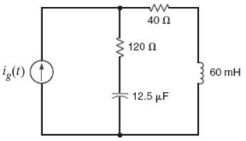
If ig(t) = 0.5 cos 2000t A, find the average power absorbed by each element in the circuit infigure.
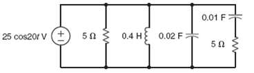
Calculate the power absorbed by each element in the circuit in figure.
Given the network in figure, find the power supplied and the average power absorbed by eachelement.
Given the network in figure, determine which elements are supplying power, which ones is absorbing power, and how much power is being supplied and absorbed.
Determine the average power supplied by each source in the network shown infigure.
Given the circuit in figure, determine the amount of average power supplied to the network.
Determine the average power absorbed by the 4-? resistor in the network shown in figure.
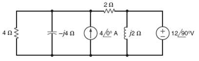
Compute the average absorbed by each of the elements to the right of the dashed line in the circuit shown infigure.
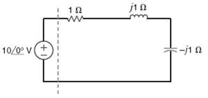
Find the average power absorbed by the network shown infigure.
Given the network in figure, find the power supplied and the average power absorbed by each element.
Determine the average power supplied by each source in the network shown infigure.
Given the network in figure, shown that the power supplied by the sources is equal to the power absorbed by the passiveelements.
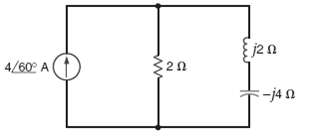
Calculate the average power absorbed by the 1-? resistor in the network shown in figure.
Showing 2300 - 2400
of 3459
First
17
18
19
20
21
22
23
24
25
26
27
28
29
30
31
Last
Step by Step Answers