New Semester
Started
Get
50% OFF
Study Help!
--h --m --s
Claim Now
Question Answers
Textbooks
Find textbooks, questions and answers
Oops, something went wrong!
Change your search query and then try again
S
Books
FREE
Study Help
Expert Questions
Accounting
General Management
Mathematics
Finance
Organizational Behaviour
Law
Physics
Operating System
Management Leadership
Sociology
Programming
Marketing
Database
Computer Network
Economics
Textbooks Solutions
Accounting
Managerial Accounting
Management Leadership
Cost Accounting
Statistics
Business Law
Corporate Finance
Finance
Economics
Auditing
Tutors
Online Tutors
Find a Tutor
Hire a Tutor
Become a Tutor
AI Tutor
AI Study Planner
NEW
Sell Books
Search
Search
Sign In
Register
study help
engineering
electrical engineering
Basic Engineering Circuit Analysis 9th Edition J. David Irwin - Solutions
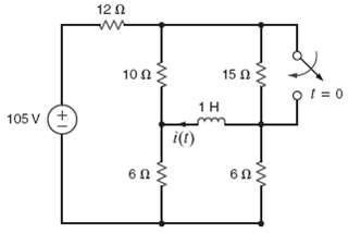
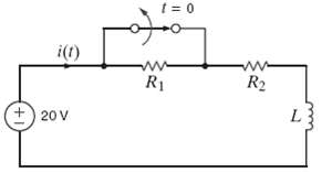
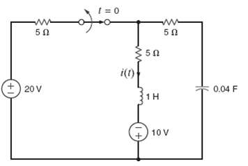
Find i(t) for t > 0 in the circuit of figure using the step-by-step method.
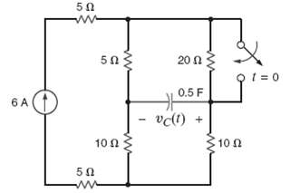
Find vc(t) for t > 0 in the circuit of figure using the step-by-step method.
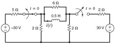
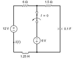
Find i(t) for t > 0 in the circuit of figure using the step-by-step method.
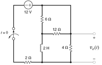
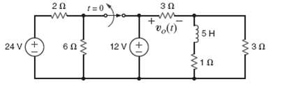
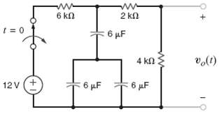
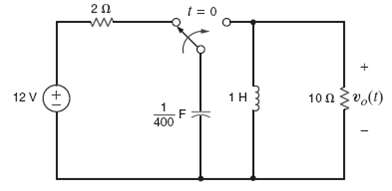
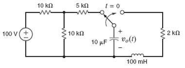
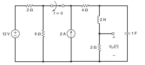
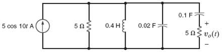
Use the step-by-step technique to find vo(t) for t > 0 in the circuit in figure.
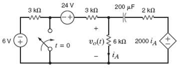
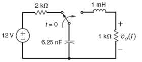
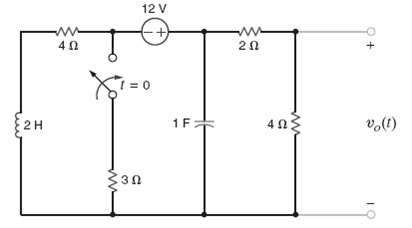
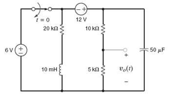
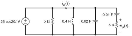
Find vo(t) for t > 0 in the circuit in figure using the step-by-step method.
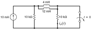
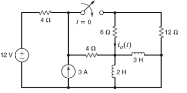
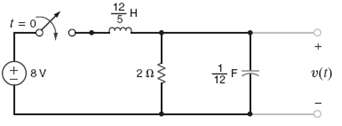
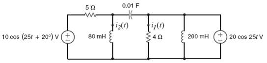
Use the step-by-step method to find io(t) for t > 0 in the circuit in figure.
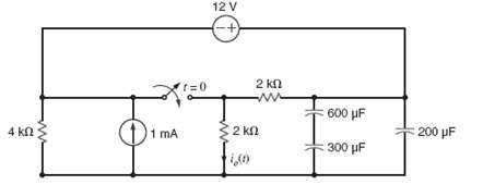
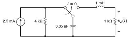
Use the step-by-step technique to find io(t) for t > 0 in network in figure.
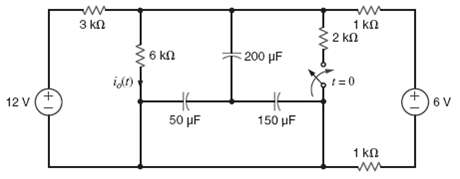
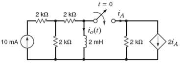
Find io(t) for t > 0 in the circuit in figure using the step by step technique.
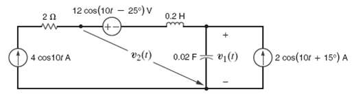
Use the step-by-step method to find vo(t) for t > 0 in the network in figure.
Use the step-by-step method to find io(t) for t > 0 in the network in figure.
Find io(t) for t > 0 in the network in figure using the step-by-step method.
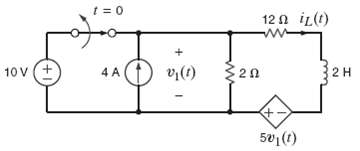
Find iL(t) for t > 0 in the circuit of using the step-by-step method.
Use the step-by-step technique to find vo(t) for t > 0 in the network in figure.
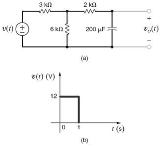
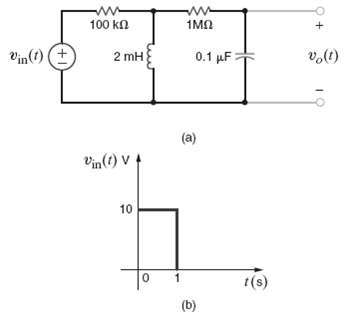
Determine the equation for the voltage vo(t) for t > 0 figure when subjected to the input pulse shown in figure.
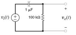
Find the output voltage vo(t) in the network in figure if the input voltage is vi(t) = 5(u(t) ? u (t ? 0.05)V.
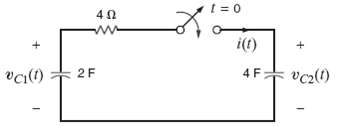
Given that vc1 (0?) = ? 10V and vc2 (0?) = 20 V in the circuit in figure find i(0+)
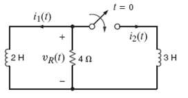
The switch in the circuit in figure is closed at t = 0. If i1(0?) = 2 A, determine i2(0+), vR(0+), and i1(t = ?).
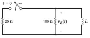
In the circuit in figure vR(t) = 100e ? 400t V for t R(t) for t > 0.
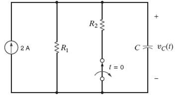
The switch in the circuit in figure has been closed for a long time and is opened at t = 0. If vc(t) = 20 ? 8e?0.05tV, find R1, R2, and C.
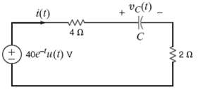
Given that i(t) = 13.33e ? t ? 8.33e ? 0.5t A for t > 0 in the network in figure, find the following. (a) vc (0),? (b) vc (t = 1s), and? (c) The capacitance C.
Given that i(t) = 2.5 + 1.5e ?4t A for t > 0 in the circuit in figure, find R1, R2, and L.
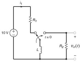
For the circuit in figure, choose R1, R2, and L such that vo(t) = ? 20e? kft V and the current i1 never exceeds 1 A.
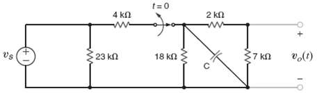
For the network in figure, choose C so the time constant will be 120?s for t > 0.
The differential equation that describes the current io(t) in a network is find? (a) The characteristic equation of the network, (b) The network?s natural frequencies, and (c) The expression for io(t).
The terminal current in a network is described by the equation. (a) The characteristic equation of the network, (b) The network?s natural frequencies, and (c) The expression for io(t).
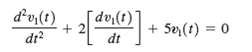
The voltage v1(t) in a network is defined by the equation. (a) The characteristic equation of the network, (b) The network?s natural frequencies, and (c) The expression for v1?(t).
The output voltage of a circuit is described by the differential equation. (a) The characteristic equation of the network, (b) The network?s natural frequencies, and (c) The expression for vo(t).
The voltage v1 (t) in a network is defined by the equation, find (a) The characteristic equation of the network. (b) The circuit?s natural frequencies. (c) The expression for v1 (t).
The parameters for a parallel RLC circuit are R = 1Ω, L = ½ H, and C = 1/2F. Determine the type of damping exhibited by the circuit.
A series RLC circuit contains a resistor of R = 2 Ω and a capacitor C = 1/2F. Select the value of the inductor so that the circuit critically damped.
A parallel RLC circuit contains a resistor R = 1Ω and an inductor L = 2H. Select the value of the capacitor so that the circuit is critically damped.
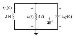
For the under damped circuit shown in figure, determine the voltage v(t) if the initial conditions on the storage elements are iL(0) = 1 A and vc(0) =10V.
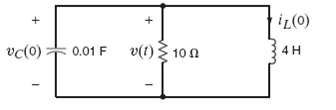
In the critically damped circuit shown in figure, the initial condition on the storage elements are iL(0) = 2.A and vC(0) = 5 V. Determine the voltagev(t).
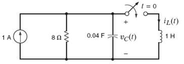
Find vC(t) for t > 0 in the circuit in figure.
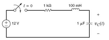
Find vc(t) for t > 0 in the circuit in figure if vc(0) =0.
Find vo(t) for t > 0 in the circuit in figure and plot and response including the time interval just prior to closing the switch.
Find vo(t) for t > 0 in the circuit in figure and plot the response including the time interval just prior to moving theswitch.
In the circuit shown in figure find v(t) > 0.
Find vo(t) for t > 0 in the circuit in figure and plot the response including the time interval just prior to moving theswitch.
Find vo(t) for t > 0 in the network in figure and plot the response including the time interval just prior to moving theswitch.
The switch in the circuit in figure has been closed for a long time and is opened at t = 0. Find i(t) for t > 0.
The switch in the circuit in figure has been closed for a long time and is opened at t = 0. Find i(t) for t > 0.
Design a parallel RLC circuit with R ≥ 1kΩ that has the characteristic equation s2 + 4 x 10⁷s + 4 x 1014 = 0.
Design a parallel RLC circuit with R ≥ 1kΩ that has the characteristic equation s2 + 4 x 10⁷s + 4 x 1014 = 0. Discuss.
For the network shown in figure use PSPICE to plot vo(t) over a 10-sec interval starting at t = 0 using a 100-ms step size.
Given the network in figure, use PSPICE to plot vo(t) over a 10-s interval starting at t = 0 using a 100-ms step size.
Given the network in figure, use PSPICE to plot vo(t) over a 10-s interval starting at t = 0 using a 100-ms step size.
Given the network in figure and the input voltage shown in figure, use PSPICE to plot the voltage vo(t) over the interval 0 ? t ? 4 s using a 20-ms step size.
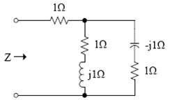
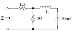
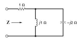
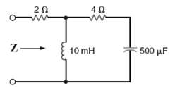
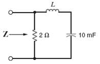
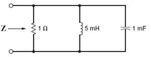
Find the frequency domain impedance Z, shown in figure.
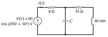
If the impedance of the network in figure is real at f = 60Hz, what is the value of the inductor L?
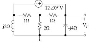
Use nodal analysis to find V0 in the network in figure.
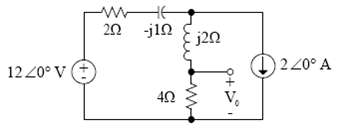
Find V0 in the network in figure using? (a) Loop analysis? (b) Superposition and? (c) Thevenin?s Theorem.
Given i(t) = 5 cos (400t – 120o) A, determine the period of the current and the frequency in Hertz.
Determine the relative phase relationship of the two waves.
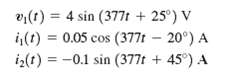
Given the following voltage and current determine the phase relationship between i(t) and v(t).
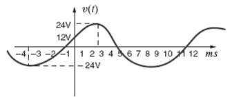
Write the expression for the waveform shown in figure as a cosine function with numerical values for the amplitude, frequency, and phase.
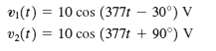
Determine the phase angles by which v1 (t) leads i1 (t) and v1 (t) leads i2 (t), where
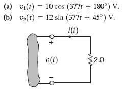
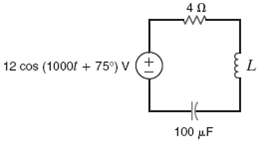
Calculate the current in the resistor in figure if the voltage input is given the answers in both the time and frequency domains.
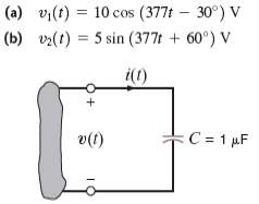
Calculate the current in the capacitor shown in figure if the voltage input is given the answers in both the time and frequency domains.
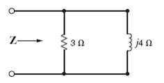
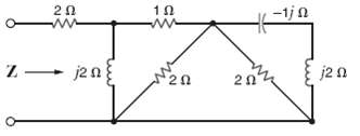
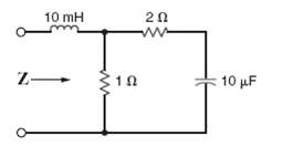
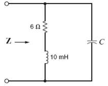
Find the frequency-domain impedance, Z, in the network in figure.
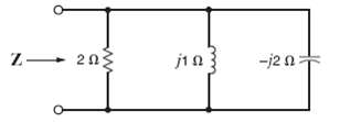
Find the frequency-domain impedance, Z, as shown in figure.
Find the frequency-domain impedance, Z, as shown infigure.
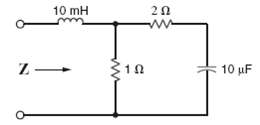
Find the impedance, Z, shown in figure at a frequency of60Hz.
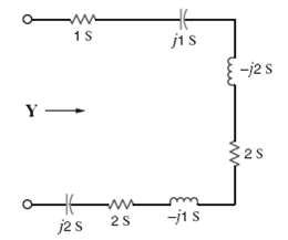
Find Y in the network infigure. ????"/>
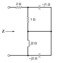
Find the frequency-domain impedance, Z, shown infigure.
Find the frequency-domain impedance, Z, shown infigure.
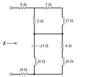
Find Z in the network infigure.
Find the impedance, Z, shown in figure at a frequency of 60Hz.
Find the impedance, Z, shown in figure at a frequency of 400Hz.
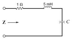
Find the value of C in the circuit shown in figure so that Z is purely resistive at the frequency of 60Hz.
In the circuit shown in figure, determine the value of the inductance such that the current is in phase with the source voltage.
The impedance of the circuit in figure is real at f = 60 Hz. What is the value of L?
Find the value of the capacitance, C, shown in the circuit in figure so that i(t) will be in phase with the sourcevoltage.
The impedance of the network in figure is found to be purely real at f = 400 Hz. What is the value ofC?
Two elements (R, L, C) connected in parallel as shown in figure have an impedance of Z = 20 + 10? at w = 500 rad/s. Determine the elements and their values.
Find the frequency at which the circuit shown in figure purelyresistive.
The impedance of the box in figure is 5 + j4? at 1000 rad/s. What is the impedance at 1300 rad/s?
The admittance of the box in figure in 0.1 + j0.2S at 500 rad/s, what is the impedance at 300rad/s
Find vs(t) in the circuit infigure.
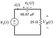
Draw the frequency-domain network and calculate i(t) in the circuit shown in figure if vs(t) is 15 sin (10000t). V. Also, using a phasor diagram, shown that vC(t) + vR(t) =vx(t).
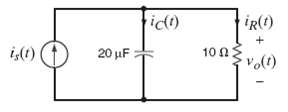
Draw the frequency-domain network and calculate vo(t) in the circuit shown in figure if is(t) is 1 cos (2500t ? 45o) A. Also, using a phasor diagram, show that iC(t) + iR(t) = is(t).
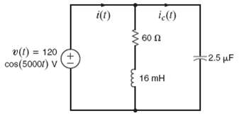
Find iC(t) and i(t) in the network infigure.
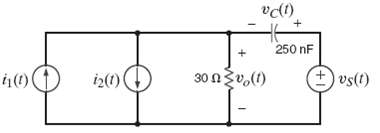
Draw the frequency-domain network and calculate vo(t) in the circuit shown in figure if i1 (t) is 200 cos (105t + 60o) mA, i2(t) is 100 sin (105t + 90o)mA, and vS(t) = 10 sin (105t) V. Also, use a phasor diagram to determinevC(t).
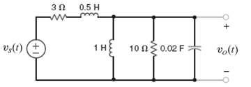
If vs(t) = 20 cos 5t volts, find v0(t) in the network infigure.
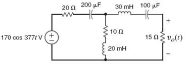
Find v0(t) in the circuit infigure.
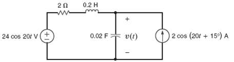
Find v(t) in the network infigure.
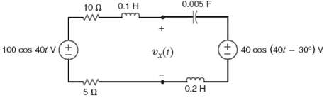
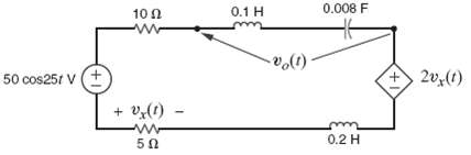
Find vx(t) in the circuit infigure.
Find vo(t) in the network infigure.
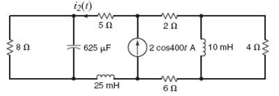
Find i(t) and i2(t) in the circuit infigure.
Find vo(t) and io(t) in the network infigure.
Find v1 (t) and v2 (t) in the circuit infigure
Find vo(t) in the network infigure.
Find i2(t) in the circuit infigure.
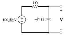
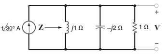
Find the voltage V shown infigure.
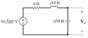
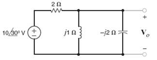
Find the voltage Vo as shown infigure.
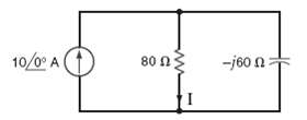
Find the frequency-domain current I, as shown infigure.
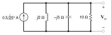
Find the frequency-domain voltage Vo, as shown infigure.
Find the voltage V shown infigure.
Find the voltage Vo, shown infigure.
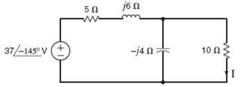
Find the frequency-domain current I, as shown infigure.
Showing 2200 - 2300
of 3459
First
16
17
18
19
20
21
22
23
24
25
26
27
28
29
30
Last
Step by Step Answers