New Semester
Started
Get
50% OFF
Study Help!
--h --m --s
Claim Now
Question Answers
Textbooks
Find textbooks, questions and answers
Oops, something went wrong!
Change your search query and then try again
S
Books
FREE
Study Help
Expert Questions
Accounting
General Management
Mathematics
Finance
Organizational Behaviour
Law
Physics
Operating System
Management Leadership
Sociology
Programming
Marketing
Database
Computer Network
Economics
Textbooks Solutions
Accounting
Managerial Accounting
Management Leadership
Cost Accounting
Statistics
Business Law
Corporate Finance
Finance
Economics
Auditing
Tutors
Online Tutors
Find a Tutor
Hire a Tutor
Become a Tutor
AI Tutor
AI Study Planner
NEW
Sell Books
Search
Search
Sign In
Register
study help
engineering
electrical engineering
Electric Machinery 6th Edition Charles Kingsley, Jr, Stephen D. Umans - Solutions
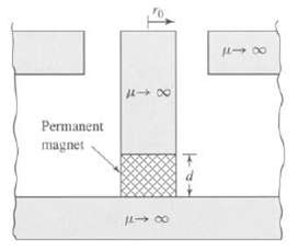
Winding 1 in the loudspeaker of Problem 3.25 (Figure) is replaced by a permanent magnet as shown in Figure. The magnet can be represented by the linear characteristic Bm = ?R (Hm ? Hc). a. Assuming the voice coil current to be zero, (i2 = 0), calculate the magnetic flux density in the air gap. b.
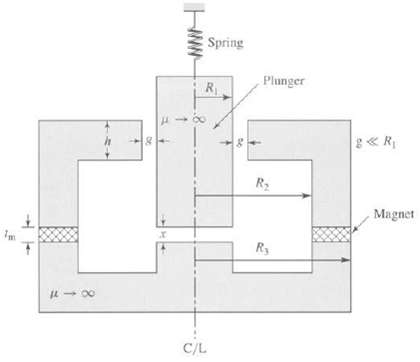
Figure shows a circularly symmetric system in which a moveable plunger (constrained to move only in the vertical direction) is supported by a spring of spring constant K = 5.28 N/m. The system is excited by a samarium-cobalt permanent-magnet in the shape of a washer of outer radius R3, inner radius
The plunger of a solenoid is connected to a spring. The spring force is given by f = K0 (0.9a – x), where x is the air-gap length. The inductance of the solenoid is of the form L = L0 (1 – x/a), and its winding resistance is R. The plunger is initially stationary at position x = 0.9a when a dc
Consider the solenoid system of Problem 3.30. Assume the following parameter values: L0 = 4.0mH a = 2.2cm R = 1.5Ω K0 = 3.5N/cm. The plunger has mass M = 0.2 kg. Assume the coil to be connected to a dc source of magnitude 4 A. Neglect any effects of gravity.a. Find the equilibrium displacement
The solenoid of Problem 3.31 is now connected to a dc voltage source of magnitude 6 V.a. Find the equilibrium displacement X0.b. Write the dynamic equations of motion for the system.c. Linearize these dynamic equations for incremental motion of the system around its equilibrium position.
Consider the single-coil rotor of Example 3.1. Assume the rotor winding to be carrying a constant current of I = 8 A and the rotor to have a moment of inertia J = 0.0125 kg ∙ m2.a. Find the equilibrium position of the rotor. Is it stable?b. Write the dynamic equations for the system.c. Find the
Consider a solenoid magnet similar to that of Example 3.10 (Figure) except that the length of the cylindrical plunger is reduced to a + h. Derive the dynamic equations of motion of the system.
The nameplate on a 460-V, 50-hp, 60-Hz, four-pole induction motor indicates that its speed at rated load is 1755 r/min. Assume the motor to be operating at rated load.a. What is the slip of the rotor?b. What is the frequency of the rotor currents?c. What is the angular velocity of the
Stray leakage fields will induce rotor-frequency voltages in a pickup coil mounted along the shaft of an induction motor. Measurement of the frequency of these induced voltages can be used to determine the rotor speed.a. What is the rotor speed in r/min of a 50-Hz, six-pole induction motor if the
A three-phase induction motor runs at almost 1198 r/min at no load and 1112 r/min at full load when supplied from a 60-Hz, three-phase source.a. How many poles does this motor have?b. What is the slip in percent at full load?c. What is the corresponding frequency of the rotor currents?d. What is
Linear induction motors have been proposed for a variety of applications including high-speed ground transportation. A linear motor based on the induction-motor principle consists of a car riding on a track. The track is a developed squirrel-cage winding, and the car, which is 4.5 m long and 1.25 m
A three-phase, variable-speed induction motor is operated from a variable frequency, variable-voltage source which is controlled to maintain constant peak air-gap flux density as the frequency of the applied voltage is varied. The motor is to be operated at constant slip frequency while the motor
Describe the effect on the torque-speed characteristic of an induction motor produced by(a) Halving the applied voltage and(b) Halving both the applied voltage and the frequency. Sketch the resultant torque-speed curves relative to that of rated-voltage and rated-frequency. Neglect the effects of
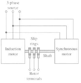
Figure shows a system consisting of a three-phase wound-rotor induction machine whose shaft is rigidly coupled to the shaft of a three-phase synchronous motor. The terminals of the three-phase rotor winding of the induction machine are brought out to slip rings as shown. With the system supplied
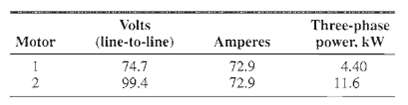
A system such at that shown in Figure is used to convert balanced 50-Hz voltages to other frequencies. The synchronous motor has four poles and drives the interconnected shaft in the clockwise direction. The induction machine has six poles and its stator windings are connected to the source in such
A three-phase, eight-pole, 60-Hz, 4160-V, 1000-kW squirrel-cage induction motor has the following equivalent-circuit parameters in ohms per phase Y referred to the stator: R1 = 0.220 R2 = 0.207 X1 = 1.95 X2 = 2.42 Xm = 45.7. Determine the changes in these constants which will result from the
A three-phase, Y-connected, 460-V (line-line), 25-kW, 60-Hz, four-pole induction motor has the following equivalent-circuit parameters in ohms per phase referred to the stator: R1 = 0.103 R2 = 0.225 X1 = 1.10 X2 = 1.13 Xm = 59.4. The total friction and wind age losses may be assumed constant at 265
Consider the induction motor of Problem 6.10.a. Find the motor speed in r/min corresponding to the rated shaft output power of 25 kW.b. Similarly, find the speed in r/min at which the motor will operate with no external shaft load (assuming the motor load at that speed to consist only of the
A 15-kW, 230-V, three-phase, Y-connected, 60-Hz, four-pole squirrel-cage induction motor develops full-load internal torque at a slip of 3.5 percent when operated at rated voltage and frequency. For the purposes of this problem, rotational and core losses can be neglected. The following motor
The induction motor of Problem 6.13 is supplied from a 230-V source through a feeder of impedance Zf = 0.05 + j0.14 ohms. Find the motor slip and terminal voltage when it is supplying rated load.
A three-phase induction motor, operating at rated voltage and frequency, has a starting torque of 135 percent and a maximum torque of 220 percent, both with respect to its rated-load torque. Neglecting the effects of stator resistance and rotational losses and assuming constant rotor resistance,
When operated at rated voltage and frequency, a three-phase squirrel-cage induction motor (of the design classification known as a high-slip motor) delivers full load at a slip of 8.7 percent and develops a maximum torque of 230 percent of full load at a slip of 55 percent. Neglect core and
A 500-kW, 2400-V, four-pole, 60-Hz induction machine has the following equivalent-circuit parameters in ohms per phase Y referred to the stator: R1 = 0.122 R2 = 0.317 X1 = 1.364 X2 = 1.32 Xm = 45.8. It achieves rated shaft output at a slip of 3.35 percent with an efficiency of 94.0 percent. The
Write a MATLAB script to plot the efficiency as a function of electric power output for the induction generator of Problem 6.17 as the slip varies from -0.5 to -3.2 percent. Assume the generator to be operating into the system with the feeder impedance of part (c) of Problem 6.17.
For a 25-kW, 230-V, three-phase, 60-Hz squirrel-cage motor operating at rated voltage and frequency, the rotor I2R loss at maximum torque is 9.0 times that at full-load torque, and the slip at full-load torque is 0.023. Stator resistance and rotational losses may be neglected and the rotor
A squirrel-cage induction motor runs at a full-load slip of 3.7 percent. The rotor current at starting is 6.0 times the rotor current at full load. The rotor resistance and inductance is independent of rotor frequency and rotational losses, stray-load losses and stator resistance may be
A A-connected, 25-kW, 230-V, three-phase, six-pole, and 50-Hz squirrel-cage induction motor has the following equivalent-circuit parameters in ohms per phase Y: R1 = 0.045 R2 = 0.054 X1 = 0.29 X2 = 0.28 Xm = 9.6a. Calculate the starting current and torque for this motor connected directly to a
The following data apply to a 125-kW, 2300-V, three-phase, four pole, 60-Hz squirrel-cage induction motor: Stator-resistance between phase terminals = 2.23 Ω. No-load test at rated frequency and voltage: Line current = 7.7 A Three-phase power = 2870 W. Blocked-rotor test at 15 Hz: Line voltage =
Two 50-kW, 440-V, three-phase, six-pole, 60-Hz squirrel-cage induction motors have identical stators. The dc resistance measured between any pair of stator terminals is 0.204 ft. Blocked-rotor tests at 60-Hz produce the following results. Determine the ratio of the internal starting torque
A 230-V, three-phase, six-pole, 60-Hz squirrel-cage induction motor develops a maximum internal torque of 288 percent at a slip of 15 percent when operated at rated voltage and frequency. If the effect of stator resistance is neglected, determine the maximum internal torque that this motor would
A 75-kW, 50-Hz, four-pole, and 460-V three-phase, wound-rotor induction motor develops full load torque at 1438 r/min with the rotor short-circuited. An external non-inductive resistance of 1.1Ω is placed in series with each phase of the rotor, and the motor is observed to develop its rated torque
A 75-kW, 460-V, three-phase, four-pole, 60-Hz, wound-rotor induction motor develops a maximum internal torque of 225 percent at a slip of 16 percent when operated at rated voltage and frequency with its rotor short-circuited directly at the slip rings. Stator resistance and rotational losses may be
Neglecting any effects of rotational and core losses, use MATLAB to plot the internal torque versus speed curve for the induction motor of Problem 6.10 for rated-voltage, rated-frequency operation. On the same plot, plot curves of internal torque versus speed for this motor assuming the rotor
A 100-kW, three-phase, 60-Hz, 460-V, six-pole wound-rotor induction motor develops its rated full-load output at a speed of 1158 r/min when operated at rated voltage and frequency with its slip rings short-circuited. The maximum torque it can develop at rated voltage and frequency is 310 percent of
A 460-V, three-phase, six-pole, 60-Hz, 150-kW, wound-rotor induction motor develops an internal torque of 190 percent with a line current of 200 percent (torque and current expressed as a percentage of their full-load values) at a slip of 5.6 percent when running at rated voltage and frequency with
The resistance measured between each pair of slip rings of a three-phase, 60-Hz, 250-kW, 16 poles, and wound-rotor induction motor is 49 mΩ. With the slip tings short-circuited, the full-load slip is 0.041. For the purposes of this problem, it may be assumed that the slip-torque curve is a
Consider a separately-excited dc motor. Describe the speed variation of the motor operating unloaded under the following conditions:a. The armature terminal voltage is varied while the field current is held constant.b. The field current is varied while the armature terminal voltage is held
A dc shunt motor operating at an armature terminal voltage of 125 V is observed to be operating at a speed of 1180 r/min. When the motor is operated unloaded at the same armature terminal voltage but with an additional resistance of 5 Ω in series with the shunt field, the motor speed is observed
For each of the following changes in operating condition for a dc shunt motor, describe how the armature current and speed will vary:a. Halving the armature terminal voltage while the field fluxes and load torque remain constant.b. Halving the armature terminal voltage while the field current and
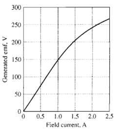
The constant-speed magnetization curve for a 25-kW, 250-V dc machine at a speed of 1200 r/min is shown in Figure. This machine is separately excited and has an armature resistance of 0.14?. This machine is to be operated as a dc generator while driven from a synchronous motor at constant speed. a.
The dc generator of Problem 7.4 is to be operated at a constant speed of 1200 r/min into a load resistance of 2.5?. a. Using the "spline ( )" function of MATLAB and the points of the magnetization curve of Figure at 0, 0.5, 1.0, 1.5, 2.0, and 2.5 A, create a MATLAB plot of the magnetization curve
The dc machine of Problem 7.4 is to be operated as a motor supplied by a constant armature terminal voltage of 250 V. If saturation effects are ignored, the magnetization curve of Figure becomes a straight line with a constant slope of 150 volts per ampere of field current. For the purposes of this
Repeat Problem 7.6 including the saturation effects represented by the saturation curve of Figure. For part (a), set the field current equal to the value required to produce an open-circuit armature terminal voltage of 250 V at 1200r/min.
A 15-kW, 250-V, 1150 r/min shunt generator is driven by a prime mover whose speed is 1195 r/min when the generator delivers no load. The speed falls to 1140 r/min when the generator delivers 15 kW and may be assumed to decrease in proportion to the generator output. The generator is to be changed
When operated from a 230-V dc supply, a dc series motor operates at 975 r/min with a line current of 90 A. Its armature-circuit resistance is 0.11Ω and its series-field resistance is 0.08Ω. Due to saturation effects, the flux produced by an armature current of 30 A is 48 percent of that at an
Consider the long-shunt, 250-V, 100-kW dc machine of Example 7.3. Assuming the machine is operated as a motor at a constant supply voltage of 250-V with a constant shunt-field current of 5.0 A, use MATLAB to plot the motor speed as a function of load. Use the MATLAB "spline ( )" function to
A 250-V dc shunt-wound motor is used as an adjustable-speed drive over the range from 0 to 2000 r/min. Speeds from 0 to 1200 r/min are obtained by adjusting the armature terminal voltage from 0 to 250 V with the field current kept constant. Speeds from 1200 r/min to 2000 r/min are obtained by
Two adjustable-speed dc shunt motors have maximum speeds of 1800r/min and minimum speeds of 500r/min. Speed adjustment is obtained by field-rheostat control. Motor A drives a load requiring constant power over the speed range; motor B drives one requiring constant torque. All losses and armature
Consider a dc shunt motor connected to a constant-voltage source and driving a load requiring constant electromagnetic torque. Show that if Ea > 0.5Vt (the normal situation), increasing the resultant air-gap flux decreases the speed, whereas if Ea < 0.5Vt (as might be brought about by
A separately-excited dc motor is mechanically coupled to a three-phase, four-pole, 30-kVA, 460-V, cylindrical-pole synchronous generator. The dc motor is connected to a constant 230-V dc supply, and the ac generator is connected to a 460-V, fixed-voltage, fixed-frequency, three-phase supply. The
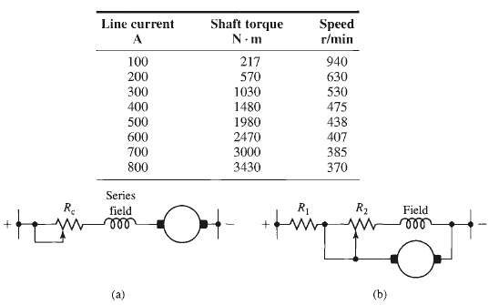
A 150-kW, 600-V, 600 r/min dc series-wound railway motor has a combined field and armature resistance (including brushes) of 0.125?. The full-load current at rated voltage and speed is 250 A. The magnetization curve at 400r/min is as follows. Determine the internal starting torque when the starting
A 25-kW, 230-V shunt motor has an armature resistance of 0.11Ω and a field resistance of 117Ω. At no load and rated voltage, the speed is 2150 r/min and the armature current is 6.35 A. At full load and rated voltage, the armature current is 115 A and, because of armature reaction, the flux is 6
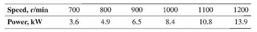
A 91-cm axial-flow fan is to deliver air at 16.1m3/sec against a static pressure of 120 Pa when rotating at a speed of 1165 r/min. The fan has the following speed-load characteristic. It is proposed to drive the fan by a 12.5 kW, 230-V, 46.9-A, four-pole dc shunt motor. The motor has an armature
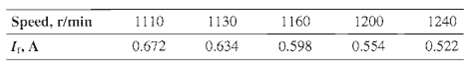
A shunt motor operating from a 230-V line draws a full-load armature current of 46.5 A and runs at a speed of 1300 r/min at both no load and full load. The following data is available on this motor: Armature-circuit resistance (including brushes) = 0.17? Shunt-field turns per pole ? 1500 turns The
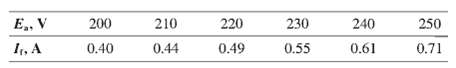
A 7.5-kW, 230-V shunt motor has 2000 shunt-field turns per pole, an armature resistance (including brushes) of 0.21?, and a commutating-field resistance of 0.035?. The shunt-field resistance (exclusive of rheostat) is 310?. When the motor is operated at no load with rated terminal voltage and
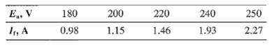
When operated at rated voltage, a 230-V shunt motor runs at 1750 r/min at full load and at no load. The full-load armature current is 70.8 A. The shunt field winding has 2000 turns per pole. The resistance of the armature circuit (including brushes and Interpoles) is 0.15?. The magnetization curve
A 230-V dc shunt motor has an armature-circuit resistance of 0.23Ω. When operating from a 230-V supply and driving a constant-torque load, the motor is observed to be drawing an armature current of 60 A. An external resistance of 1.0Ω is now inserted in series with the armature while the shunt
A common industrial application of dc series motors is in crane and hoist drives. This problem relates to the computation of selected motor performance characteristics for such a drive. The specific motor concerned is a series-wound, 230-V, totally-enclosed motor having a 1/2-hour crane rating of
A 25-kW, 230-V shunt motor has an armature resistance of 0.064Ω and a field-circuit resistance of 95Ω. The motor delivers rated output power at rated voltage when its armature current is 122 A. When the motor is operating at rated voltage, the speed is observed to be 1150 r/min when the machine
The manufacturer's data sheet for a permanent-magnet dc motor indicates that it has a torque constant Km = 0.21 V/(rad/sec) and an armature resistance of 1.9Ω. For a constant applied armature voltage of 85 V dc, calculatea. The no-load speed of the motor in r/min andb. Its stall (zero-speed)
Measurements on a small permanent-magnet dc motor indicate that it has an armature resistance of 4.6Ω. With an applied armature voltage of 5 V, the motor is observed to achieve a no-load speed of 11,210r/min while drawing an armature current of 12.5 mA.a. Calculate the motor torque constant Km in
The dc motor of Problem 7.25 will be used to drive a load which requires a power of 0.75 W at a speed of 8750 r/min. Calculate the armature voltage which must be applied to achieve this operating condition.
Repeat Example 8.1 for a machine identical to that considered in the example except that the stator pole-face angle is β = 45°.
In the paragraph preceding Equation 8.1, the text states that "under the assumption of negligible iron reluctance the mutual inductances between the phases of the doubly-salient VRM of Figure b will be zero, with the exception of a small, essentially constant component associated with leakage
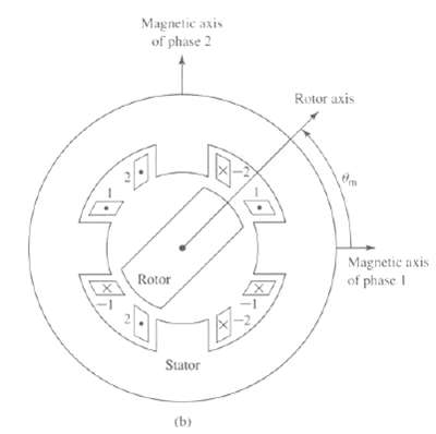
A 6/4 VRM of the form of Figure has the following properties: Stator pole angle ? = 30 ?, Rotor pole angle ? = 30 ?, Air-gap length g = 0.35 mm, Rotor outer radius R = 5.1 cm, Active length D = 7 cm. This machine is connected as a three-phase motor with opposite poles connected in series to form
In Section 8.2, when discussing Figure, the text states: "In addition to the fact that there are not positions of simultaneous alignment for the 6/4 VRM, it can be seen that there also are no rotor positions at which only a torque of a single sign (either positive or negative) can be produced."
Consider a three-phase 6/8 VRM. The stator phases are excited sequentially, requiting a total time of 15 msec. Find the angular velocity of the rotor in r/min.
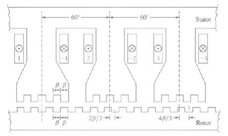
The phase windings of the castleated machine of Figure are to be excited by turning the phases on and off individually (i.e., only one phase can be on at any given time). a. Describe the sequence of phase excitations required to move the rotor to the fight (clockwise) by an angle of approximately
Replace the 28-tooth rotor of Problem 8.7 with a rotor with 26 teeth.a. Phase 1 is excited, and the rotor is allowed to come to rest. If the excitation on phase 1 is removed and excitation is applied to phase 2, calculate the resultant direction and magnitude (in degrees) of rotor rotation.b. The
Repeat Example 8.3 for a rotor speed of 4500 r/min.
Repeat Example 8.3 under the condition that the rotor speed is 4500 r/min and that a negative voltage of -250 V is used to turn off the phase current.
The three-phase 6/4 VRM of Problem 8.4 has a winding resistance of 0.15Ω/phase and a leakage inductance of 4.5 mH in each phase. Assume that the rotor is rotating at a constant angular velocity of 1750 r/min.a. Plot the phase-1 inductance as a function of the rotor angle θm.b. A voltage of 75 V
Assume that the VRM of Examples 8.1 and 8.3 is modified by replacing its rotor with a rotor with 75° pole-face angles as shown in Figure a. All other dimensions and parameters of the VRM are unchanged.a. Calculate and plot L (θm) for this machine.b. Repeat Example 8.3 except that the constant
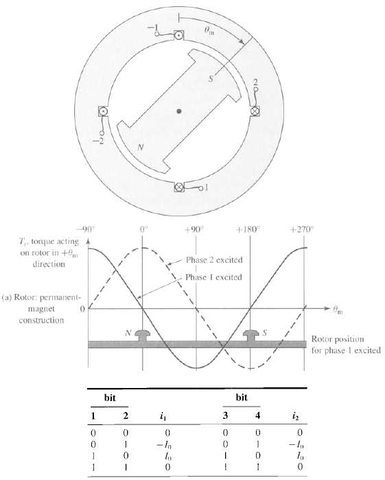
Consider a two-phase stepper motor with a permanent-magnet rotor such as shown in Figure and whose torque-angle curve is as shown in Figure a. This machine is to be excited by a four-bit digital sequence corresponding to the following winding excitation: a. Make a table of 4-bit patterns which will
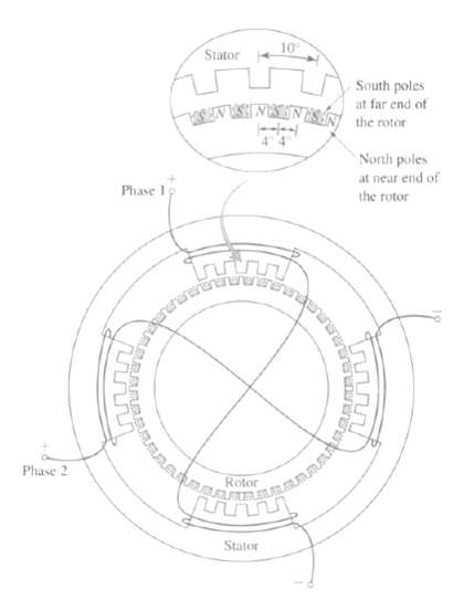
Figure shows a two-phase hybrid stepping motor with castleated poles on the stator. The rotor is shown in the position it occupies when current is flowing into the positive lead of phase 1. a. If phase one is turned off and phase 2 is excited with current flowing into its positive lead, calculate
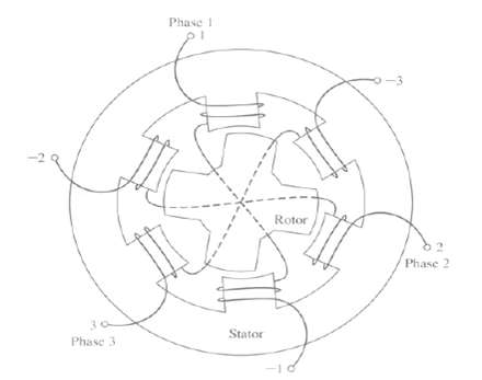
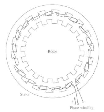
Consider a multi-stack, multiphase variable-reluctance stepping motor, such as that shown schematically in Figure, with 14 poles on each of the rotor and stator stacks and three stacks with one phase winding per stack. The motor is built such that the stator poles of each stack are aligned. a.
A 1-kW, 120-V, 60-Hz capacitor-start motor has the following parameters for the main and auxiliary windings (at starting): Zmain = 4.82 + j7.25Ω main winding, Zaux = 7.95 + j9.21Ω auxiliary windinga. Find the magnitude and the phase angles of the currents in the two windings when rated voltage is
Repeat Problem 9.1 if the motor is operated from a 120-V, 50-Hz source.
Repeat Example 9.2 for slip of 0.045.
A 500-W, four-pole, 115-V, 60-Hz single-phase induction motor has the following parameters (resistances and reactance’s in Ω/phase): Rl, main = 1.68, R2, main = 2.96, Xl, main = 1.87, Xm, main = 60.6, X2, main = 1.72, Core loss = 38 W, Friction and wind age = 11.8 W. Find the speed, stator
Write a MATLAB script to produce plots of the speed and efficiency of the single-phase motor of Problem 9.5 as a function of output power over the range 0 < Pout < 500 W.
At standstill the rms currents in the main and auxiliary windings of a four-pole, capacitor-start induction motor are/main = 20.7 A and Iaux = 11.1 A respectively. The auxiliary-winding current leads the main-winding current by 53°. The effective turns per pole (i.e., the number of turns corrected
Derive an expression in terms of Q2, main for the nonzero speed of a single-phase induction motor at which the internal torque is zero.
The equivalent-circuit parameters of an 8-kW, 230-V, 60-Hz, four-pole, two-phase, squirrel-cage induction motor in ohms per phase are Rl = 0.253 Xl = 1.14 Xm = 32.7 R2 = 0.446 X2 = 1.30. This motor is operated from an unbalanced two-phase, 60-Hz source whose phase voltages are, respectively, 223
The equivalent-circuit parameters of an 8-kW, 230-V, 60-Hz, four-pole, two-phase, squirrel-cage induction motor in ohms per phase are Rl = 0.253 Xl = 1.14 Xm = 32.7 R2 = 0.446 X2 = 1.30. This motor is operated from an unbalanced two-phase, 60-Hz source whose phase voltages are, respectively, 223
The induction motor of Problem 9.9 is supplied from an unbalanced two phase source by a four-wire feeder having an impedance Z = 0.32 + j1.5Ω/phase. The source voltages can be expressed as Vα = 235 < 0°, Vα = 212<78°. For a slip of 5 percent, show that the induction-motor terminal
The equivalent-circuit parameters in ohms per phase referred to the stator for a two-phase, 1.0 kW, 220-V, four-pole, 60-Hz, squirrel-cage induction motor are given below. The no-load rotational loss is 65 W. R1 = 0.78 R2 = 4.2 X1 = X2 = 5.3 Xm = 93a. The voltage applied to phase c~ is 220 < 0°
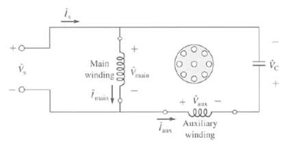
A 120-V, 60-Hz, capacitor-run, two-pole, single-phase induction motor has the following parameters: Lmain = 47.2 mH Rmain = 0.38?, Laux = 102 mH Raux = 1.78?, Lr = 2.35?H R r = 17.2??, Lmain, r = 0.342 mH Laux, r = 0.530 mH. You may assume that the motor has 48 W of core loss and 23 W of rotational
Consider the single-phase motor of Problem 9.13. Write a MATLAB script to search over the range of capacitor values from 25μF to 75μF to find the value which will maximize the motor efficiency at a motor speed of 3490 r/min. What is the corresponding maximum efficiency?
In order to raise the starting torque, the single-phase induction motor of Problem 9.13 is to be converted to a capacitor-start, capacitor-run motor. Write a MATLAB script to find the minimum value of starting capacitance required to raise the starting torque to 0.5 N · m.
Consider the single-phase induction motor of Example 9.5 operating over the speed range 3350r/min to 3580r/min.a. Use MATLAB to plot the output power over the given speed range.b. Plot the efficiency of the motor over this speed range.c. On the same plot as that of part (b), plot the motor
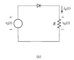
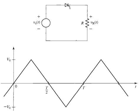
Consider the half-wave rectifier circuit of Figure a. The circuit is driven by a triangular voltage source Vs (t) of amplitude V0 = 9 V as shown in Fig. 10.50. Assuming the diode to be ideal and for a resistor R = 1.5 k?: a. Plot the resistor voltage VR (t). b. Calculate the rms value of the
Repeat Problem 10.1 assuming the diode to have a fixed 0.6 V voltage drop when it is ON but to be otherwise ideal. In addition, calculate the time-averaged power dissipation in the diode.
Consider the half-wave SCR rectifier circuit of Figure supplied from the triangular voltage source of Figure. Assuming the SCR to be ideal, calculate the rms resistor voltage as a function of the firing-delay time td (0 td T/2).
Consider the rectifier system of Example 10.5. Write a MATLAB script to plot the ripple voltage as a function of filter capacitance as the filter capacitance is varied over the range 3000μF < C < 105μF. Assume the diode to be ideal. Use a log-scale for the capacitance.
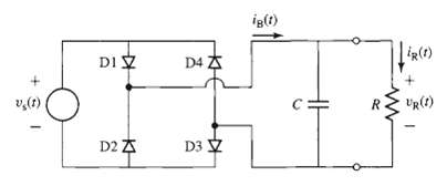
Consider the full-wave rectifier system of Figure with R = 500 fl and C = 200?F. Assume each diode to have a constant voltage drop of 0.7 V when it is ON but to be otherwise ideal. For a 220 V rms, 50 Hz sinusoidal source, write a MATLAB script to calculate a. The peak voltage across the load
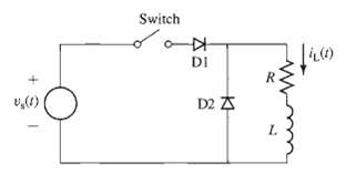
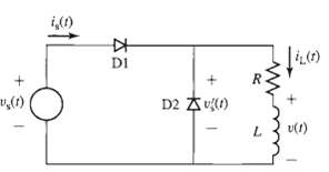
Consider the half-wave rectifier system of Figure. The voltage source is Vs (t) = V0 sin wt where V0 = 15 V, and the frequency is 100 Hz. For L = 1 mH and R = 1?, plot the inductor current iL (t) for the first 1-1/2 cycles of the applied waveform assuming the switch closes at time t = 0.
Repeat Problem 10.6, using MATLAB to plot the inductor current for the first 10 cycles following the switch closing at time t = 0.
Consider the half-wave rectifier system of Figure as L becomes sufficiently large such that co (L/R) >> 1, where co is the supply frequency. In this case, the inductor current will be essentially constant. For R = 5? and Vs (t) = V0 sin wt where V0 = 45 V and w = 100? rad/sec. Assume the
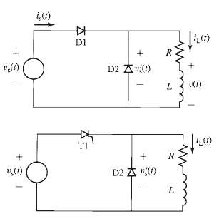
Consider the half-wave, phase-controlled rectifier system of Figure. This is essentially the same circuit as that of Problem 10.8 with the exception that diode D1 of Figure has been replaced by an SCR, which you can consider to be ideal. Let R = 5? and Vs (t) = V0 sin wt, where V0 = 45 V and w =
Showing 1500 - 1600
of 3459
First
9
10
11
12
13
14
15
16
17
18
19
20
21
22
23
Last
Step by Step Answers