New Semester
Started
Get
50% OFF
Study Help!
--h --m --s
Claim Now
Question Answers
Textbooks
Find textbooks, questions and answers
Oops, something went wrong!
Change your search query and then try again
S
Books
FREE
Study Help
Expert Questions
Accounting
General Management
Mathematics
Finance
Organizational Behaviour
Law
Physics
Operating System
Management Leadership
Sociology
Programming
Marketing
Database
Computer Network
Economics
Textbooks Solutions
Accounting
Managerial Accounting
Management Leadership
Cost Accounting
Statistics
Business Law
Corporate Finance
Finance
Economics
Auditing
Tutors
Online Tutors
Find a Tutor
Hire a Tutor
Become a Tutor
AI Tutor
AI Study Planner
NEW
Sell Books
Search
Search
Sign In
Register
study help
engineering
electrical engineering
Basic Engineering Circuit Analysis 9th Edition J. David Irwin - Solutions
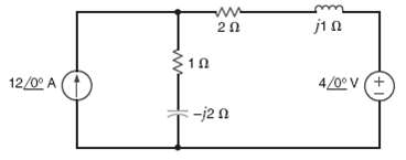
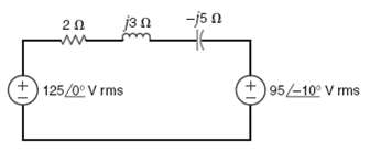
Given the network in figure, find the average power supplied to the circuit.
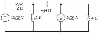
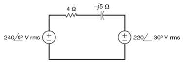
Determine the average power absorbed by the 4-? resistor in the network shown in figure.
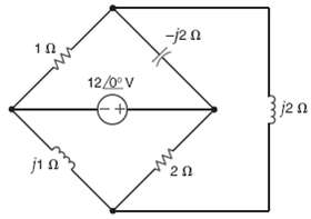
Given the network in figure find the average power supplied and the total average power absorbed.
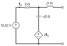
Determine the average power absorbed by a 2-? resistor connected at the output terminals of the network shown in figure.
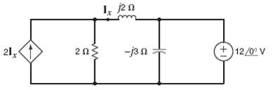
Find the average power absorbed by the 2-? resistor in the circuit shown in figure.
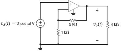
Determine the average power absorbed by the 4-k? resistor in figure.
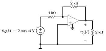
Determine the average power absorbed by the 2-k? output resistor in figure.
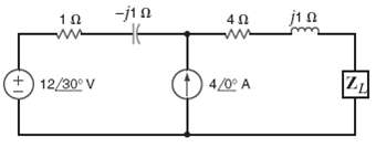
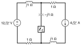
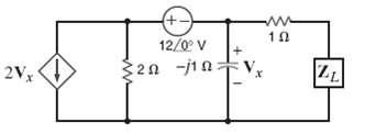
Determine the impedance ZL for maximum average power transfer and the value of the maximum power transferred to ZL for the circuit shown infigure.
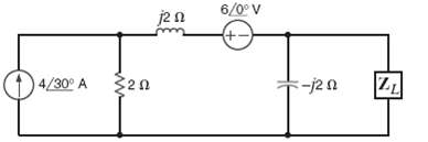
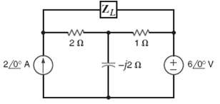
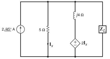
Determine the impedance ZL for maximum average power transfer and the value of the maximum average power transferred to ZL for the circuit shown infigure.
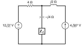
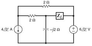
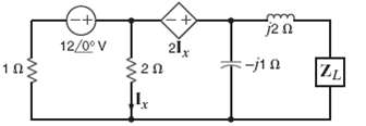
Determine the impedance ZL for maximum average power transfer and the value of the maximum average power absorbed by the load in the network shown infigure.
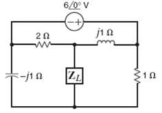
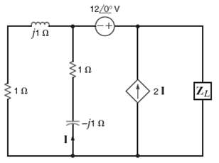
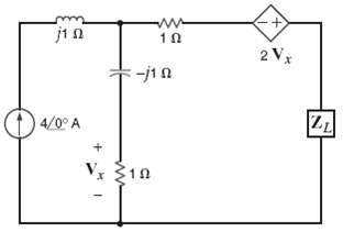
Determine the impedance ZL for maximum average power transfer and the value of the maximum average power transferred to ZL for the circuit shown infigure.
Determine the impedance ZL for maximum average power transfer and the value of the maximum average power absorbed by the load in the network shown infigure.
In the network in figure find ZL for maximum average power transfer and the maximum average power transferred.
In the network in figure, find ZL for maximum average power transfer and the maximum average power transferred.
In the network in figure, find ZL for maximum average power transfer and the maximum average power transferred.
Find the impedance ZL for maximum average power transfer and the value of the maximum average power transferred to ZL for the circuit shown in figure.
Determine the impedance ZL for maximum average power transfer and the value of the maximum average power absorbed by the load in the network shown infigure.
Find the value of ZL in the circuit in figure for maximum average power transfer.
Determine the impedance ZL for maximum average power transfer and the value of the maximum average power absorbed by the load in the network shown infigure.
Repeat Problem for the network infigure.
Compute the rms value of the voltage given by the expression v(t) = 10 + 20 cos (377t + 30o) V.
Find the rms value of the voltage defined by the expression v(t) = cos t + cos (t + 120o)
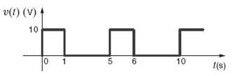
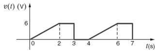
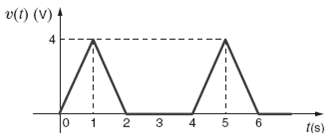
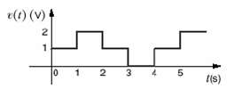
Compute the rms value of the voltage given by the wave form shown in figure.
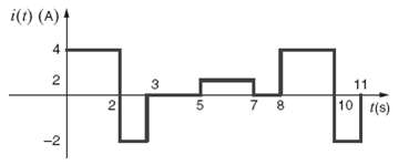
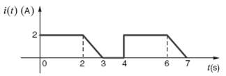
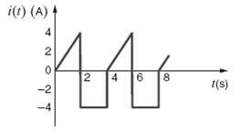
Calculate the rms value of the periodic current waveform shown infigure.
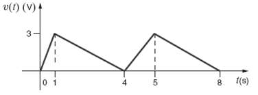
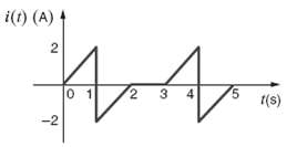
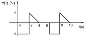
Calculate the rms value of the waveform shown infigure.
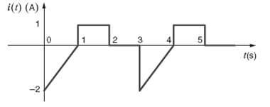
Calculate the rms value of the waveform shown infigure
Calculate the rms value of the waveform infigure.
Calculate the rms value of the waveform infigure.
Find the rms value of the waveform shown infigure.
Calculate the rms value of the waveform infigure.
Calculate the rms value of the waveform shown infigure.
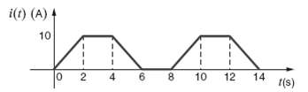
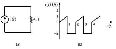
The current waveform in figure is flowing through a 5-? resistor. Find the average power absorbed by the resistor.
Compute the rms value of the waveform infigure.
Calculate the rms value of the waveform shown infigure.
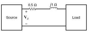
An industrial load consumes 100kW at 0.8 pf lagging. If an ammeter in the transmission line indicates that the load current is 200 A rms, find the load voltage.
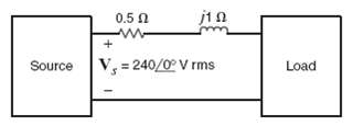
A plant consumes 20kW of power from a 240-V rms line. If the load power factor is 0.9, what is the angle by which the load voltage leads the load current? What is the load current phasor if the line voltage has a phasor of 240 <0o V rms?
A plant consumes 100kW of power at 0.9 pf lagging. If the load current is 200 A rms, find the load voltage.
An industrial plant with an inductive load consumes 10kW of power from a 220-V rms line. If the load power factor is 0.8, what is the angle by which the load voltage leads the load current?
A plant draws 250 A rms from a 240-V rms line to supply a load with 50kW. What is the power factor of the lead?
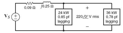
The power company must generate 100kW to supply an industrial load with 94kW through a transmission line with 0.09-Ω resistance. If the load power factor is 0.83 lagging, find the load voltage.
A transmission line with impedance of 0.08 + j0.25 Ω is used to deliver power to a load. The load is inductive and the load voltage is 220 <0o V rms at 60 Hz. If the load requires 12kW and the real power loss in the line is 560 W, determine the power factor angle of the load
The power company supplies 80kW to an industrial load. The load draws 220 A rms from the transmission line. If the load voltage is 440 V rms and the load power factor is 0.8 lagging, find the losses in the transmission line.
The power company supplies 40kW to an industrial load. The Load draws 200 A rms from the transmission line. If the load voltage is 240V rms and the load power factor is 0.8 lagging, find the losses in the transmission line.
An industrial load that consumes 40 kW is supplied by the power company, through a transmission line with 0.1-Ω resistance, with 44kW. If the voltage at the load is 240 V rms, find the power factor at the load.
A transmission line with impedance 0.1 + j0.2 Ω is used to deliver power to a load. The load is capacitive and the load voltage is 240 < 0o V rms at 60 Hz. IF the load requires 15kW and the real power loss in the line is 660 W, determine the input voltage to the line.
An industrial load operates at 30kW, 0.8 pf lagging. The load voltage is 240 < 0o V rms. The real and reactive power losses in the transmission-line feeder are 1.8kW and 2.4kvar, respectively. Find the impedance of the transmission line and the input voltage to the line.
Find the real and reactive power absorbed by each element in the circuit infigure.
Find the real and reactive power absorbed by each element in the circuit infigure.
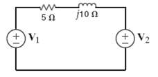
In the circuit in figure, the complex power supplied by source S1 is 2000
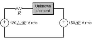
For the network in figure, the complex power absorbed by the source on the right is 0 + j1582.5 VA. Find the value of R and the unknown element and its value if f = 60 Hz. (If the element is a capacitor, give its capacitance; if the element is an inductor, give usinductance)
The load in the diagram in figure may be modeled by two elements connected in parallel-either a resistor and an inductor or a resistor and a capacitor. Determine which model is appropriate for this load and determine values for R and either L or C if f = 60 Hz and the source supplies 12kW at a pf =
Given the circuit in figure, find the power factor at the source and vs(t), if f =60Hz.
Given the diagram in figure, the source supplies 12kW at a power factor of 0.8 lagging, determine the complex power absorbed by the load if Vs = 240
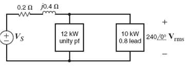
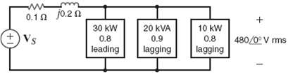
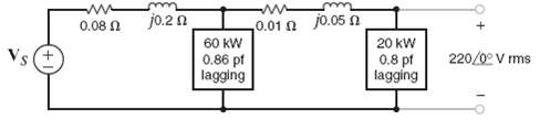
Given the network in figure, find the complex power supplied by the source the power factor of the source, and the voltage vs(t). The frequency is60Hz.
Use Kirchhof 's laws to compute the source voltage of the network shown infigure.
Given the network in figure, determine the input voltage Vs.
Given the network in figure determine the input voltageVs.
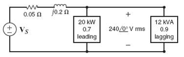
Given the circuit in figure, find the complex power supplied by the source and the source power factor. If f = 60Hz, findvs(t).
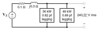
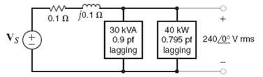
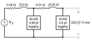
Given the network in figure compute the input source voltage and the input power factor?
Given the network in figure compute the input source voltage and the input power factor?
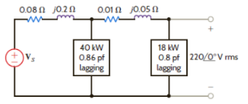
What value of capacitance must be placed in parallel with the 18-kW load in problem 9.65 to raise the power factor of this load to 0.9 lagging?Data from 9.65Compute the input source voltage and the input power factor.
An industrial load consumes 44kW at 0.82 pf lagging from a 240<0o – V rms 60-Hz line. A bank of capacitors totaling 600μF is available. If these capacitors are placed in parallel with the load, what is the new power factor of the total load?
A particular load has a pf 0.8 lagging. The power delivered to the load is 40kW from a 270-V rms 60-Hz line. What value of capacitance placed in parallel with the load will raise the pf to 0.9 lagging?
A bank of induction motors consumes 36kW at 0.78 pf lagging from a 60-Hz 240 < 0o V rms line. If 200μf of capacitors are placed in parallel with the load, what is the new power factor of the total load?
A plant consumes 60kW at a power factor of 0.75 lagging from a 240-V rms 60-Hz line. Determine the value of the capacitor that when placed in parallel with the load will change the load power factor to 0.9 lagging.
The 60-Hz line voltage for a 60-kW, 0.76-pf lagging industrial load is 240 < 0o V rms. Find the value of capacitance that when placed in parallel with the load will raise the power factor to 0.9 lagging.
An industrial load is supplied through a transmission line that has a line impedance of 0.1 + j0.02 Ω. The 60-Hz line voltage at the load is 480<0o V rms. The load consumes 124kW at 0.75 pf lagging. What value of capacitance when placed in parallel with the load will change the power factor to
A particular load has a pf of 0.8 lagging. The power delivered to the load is 40kW from a 220-V rms 60-Hz line, what value of capacitance placed in parallel with the load will raise the pf to 0.9 lagging?
Use an RC combination to design a circuit that will reduce a 120-V rms line voltage to a voltage between 75 and 80 V rms while dissipating less than 30 W.
A 5-kW load operates at 60Hz, 240-V rms and has a power factor of 0.866 lagging. We wish to create a power factor of at least 0.975 lagging using a single capacitor. Can this requirement be met using a single capacitor from Table 6.1?
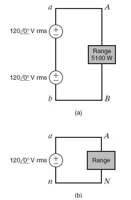
A 5-1-kW household range is designed to operate on a 240-V rms sinusoidal voltage, as shown in figure. However, the electrician has mistakenly connected the range to 120V rms, as shown in figure. What is the effect of thiserror?
To test a light socket, a woman, while standing on cushions that insulate her from the ground, sticks her finger into the socket, as shown in figure. The tip of her finger makes contact with one side of the line, and the side of her finger makes contact with the other side of the line. Assuming
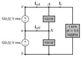
A single-phase three-wire 6-Hz circuit serves three loads, as shown in figure. Determine IaA, InN, Ic, and the energy use over a 24-hour period inkilowatt-hours.
A number of 120-V rms household fixtures are to be used to provide lighting for a large room the total lighting for a large room. The National Electric Code requires that no circuit breaker be larger than 20 A rms with a 25% safety margin. Determine the number of identical branch circuits needed
A man and his son are flying a kite. The kite becomes entangled in a 7200-V rms power line close to a power pole. The man crawls up the pole to remove the kite. While trying to remove the kite, the man accidentally touches the 7200-V rms line. Assuming the power pole is well grounded, what is the
An industrial load consumes 120kW at 0.707 pf lagging and is connected to a 780< 0oV rms 60-Hz line. Determine the value of the capacitor that, when connected in parallel with the load, will raise the power factor to 0.95 lagging.a. 642μFb. 763μFc. 928μFd. 471μF
Determine the rms value of the following waveform. a. 2.33V b. 1V c. 3.25V d. 1.22V
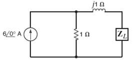
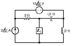
Find the impedance ZL in the network in figure for maximum power transfer. a. 0.8 + j2.4? b. 0.4 ? j1.2? c. 0.2 + j1.4? d. 0.3 ? j1.6?
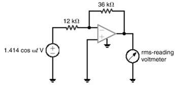
An rms-reading voltmeter is connected to the output of the op-amp shown in figure. Determine the meter reading. a. 3 V b. 5.2 V c. 4.24 V d. 2V
Determine the average power delivered to the resistor in figure a, if the current waveform is shown in figure b. a. 18.78 W b. 8.64 W c. 2.82 W d. 10.91W
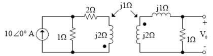
Find V0 in the network infigure.
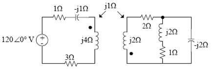
Determine the impedance seen by the source in the circuit infigure.
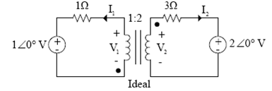
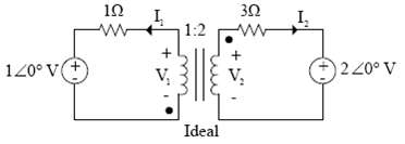
Determine I1, I2, V1 and V2 in the circuit in figure.
Given the circuit in figure, determine the two networks obtained by replacing (a) The primary and the ideal transformer with an equivalent circuit and (b) The ideal transformer and the secondary with an equivalentcircuit.
Sketch a phasor representation of a balanced three-phase system containing both phase voltages and line voltages if V an = 120 <90o V rms. Label all magnitudes and assume an abc-phase sequence.
Sketch a phasor representation of an abc-sequence balanced three-phase Y-connected source, including Van, Vbn, and Vcn if Van = 120 < 15oV rms.
Sketch a phasor representation of a balanced three-phase system containing both phase voltages and line voltages if Vab = 208 (60o V) rms. Label all phasors and assume an abc-phase sequence.
Sketch a phasor representation of a balanced three-phase system containing both phase voltages and line voltages if Van = 100 < 45o V rms. Label all magnitudes and assume and abc-phase sequence.
Sketch a phasor representation of a balanced three-phase system containing both phase voltages and line voltages if Van = 100 < 45o V rms. Label all magnitudes and assume and abc-phase sequence.
A positive-sequence balanced three-phase wye-connected source with a phase voltage of 120 V rms supplies power to a balanced wye-connected load. The per phase load impedance is 40 + j10Ω. Determine the line currents in the circuit if < Van = 0o.
In a balanced three-phase system, the abc-phase-sequence source is delta connected and Vab = 120 <30o V rms. The load consists of two balanced wyes with phase impedances of 10 + j1 Ω and 20 + j5 Ω. If the line impedance is zero, find the line currents and the load phase voltage.
An abc-sequence balanced three-phase wye-connected source supplies power to a balanced wye-connected load. The line impedance per phase is 1 + j5Ω, and the load impedance per phase is 25 + j25Ω. If the source line voltage Van is 208 <0o V rms, find the line currents.
In a three-phase balanced delta-delta system, the source has an abc-phase sequence. The line and load impedances are 0.5 + 0.1 j Ω and 10 + j5 Ω, respectively. If VAB = 115 <30oV rms, find the phase voltage of the sources.
An abc-sequence balanced three-phase wye-connected source supplies power to a balanced wye-connected load. The line impedance per phase is 1 + j10Ω, and the load impedance per phase is 20 + j20Ω. If the source line voltage Vab is 100 <0oV rms, find the line currents.
In a balance three-phase wye-wye system, the source is an abc-sequence set of voltages. The load voltage on the a phase is VAN = 110<80o V rms, Z line =1 + j1.4Ω, and Z load = 10 + j 13Ω. Determine the input sequence of the line-to-neutral voltages.
In a balance three-phase wye-wye system, the source is an abc-sequence set of voltages. The load voltage on the a phase is VAN = 110<80o V rms, Z line = 1 + j1.4Ω, and Z load = 10 + j13Ω. Determine the input sequence of the line-to-neutral voltages.
In a balance three-phase wye-wye system, the source is an abc-sequence set of voltages. Z load = 1 + j1 Ω Z load = 14 + j12 Ω, and the load voltage on the a phase is VAN = 440 <30o V rms. Find the line voltage Vab.
A balanced abc-sequence of voltages feeds a balanced three-phase wye-wye system. The line and load impedance are 0.6 + j0.9Ω and 8 + j12Ω, respectively. The load voltage on the a phase is VAN = 116.63<10o V rms. Find the line voltage Vab.
In a balanced three-phase wye-way system, the load impedance is 8 + j4Ω. The source has phase sequence abc and Van = 120 <0o V rms. If the load voltage is VAN = 111.62 < – 1.33o V rms, determine the line impedance.
In a balanced three-phase wye-wye system the total power loss in the lines is 400W. VAN = 105.28<31.56o V rms and the power factor of the load is 0.77 lagging. If the line impedance is 2 + j1 Ω, determine the load impedance.
Showing 2400 - 2500
of 3459
First
18
19
20
21
22
23
24
25
26
27
28
29
30
31
32
Last
Step by Step Answers