New Semester
Started
Get
50% OFF
Study Help!
--h --m --s
Claim Now
Question Answers
Textbooks
Find textbooks, questions and answers
Oops, something went wrong!
Change your search query and then try again
S
Books
FREE
Study Help
Expert Questions
Accounting
General Management
Mathematics
Finance
Organizational Behaviour
Law
Physics
Operating System
Management Leadership
Sociology
Programming
Marketing
Database
Computer Network
Economics
Textbooks Solutions
Accounting
Managerial Accounting
Management Leadership
Cost Accounting
Statistics
Business Law
Corporate Finance
Finance
Economics
Auditing
Tutors
Online Tutors
Find a Tutor
Hire a Tutor
Become a Tutor
AI Tutor
AI Study Planner
NEW
Sell Books
Search
Search
Sign In
Register
study help
engineering
electrical engineering
Electric Machinery 6th Edition Charles Kingsley, Jr, Stephen D. Umans - Solutions
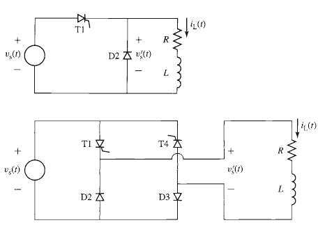
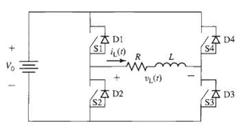
The half-wave, phase-controlled rectifier system of Problem 10.9 and Figure is to be replaced by the full-wave, phase-controlled system of Figure. SCR T1 will be triggered ON at time td (0 td ?/w), and SCR T4 will be triggered on exactly one half cycle later. a. Find an expression for the average
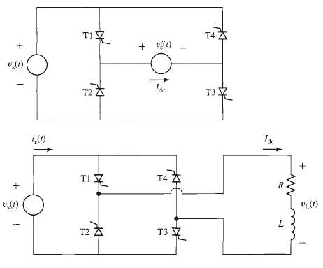
The full-wave, phase-controlled rectifier of Figure is supplying a highly inductive load such that the load current can be assumed to be purely dc, as represented by the current source Idc in the figure. The source voltage is a sinusoid, Vs (t) = V0 sin wt. As shown in Figure, SCRs T1 and T3 are
A full-wave diode rectifier is fed from a 50-Hz, 220-V rms source whose series inductance is 12 mH. It drives a load with a resistance 8.4Ω which is sufficiently inductive that the load current can be considered to be essentially dc.a. Calculate the dc load current Idc and the commutation time t
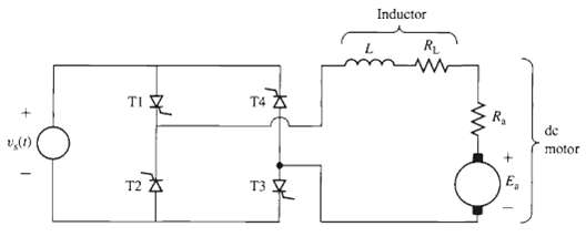
A 1-kW, 85-V, permanent-magnet dc motor is to be driven from a full-wave, phase-controlled bridge such as is shown in Figure. When operating at its rated voltage, the dc-motor has a no load speed of 1725 r/min and an armature resistance Ra = 0.82?. A large inductor (L = 580 mH) with resistance RL =
Consider the dc-motor drive system of Problem 10.13. To limit the starting current of the dc motor to twice its rated value, a controller will be used to adjust the initial firing-delay angle of the SCR Bridge. Calculate the required firing-delay angle αd.
A three-phase diode bridge is supplied by a three-phase autotransformer such that the line-to line input voltage to the bridge can be varied from zero to 230 V. The output of the bridge is connected to the shunt field winding of a dc motor. The resistance of this winding is 158Ω. The
A dc-motor shunt field winding of resistance 210Ω is to be supplied from a 220-V rms, 50-Hz, three-phase source through a three-phase, phase controlled rectifier. Calculate the delay angle αd which will result in a field current of 1.1 A.
A superconducting magnet has an inductance of 4.9 H, a resistance of 3.6 mΩ, and a rated operating current of 80 A. It will be supplied from a 15-V rms, three-phase source through a three phase, phase-controlled bridge. It is desired to "charge" the magnet at a constant rate to achieve rated
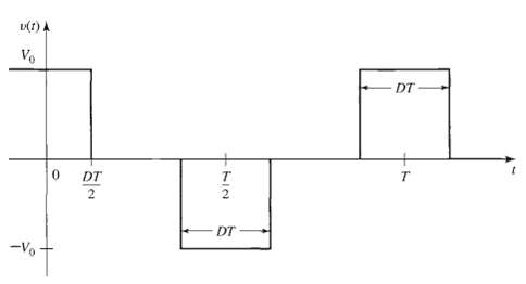
A voltage-source H-bridge inverter is used to produce the stepped waveform v (t) shown in Figure. For V0 = 50 V, T = 10 msec and D = 0.3: a. Using Fourier analysis, find the amplitude of the fundamental time harmonic component of v (t). b. Use the MATLAB 'fit ( )' function to find the amplitudes of
Consider the stepped voltage waveform of Problem 10.18 and Figure. a. Using Fourier analysis, find the value of D (0 D 0.5) such that the amplitude of the third harmonic component of the voltage waveform is zero. b. Use the MATLAB 'fit ( )' function to find the amplitudes of the first 10 time
Consider Example 10.12 in which a current-source inverter is driving a load consisting of a sinusoidal voltage. The inverter is controlled to produce the stepped current waveform shown in Figure. a. Create a table showing the switching sequence required to produce the specified waveform and the
A PWM inverter such as that of Figure is operating from a dc voltage of 75 V and driving a load with L = 53 mH and R = 1.7?. For a switching frequency of 1500 Hz, calculate the average load current, the minimum and maximum current, and the current ripple for a duty cycle D = 0.7.
The rotor of a six-pole synchronous generator is rotating at a mechanical speed of 1200 r/min.a. Express this mechanical speed in radians per second.b. What is the frequency of the generated voltage in hertz and in radians per second?c. What mechanical speed in revolutions per minute would be
The voltage generated in one phase of an unloaded three-phase synchronous generator is of the form v(t) = Vo cos cot. Write expressions for the voltage in the remaining two phases.
A three-phase motor is used to drive a pump. It is observed (by the use of a stroboscope) that the motor speed decreases from 898r/min when the pump is unloaded to 830 r/min as the pump is loaded.a. Is this a synchronous or an induction motor?b. Estimate the frequency of the applied armature
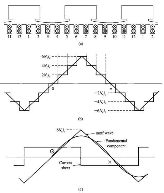
The object of this problem is to illustrate how the armature windings of certain machines, i.e., dc machines, can be approximately represented by uniform current sheets, the degree of correspondence growing better as the winding is distributed in a greater number of slots around the armature
A three-phase Y-connected ac machine is initially operating under balanced three-phase conditions when one of the phase windings becomes open-circuited. Because there is no neutral connection on the winding, this requires that the currents in the remaining two windings become equal and opposite.
What is the effect on the rotating mmf and flux waves of a three-phase winding produced by balanced-three-phase currents if two of the phase connections are interchanges?
In a balanced two-phase machine, the two windings are displaced 90 electrical degrees in space, and the currents in the two windings are phase-displaced 90 electrical degrees in time. For such a machine, carry out the process leading to an equation for the rotating mmf wave corresponding to Eq.
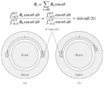
This problem investigates the advantages of short-pitching the stator coils of an ac machine. Figure shows a single full-pitch coil in a two-pole machine. Figure b shows a fractional-pitch coil for which the coil sides are ? radians apart, rather than ? radians (180?) as is the case for the
A six-pole, 60-Hz synchronous machine has a rotor winding with a total of 138 series turns and a winding factor kr = 0.935. The rotor length is 1.97 m, the rotor radius is 58 cm, and the air-gap length = 3.15 cm.a. What is the rated operating speed in r/min?b. Calculate the rotor-winding current
Assume that a phase winding of the synchronous machine of Problem 4.9 consists of one full-pitch, 11-turn coil per pole pair, with the coils connected in series to form the phase winding. If the machine is operating at rated speed and under the operating conditions of Problem 4.9, calculate the rms
The synchronous machine of Problem 4.9 has a three-phase winding with 45 series turns per phase and a winding factor kw = 0.928. For the flux condition and rated speed of Problem 4.9, calculate the rms-generated voltage per phase.
The three-phase synchronous machine of Problem 4.9 is to be moved to an application which requires that its operating frequency be reduced from 60 to 50 Hz. This application requires that, for the operating condition considered in Problem 4.9, the rms generated voltage equal 13.0 kV line-to-lines.
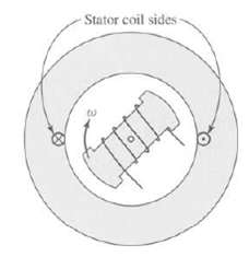
Figure shows a two-pole rotor revolving inside a smooth stator which carries a coil of 110 turns. The rotor produces a sinusoidal space distribution of flux at the stator surface; the peak value of the flux-density wave being 0.85 T when the current in the rotor is 15 A. The magnetic circuit is
A three-phase two-pole winding is excited by balanced three-phase 60-Hz currents as described by Eqs. 4.23 to 4.25. Although the winding distribution has been designed to minimize harmonics, there remains some third and fifth spatial harmonics. Thus the phase-a mmf can be written as Fa = ia (A1 cos
The nameplate of a dc generator indicates that it will produce an output voltage of 24 V dc when operated at a speed of 1200 r/min. By what factor must the number of armature turns be changed such that, for the same field-flux per pole, the generator will produce an output voltage of 18 V dc at a
The armature of a two-pole dc generator has a total of 320 series turns. When operated at a speed of 1800r/min, the open-circuit generated voltage is 240 V. Calculate Фp, the air-gap flux per pole.
The design of a four-pole, three-phase, 230-V, 60-Hz induction motor is to be based on a stator core of length 21 cm and inner diameter 9.52 cm. The stator winding distribution which has been selected has a winding factor kw = 0.925. The armature is to be Y-connected, and thus the rated phase
A two-pole, 60-Hz three-phase laboratory-size synchronous generator has a rotor radius of 5.71 cm, a rotor length of 18.0 cm, and an air-gap length of 0.25 mm. The rotor field winding consists of 264 turns with a winding factor of kr = 0.95. The Y-connected armature winding consists of 45 turns per
A four-pole, 60-Hz synchronous generator has a rotor length of 5.2 m, diameter of 1.24 m, and air-gap length of 5.9 cm. The rotor winding consists of a series connection of 63 turns per pole with a winding factor of kr = 0.91. The peak value of the fundamental air-gap flux density is limited to 1.1
Thermal considerations limit the field-current of the laboratory-size synchronous generator of Problem 4.18 to a maximum value of 2.4 A. If the peak fundamental air-gap flux density is limited to a maximum of 1.3 T, calculate the maximum torque (N ∙ m) and power (kW) which can be produced by this
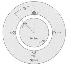
Figure shows in cross section a machine having a rotor winding f and two identical stator windings a and b whose axes are in quadrature. The self-inductance of each stator winding is Laa and of the rotor is Lff. The air gap is uniform. The mutual inductance between a stator winding depends on the
Consider the two-phase synchronous machine of Problem 4.22. Derive an expression for the torque acting on the rotor if the rotor is rotating at constant angular velocity, such that θ0 = wt + δ, and the phase currents become unbalanced such that ia = √2Ia cos wt ib = √2 (Ia + I')sin wt. What
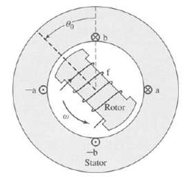
Figure shows in schematic cross section a salient-pole synchronous machine having two identical stator windings a and b on a laminated steel core. The salient-pole rotor is made of steel and carries a field winding f connected to slip rings. Because of the non-uniform air gap, the self- and mutual
A three-phase linear ac motor has an armature winding of wavelength 25 cm. A three-phase balanced set of currents at a frequency of 100 Hz is applied to the armature.a. Calculate the linear velocity of the armature mmf wave.b. For the case of a synchronous rotor, calculate the linear velocity of
The linear-motor armature of Problem 4.25 has a total active length of 7 wavelengths, with a total of 280 turns per phase with a winding factor kw = 0.91. For an air-gap length of 0.93 cm, calculate the rms magnitude of the balanced three-phase currents which must be supplied to the armature to
A two-phase linear permanent-magnet synchronous motor has an air-gap of length 1.0 mm, a wavelength of 12 cm, and a pole width of 4 cm. The rotor is 5 wavelengths in length. The permanent magnets on the rotor are arranged to produce an air-gap magnetic flux distribution that is uniform over the
The full-load torque angle of a synchronous motor at rated voltage and frequency is 35 electrical degrees. Neglect the effects of armature resistance and leakage reactance. If the field current is held constant, how would the full-load torque angle be affected by the following changes in operating
The armature phase windings of a two-phase synchronous machine are displaced by 90 electrical degrees in space.a. What is the mutual inductance between these two windings?b. Repeat the derivation leading to Eq. 5.17 and show that the synchronous inductance is simply equal to the armature phase
Design calculations show the following parameters for a three-phase, cylindrical-rotor synchronous generator: Phase-a self-inductance Laa = 4.83mH. Armature leakage inductance Lal = 0.33mH. Calculate the phase-phase mutual inductance and the machine synchronous inductance.
The open-circuit terminal voltage of a three-phase, 60-Hz synchronous generator is found to be 15.4 kV rms line-to-line when the field current is 420 A.a. Calculate the stator-to-rotor mutual inductance Laf.b. Calculate the open-circuit terminal voltage if the field current is held constant while
A 460-V, 50-kW, 60-Hz, three-phase synchronous motor has a synchronous reactance of Xs = 4.15 Ω and an armature-to-field mutual inductance, Laf = 83 mH. The motor is operating at rated terminal voltage and an input power of 40 kW. Calculate the magnitude and phase angle of the line-to-neutral
The motor of Problem 5.5 is supplied from a 460-V, three-phase source through a feeder whose impedance is Zf = 0.084 + j0.82Ω. Assuming the system (as measured at the source) to be operating at an input power of 40 kW, calculate the magnitude and phase angle of the line-to-neutral generated
A 50-Hz, two-pole, 750 kVA, 2300 V, three-phase synchronous machine has a synchronous reactance of 7.75 Ω and achieves rated open-circuit terminal voltage at a field current of 120 A.a. Calculate the armature-to-field mutual inductance.b. The machine is to be operated as a motor supplying a 600
The manufacturer's data sheet for a 26-kV, 750-MVA 60-Hz three-phase synchronous generator indicates that it has a synchronous reactance Xs = 2.04 and a leakage reactance Xal = 0.18, both in per unit on the generator base. Calculate(a) The synchronous inductance in mH,(b) The armature leakage
The following readings are taken from the results of an open- and a short-circuit test on an 800-MVA, three-phase, Y-connected, 26-kV, two-pole, 60-Hz turbine generator driven at synchronous speed: The number in parentheses are extrapolations based upon the measured data. Find(a) The short-circuit
The following readings are taken from the results of an open- and a short-circuit test on a 5000-kW, 4160-V, three-phase, four-pole, 1800-rpm synchronous motor driven at rated speed: The armature resistance is 11 m Ω/phase. The armature leakage reactance is estimated to be 0.12 per unit on the
Consider the motor of Problem 5.10.a. Compute the field current required when the motor is operating at rated voltage, 4200 kW input power at 0.87 power factor leading. Account for saturation under load by the method described in the paragraph relating to Eq. 5.29.b. In addition to the data given
Using MATLAB, plot the field current required to achieve unity-power-factor operation for the motor of Problem 5.10 as the motor load varies from zero to full load. Assume the motor to be operating at rated terminal voltage.
Loss data for the motor of Problem 5.10 are as follows: Open-circuit core loss at 4160 V = 37 kW. Friction and windage loss = 46 kW. Field-winding resistance at 75°C = 0.279Ω. Compute the output power and efficiency when the motor is operating at rated input power, unity power factor, and rated
The following data are obtained from tests on a 145-MVA, 13.8-kV, three phase, 60-Hz, 72-pole hydroelectric generator. Open-circuit characteristic: Short-circuit test: If = 710 A, Ia = 6070 Aa. Draw (or plot using MATLAB) the open-circuit saturation curve, the air-gap line, and the short-circuit
What is the maximum per-unit reactive power that can be supplied by a synchronous machine operating at its rated terminal voltage whose synchronous reactance is 1.6 per unit and whose maximum field current is limited to 2.4 times that required to achieve rated terminal voltage under open-circuit
A 25-MVA, 11.5 kV synchronous machines is operating as a synchronous condenser, as discussed in Appendix D (section D.4.1). The generator short-circuit ratio is 1.68 and the field current at rated voltage, no load is 420 A. Assume the generator to be connected directly to an 11.5 kV source.a. What
The synchronous condenser of Problem 5.17 is connected to a 11.5 kV system through a feeder whose series reactance is 0.12 per unit on the machine base. Using MATLAB, plot the voltage (kV) at the synchronous-condenser terminals as the synchronous-condenser field current is varied between 150 A and
A synchronous machine with a synchronous reactance of 1.28 per unit is operating as a generator at a real power loading of 0.6 per unit connected to a system with a series reactance of 0.07 per unit. An increase in its field current is observed to cause a decrease in armature current.a. Before the
Superconducting synchronous machines are designed with superconducting fields windings which can support large current densities and create large magnetic flux densities. Since typical operating magnetic flux densities exceed the saturation flux densities of iron, these machines are typically
For a synchronous machine with constant synchronous reactance Xs operating at a constant terminal voltage Vt and a constant excitation voltage Eaf, show that the locus of the tip of the armature-current phasor is a circle. On a phasor diagram with terminal voltage shown as the reference phasor,
A four-pole, 60-Hz, 24-kV, 650-MVA synchronous generator with a synchronous reactance of 1.82 per unit is operating on a power system which can be represented by a 24-kV infinite bus in series with a reactive impedance of j0.21 Ω. The generator is equipped with a voltage regulator that adjusts
The generator of Problem 5.22 achieves rated open-circuit armature voltage at a field current of 850 A. It is operating on the system of Problem 5.22 with its voltage regulator set to maintain the terminal voltage at 0.99 per unit (23.8 kV).a. Use MATLAB to plot the generator field current (in A)
The 145 MW hydroelectric generator of Problem 5.15 is operating on a 13.8-kV power system. Under normal operating procedures, the generator is operated under automatic voltage regulation set to maintain its terminal voltage at 13.8 kV. In this problem you will investigate the possible consequences
Repeat Example 5.9 assuming the generator is operating at one-half of its rated kVA at a lagging power factor of 0.8 and rated terminal voltage.
Repeat Problem 5.24 assuming that the saturated direct-axis synchronous inductance Xd is equal to that found in Problem 5.15 and that the saturated quadrature-axis synchronous reactance Xq is equal to 75 percent of this value. Compare your answers to those found in Problem 5.24.
Write a MATLAB script to plot a set of per-unit power-angle curves for a salient-pole synchronous generator connected to an infinite bus (V bus = 1.0 per unit). The generator reactances are Xd = 1.27 per unit and Xq = 0.95 per unit. Assuming Eaf = 1.0 per unit, plot the following curves:a.
Draw the steady-state, direct- and quadrature-axis phasor diagram for a salient-pole synchronous motor with reactances Xd and Xq and armature resistance Ra. From this phasor diagram, show that the torque angle δ between the generated voltage Eaf (which lies along the quadrature axis) and the
Repeat Problem 5.28 for synchronous generator operation, in which case the equation for δ becomes
What maximum percentage of its rated output power will a salient-pole motor deliver without loss of synchronism when operating at its rated terminal voltage with zero field excitation (Eaf = 0) if Xd = 0.90 per unit and Xq = 0.65 per unit? Compute the per-unit armature current and reactive power
If the synchronous motor of Problem 5.30 is now operated as a synchronous generator connected to an infinite bus of rated voltage, find the minimum per-unit field excitation (where 1.0 per unit is the field current required to achieve rated open-circuit voltage) for which the generator will remain
A salient-pole synchronous generator with saturated synchronous reactances Xd = 1.57 per unit and Xq = 1.34 per unit is connected to an infinite bus of rated voltage through an external impedance X bus = 0.11 per unit. The generator is supplying its rated MVA at 0.95 power factor lagging, as
A salient-pole synchronous generator with saturated synchronous reactances Xd = 0.78 per unit and Xq = 0.63 per unit is connected to a rated-voltage infinite bus through an external impedance X bus = 0.09 per unit. a. Assuming the generator to be supplying only reactive power(i) Find minimum
A two-phase permanent-magnet ac motor has a rated speed of 3000 r/min and a six-pole rotor. Calculate the frequency (in Hz) of the armature voltage required to operate at this speed.
A 5-kW, three-phase, permanent-magnet synchronous generator produces an open-circuit voltage of 208 V line-to-line, 60-Hz, when driven at a speed of 1800 r/min. When operating at rated speed and supplying a resistive load, its terminal voltage is observed to be 192 V line-to-lines for a power
Small single-phase permanent-magnet ac generators are frequently used to generate the power for lights on bicycles. For this application, these generators are typically designed with a significant amount of leakage inductance in their armature winding. A simple model for these generators is an ac
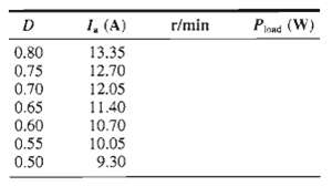
a. Calculate the field current required to achieve operation at 15.2 N · m torque and 1800 r/min. Calculate the corresponding PWM duty cycle D.b. Calculate the field current required to achieve operation at 15.2 N · m torque and 1500 r/min. Calculate the corresponding PWM duty cycle.c. Plot the
The dc motor of Problem 11.1 has a field-winding inductance Lf = 3.7 H and a moment of inertia J = 0.081 kg · m2. The motor is operating at rated terminal voltage and an initial speed of 1300 r/min.a. Calculate the initial field current If and duty cycle D. At time t = 0, the PWM duty cycle is
A shunt-connected 240-V, 15-kW, 3000 r/min dc motor has the following parameters Field resistance: R f = 132Ω, Armature resistance: Ra = 0.168Ω, Geometric constant: Kf = 0.422 V/ (A· rad/sec) When operating at rated voltage, no-load, the motor current is 1.56 A.a. Calculate the no-load speed and
The data sheet for a small permanent-magnet dc motor provides the following parameters" Rated voltage: Vrated = 3 V, Rated output power: Prated = 0.28 W, No-load speed: nnl = 12,400 r/min, Torque constant: Km = 0.218 mV/(r/min), Stall torque: Tstall = 0.094 oz · ina. Calculate the motor armature
The data sheet for a 350-W permanent-magnet dc motor provides the following parameters: Rated voltage: Vrated = 24 V, Armature resistance: Ra = 97 m?, No-load speed: nnl = 3580 r/min, No-load current: Ia, nl = 0.47 A a. Calculate the motor torque-constant Km in V/ (rad/sec). b. Calculate the
The motor of Problem 11.5 has a moment of inertia of 6.4 x 10⁻⁷ oz · in · sec2. Assuming it is unloaded and neglecting any effects of rotational loss, calculate the time required to achieve a speed of 12,000r/min if the motor is supplied by a constant armature current of 100 mA.
An 1100-W, 150-V, 3000-r/min permanent-magnet dc motor is to be operated from a current source inverter so as to provide direct control of the motor torque. The motor torque constant is Km = 0.465 V/ (rad/sec); its armature resistance is 1.37Ω. The motor rotational loss at a speed of 3000 r/min is
The permanent-magnet dc motor of Problem 11.8 is operating at its rated speed of 3000 r/min and no load. If rated current is suddenly applied to the motor armature in such a direction as to slow the motor down, how long will it take the motor to reach zero speed? The inertia of the motor alone is
A 1100-kVA, 4600-V, 60-Hz, three-phase, four-pole synchronous motor is to be driven from a variable-frequency, three-phase, constant V/Hz inverter rated at 1250-kVA. The synchronous motor has a synchronous reactance of 1.18 per unit and achieves rated open-circuit voltage at a field current of 85
Consider a three-phase synchronous motor for which you are given the following data: Rated line-to-line voltage (V), Rated volt-amperes (VA), Rated frequency (Hz) and speed (r/min), Synchronous reactance in per unit, Field current at rated open-circuit voltage (AFNL) (A). The motor is to be
For the purposes of performing field-oriented control calculations on non-salient synchronous motors, write a MATLAB script that will calculate the synchronous inductance Ls and armature-to field mutual inductance Laf, both in henries, and the rated torque in N · m, given the following data: Rated
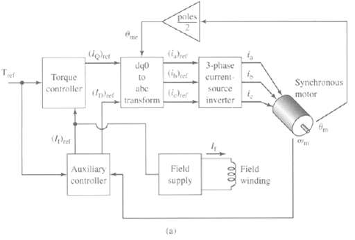
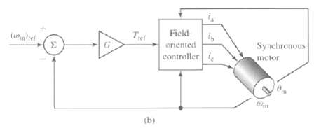
A 100-kW, 460-V, 60-Hz, four-pole, three-phase synchronous machine is to be operated as a synchronous motor under field-oriented torque control using a system such as that shown in Figure a. The machine has a synchronous reactance of 0.932 per unit and AFNL = 15.8 A. The motor is operating at rated
The synchronous motor of Problem 11.13 is operating under field-oriented torque control such that iD = 0. With the field current set equal to 14.5 A and with the torque reference set equal to 0.75 of the motor rated torque, the motor speed is observed to be 1475 r/min.a. Calculate the motor output
Consider the case in which the load on the synchronous motor in the field oriented torque-control system of Problem 11.13 is increased, and the motor begins to slow down. Based upon some knowledge of the load characteristic, it is determined that it will be necessary to raise the torque set point
Consider a 500-kW, 2300-V, 50-Hz, eight-pole synchronous motor with a synchronous reactance of 1.18 per unit and AFNL = 94 A. It is to be operated under field-oriented torque control using the unity-power-factor algorithm described in the text following Example 11.8. It will be used to drive a load
A 2-kVA, 230-V, two-pole, three-phase permanent magnet synchronous motor achieves rated open-circuit voltage at a speed of 3500 r/min. Its synchronous inductance is 17.2 mH.a. Calculate APM for this motor.b. If the motor is operating at rated voltage and rated current at a speed of 3600 r/min,
Field-oriented torque control is to be applied to the permanent-magnet synchronous motor of Problem 11.18. If the motor is to be operated at 4000 r/min at rated terminal voltage, calculate the maximum torque and power which the motor can supply and the corresponding values of iD and iQ.
A 15-kVA, 230-V, two-pole, three-phase permanent-magnet synchronous motor has a maximum speed of 10,000 r/min and produces rated open-circuit voltage at a speed of 7620 r/min. It has a synchronous inductance of 1.92 mH. The motor is to be operated under field-oriented torque control.a. Calculate
The permanent magnet motor of Problem 11.17 is to be operated under vector control using the following algorithm. Terminal voltage not to exceed rated value, Terminal current not to exceed rated value iD = 0 unless flux weakening is required to avoid excessive armature voltage. Write a MATLAB
Consider a 460-V, 25-kW, four-pole, 60-Hz induction motor which has the following equivalent-circuit parameters in ohms per phase referred to the stator: R1 = 0.103 R2 = 0.225 X1 = 1.10 X2 = 1.13 Xm = 59.4. The motor is to be operated from a variable frequency, constant-V/Hz drive whose output is
Consider the 460-V, 250-kW, four-pole induction motor and drive system of Problem 11.21.a. Write a MATLAB script to plot the speed-torque characteristic of the motor at drive frequencies of 20, 40, and 60 Hz for speeds ranging from -200r/min to the synchronous speed at each frequency.b. Determine
A 550-kW, 2400-V, six-pole, 60-Hz three-phase induction motor has the following equivalent circuit parameters in ohms-per-phase-Y referred to the stator: R1 = 0.108 R2 = 0.296 X1 = 1.18 X2 = 1.32 Xm = 48.4. The motor will be driven by a constant-V/Hz drive whose voltage is 2400 V at a frequency of
A 150-kW, 60-Hz, six-pole, 460-V three-phase wound-rotor induction motor develops full load torque at a speed of 1157 r/min with the rotor short circuited. An external non-inductive resistance of 870 mΩ is placed in series with each phase of the rotor, and the motor is observed to develop its
The wound rotor of Problem 11.24 will be used to drive a constant-torque load equal to the rated full-load torque of the motor. Using the results of Problem 11.24, calculate the external rotor resistance required to adjust the motor speed to 850r/min.
A 75-kW, 460-V, three-phase, four-pole, 60-Hz, wound-rotor induction motor develops a maximum internal torque of 212 percent at a slip of 16.5 percent when operated at rated voltage and frequency with its rotor short-circuited directly at the slip tings. Stator resistance and rotational losses may
A 35-kW, three-phase, 440-V, six-pole wound-rotor induction motor develops its rated full load output at a speed of 1169 r/min when operated at rated voltage and frequency with its slip rings short-circuited. The maximum torque it can develop at rated voltage and frequency is 245 percent of full
a. The value of the peak direct- and quadrature-axis components of the armature currents iD and iQ.b. The rms armature current under this operating condition.c. The electrical frequency of the drive in Hz.d. The rms line-to-line armature voltage.
Showing 1600 - 1700
of 3459
First
10
11
12
13
14
15
16
17
18
19
20
21
22
23
24
Last
Step by Step Answers