New Semester
Started
Get
50% OFF
Study Help!
--h --m --s
Claim Now
Question Answers
Textbooks
Find textbooks, questions and answers
Oops, something went wrong!
Change your search query and then try again
S
Books
FREE
Study Help
Expert Questions
Accounting
General Management
Mathematics
Finance
Organizational Behaviour
Law
Physics
Operating System
Management Leadership
Sociology
Programming
Marketing
Database
Computer Network
Economics
Textbooks Solutions
Accounting
Managerial Accounting
Management Leadership
Cost Accounting
Statistics
Business Law
Corporate Finance
Finance
Economics
Auditing
Tutors
Online Tutors
Find a Tutor
Hire a Tutor
Become a Tutor
AI Tutor
AI Study Planner
NEW
Sell Books
Search
Search
Sign In
Register
study help
engineering
electrical engineering
Basic Engineering Circuit Analysis 9th Edition J. David Irwin - Solutions
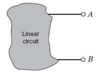
Given the linear circuit in figure, it is known that when a 2-k? load is connected to the terminals A ? B, the load current is 10mA. If a 10-k? load is connected to the terminals, the load current is 6 mA. Find the current in a 20-k? load.
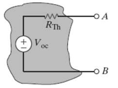
If an 8-k? load is connected to the terminals of the network in figure, VAB = 16?. If a 2-k? load is connected to the terminals, VAB = 8V. Find VB if a 20-k? load is connected to the terminals.
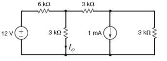
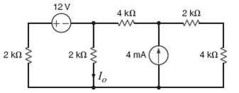
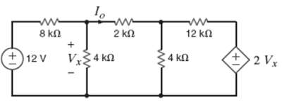
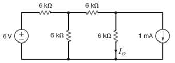
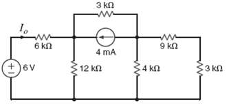
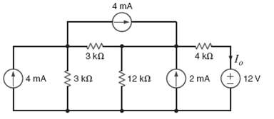
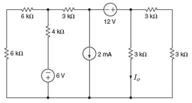
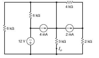
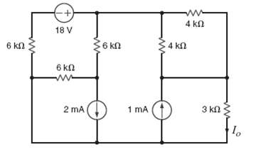
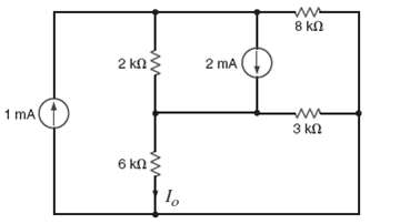
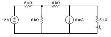
Find Io in the network in figure using Norton?s theorem.
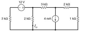
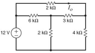
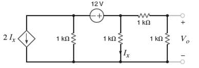
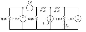
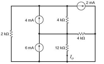
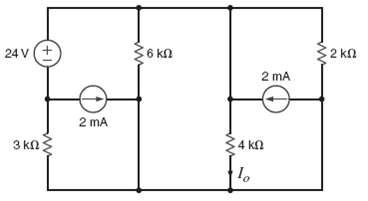
Use Norton?s theorem to find Io in the circuit in figure.
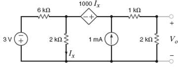
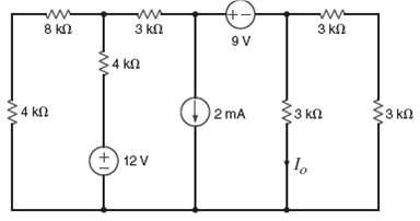
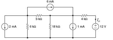
Use Norton?s theorem to find Io in the circuit in figure.
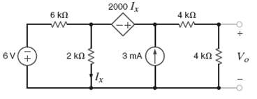
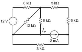
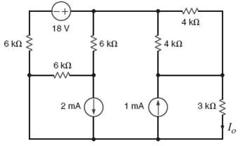
Find Io in the network in figure using Norton?s theorem.
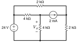
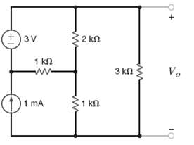
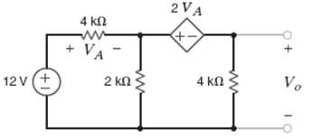
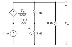
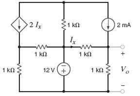
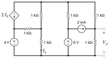
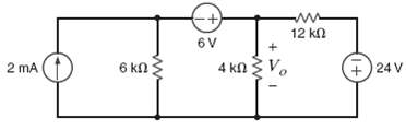
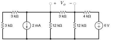
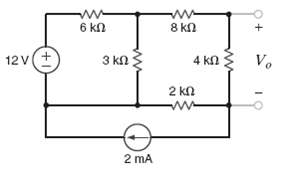
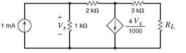
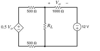
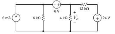
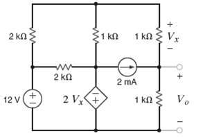
Use Norton?s theorem to find Vo in the network in figure.
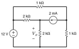
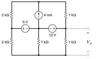
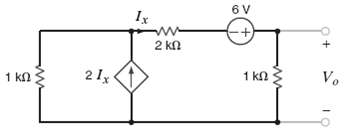
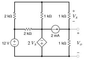
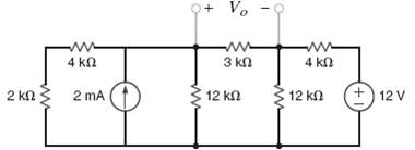
Use Norton?s theorem to find Vo?in the network in figure.
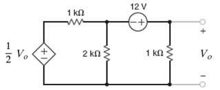
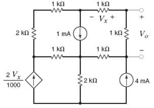
Find Vo in the network in figure using Norton?s theorem.
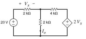
Use Norton?s theorem to find Io in the circuit in figure.
Find Vo in the circuit in figure using Norton?s theorem.
Use Norton?s theorem to find Io in the network figure.
Use Norton?s theorem to find Io in the circuit in figure.
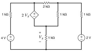
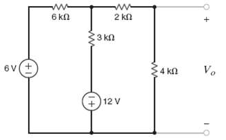
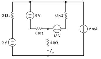
Find Vo?in the network in figure using Thevenin?s theorem.
Use Thevenin?s theorem to find Vo in the circuit in figure.
In the network in figure find, Vo using Thevenin?s theorem.
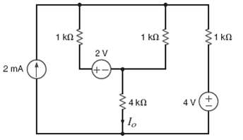
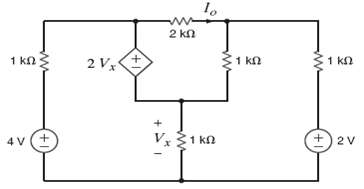
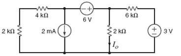
Use Thevenin?s in theorem to find Io in the circuit in figure.
Use Thevenin?s theorem to find Io in the circuit in figure.
Use Thevenin?s theorem to find Vo in the circuit in figure.
Find Vo in the network in figure using Thevenin?s theorem.
Norton?s theorem to find Vo in the network in figure.
Find Vo in the circuit in figure using Thevenin?s theorem.
Find Vo in the network in figure using Norton?s theorem.
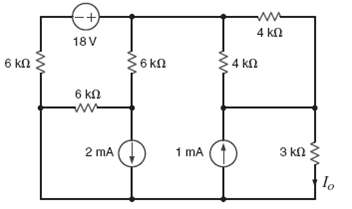
Find Io in the network in figure using Thevenin?s theorem.
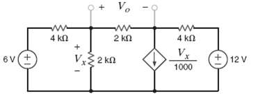
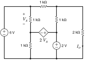
Use Thevenin?s theorem to find the power supplied by the 2-V source in the circuit in figure.
Find Vo in the circuit in figure using Thevenin?s theorem.
Find Vo in the network in figure using Thevenin?s theorem.
Find Vo in the network of figure using Thevenin?s theorem
Use Thevenin?s theorem to find Io in the network in figure.
Use Thevenin?s theorem to find Vo in the network in figure.
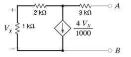
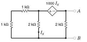
Find the Thevenin equivalent of the circuit in figure at the terminals A-B.
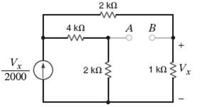
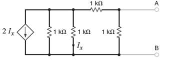
Find the Thevenin equivalent of the network in figure at the terminals A-B using a 1-mA current source.
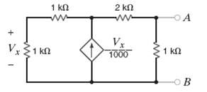
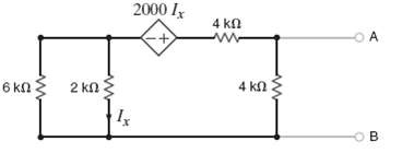
Find the Thevenin equivalent of the network in figure at the terminals A-B.
Find the Thevenin equivalent of the network in figure at the terminals A-B.
Find the Thevenin equivalent of the network below at the terminals A-B in figure.
Find the Thevenin equivalent circular of the network in figure at terminals A-B.
Find Io in the network in figure using source transformation.
Use source transformation to find Vo in the network in figure.
Find Io in the network in figure using source transformation.
Find Vo in the network in figure using source transformation.
Use source transformation to fin Io in the network in figure.
Find Vo in the network in figure using source transformation.
Find Vo in the circuit in figure using source transformation.
Find Io in the circuit in figure using source transformation.
Find Io in the circuit in figure using source transformation.
Find Io in the circuit in figure using source transformation.
Find Io in the circuit in figure using source transformation.
Find Io in the circuit in figure using source transformation.
Use source transformation find Io in the network in figure.
Using source transformation, find Vo in the circuit in figure.
Using source transformation, find Io in the circuit in figure.
Use source transformation to find Io in the circuit in figure.
Using source transformation, find Io in the network in figure.
Using source transformation, find Io in the network in figure.
Use source transformation to find Io in the circuit in figure.
Using source transformation, find Io in the network in figure.
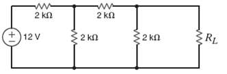
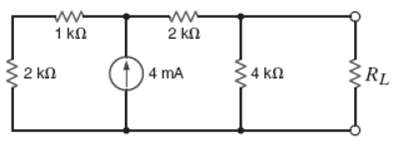
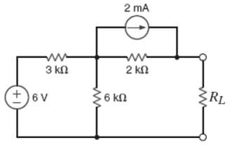
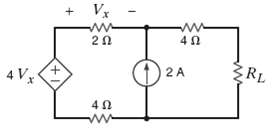
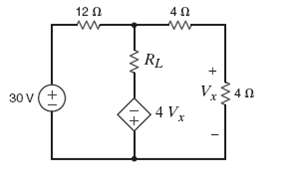
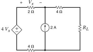
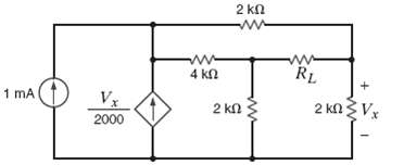
Find RL in the network in figure in order to achieve maximum power transfer.
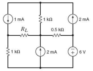
In the network in figure find RL for maximum power transfer and the maximum power transferred to this load.
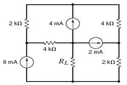
Find RL for maximum power transfer and the maximum power that can be transferred to the load in figure.
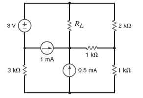
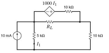
Find RL for maximum power transfer and the maximum power that can be transferred to the load in the circuit in figure.
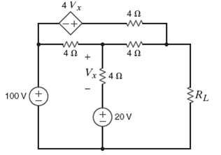
Find RL for maximum power transfer and the maximum power that can be transferred to the load in the circuit in figure.
Find RL for maximum power transfer and the maximum power that can be transferred to the load in the circuit in figure.
Using source transformation, find Io in the circuit in figure.
Find RL for maximum power transfer and the maximum power that can be transferred to the load in figure.
Find the value of RL in the network in figure for maximum power transfer.
Find the value of RL for maximum power transfer and the maximum power that can be transferred to RL in the circuit of figure.
Find the maximum power that can be transferred to RL in the network of figure.
Find the value of RL in for maximum power transfer in the circuit in figure.
In the network of figure, find the value of RL for maximum power transfer. In addition, calculate the power dissipated in RL under these conditions.
Calculate the maximum power that can be transferred to RL in the circuit in figure.
Find RL for maximum power transfer and the maximum power that can be transferred to the load in the circuit in figure.
Using source transformation, find Io in the circuit in figure.
Using PSPICE, find Io in the network in figure.
Using PSPIC, find Vo in the network in figure.
Using PSPICE, find Io in the circuit in figure.
Using PSPICE, find Vo in the network in figure.
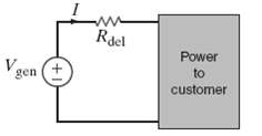
Some young engineers at the local electrical utility are debating ways to lower operating costs. They know that if they can reduce losses, they can lower operating costs. The question is whether they should design for maximum power transfer or maximum efficiency, where efficiency is defined as the
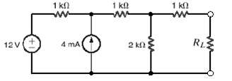
Determine the maximum power than can be delivered to the load RL in the network in figure. a. 2mW b. 10mW c. 4mW d. 8mW
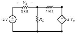
Find the value of the load RL in the network in figure that will achieve maximum power transfer, and determine that value of the maximum power. a. 22.5mW b. 80.4mW c. 64.3mW d. 121.5mW
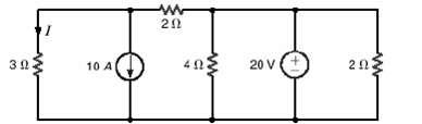
What is the current I in figure? a. 8 A b. ? 4A? c. 0 A d. 4 A
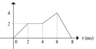
If the voltage across a 10?F capacitor is shown in figure, derive the waveform for the capacitor current.
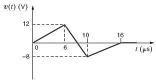
If the voltage across a 100mH inductor is shown in figure, find the waveform for the inductor current.
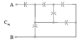
Find the equivalent capacitance of the network in figure at the terminals A-B. All capacitors are 6?F.
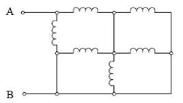
Find the equivalent inductance of the network in figure at the terminals A-B. All inductors are 12mH.
An uncharged 100-μF capacitor is charged by a constant current of 1mA. Find the voltage across the capacitor after 4 s.
A 12-μF capacitor has an accumulated charge of 480 μC. Determine the voltage across the capacitor.
A capacitor has an accumulated charge of 600μC with 5 V across it. What is the value of capacitance?
A 25-μF capacitor initially charged to – 10V is charged by a constant current of 2.5μA. Find the voltage across the capacitor after 2 ½ min.
The energy that is stored in a 25-μF capacitor is w(t) = 12 sin2 377t. Find the current in the capacitor.
A capacitor is charged by a constant current of 2 mA and results in a voltage increase of 12 V in a 10-s interval. What is the value of the capacitance?
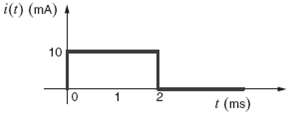
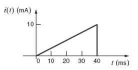
The current in a 100-?F capacitor is shown in figure. Determine the waveform for the voltage across the capacitor if it is initially uncharged.
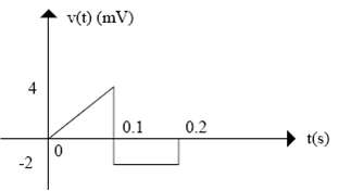
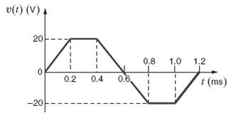
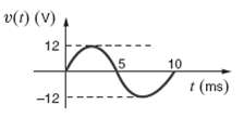
The voltage across a 50-?F capacitor is shown in figure. Determine the current waveform.
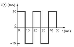
Draw the waveform for the current in a 12-?F capacitor when the capacitor voltage is as described in figure.
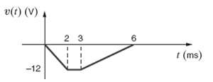
The voltage across a 25-?F capacitor is shown in figure. Determine the current waveform.
The voltage across a 2-F capacitor is given by the waveform in figure. Find the waveform for the current in thecapacitor.
The voltage across a 2-?F capacitor is given by the wave form in figure. Compute the current waveform.
Draw the waveform for the current in a 24-?F capacitor when the capacitor voltage is as described in figure.
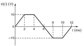
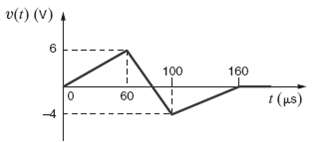
The voltage across a 10-?F capacitor is given by the waveform in figure. Plot the waveform for the capacitor current.
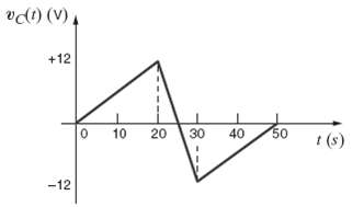
The waveform for the current in a 50-?F capacitor is shown in figure. Determine the waveform for the capacitor voltage.
The waveform for the current in a 50-?F initially uncharged capacitor is shown in figure. Determine the waveform for the capacitor voltage.
Showing 2000 - 2100
of 3459
First
14
15
16
17
18
19
20
21
22
23
24
25
26
27
28
Last
Step by Step Answers