New Semester
Started
Get
50% OFF
Study Help!
--h --m --s
Claim Now
Question Answers
Textbooks
Find textbooks, questions and answers
Oops, something went wrong!
Change your search query and then try again
S
Books
FREE
Study Help
Expert Questions
Accounting
General Management
Mathematics
Finance
Organizational Behaviour
Law
Physics
Operating System
Management Leadership
Sociology
Programming
Marketing
Database
Computer Network
Economics
Textbooks Solutions
Accounting
Managerial Accounting
Management Leadership
Cost Accounting
Statistics
Business Law
Corporate Finance
Finance
Economics
Auditing
Tutors
Online Tutors
Find a Tutor
Hire a Tutor
Become a Tutor
AI Tutor
AI Study Planner
NEW
Sell Books
Search
Search
Sign In
Register
study help
engineering
electrical engineering
Basic Engineering Circuit Analysis 9th Edition J. David Irwin - Solutions
In a balanced three-phase wye-wye system, the source is an abc-sequence set of voltages and Van = 120 < 40o V rms. If the a-phase line current and line impedance are known to be 7.10 < – 10.28o A rms and 0.8 + j1Ω, respectively, find the load impedance.
In a balanced three-phase wye-wye system, the source is 20 + j1Ω. The source has an abc-phase sequence and Van = 120 <0o V rms. If the load voltage is VAN = 111.49 <– 0.2oV rms, determine the magnitude of the line current if the load is suddenly short-circuited.
In a balanced three-phase wye-wye system, the load impedance is 10 + j1Ω. The source has phase sequence abc and the line voltage Vab = 220 < 30o V rms. If the load voltage VAN = 120 < 0o V rms, determine the line impedance.
An abc-phase-sequence three-phase balanced wye-connected 60-Hz source supplies a balanced delta-connected load. The phase impedance in the load consists of a 20-Ω resistor series with a 20-mH inductor, and the phase voltage at the source is Van = 120 < 30o V rms. If the line impedance is zero,
In a three-phase balanced system, a delta-connected source supplies power to a wye-connected load. If the line impedance is 0.2 + j 0.4Ω, the load impedance 3 + j2Ω, and the source phase voltage Vab = 208 < 10o V rms, find the magnitude of the line voltage at the load.
In a balanced three-phase wye-wye system, the source is an abc-sequence set of voltages and Van = 120 < 50o V rms. The load voltage on the a phase is 110 < 50o V rms, and the load impedance is 16 + j20 Ω. Find the line impedance
In a balanced three-phase wye-wye system, the source is an abc-sequence set of voltage and Van = 120 <40o V rms. If the a-phase line current and line impedance are known to be 6 <15o A rms and 1 + j1 Ω, respectively, find the load impedance.
Sketch a phasor representation of a balanced three-phase system containing both phase voltages and line voltages if Van = 100 < 45o V rms. Label all magnitudes and assume and abc-phase sequence. Discuss.
An abc-phase sequence three-phase balanced wye-connected source supplies a balanced delta-connected load. The impedance per phase in the delta load is 12 + j6Ω. The line voltage at the source is Vab = 120 √3 < 40o V rms. If the line impedance is zero, find the line currents in the balanced
In a balanced three-phase delta-wye system, the source has an abc-phase sequence. The line and load impedances are 0.6 + j 0.3 Ω and 12 + j7 Ω, respectively. If the line current IaA = 9.6 < – 20o A rms, determine the phase voltages of the source.
An abc-sequence set of voltages feeds a balanced three-phase wye-wye system. If Van = 440 < 30o V rms, VAN = 413.28 <29.78o V rms, and Z line = 2 + j 1.5 Ω, find the load impedance.
An abc-phase-sequence three-phase balanced wye-connect source supplies a balanced delta-connected load. The impedance per phase of the delta load is 20 + j4Ω. If VAB = 115 <35o V rms, find the line current.
An abc-phase-sequence three-phase balanced wye-connected source supplies power to a balanced delta-connected load. The impedance per phase in the load is 14 + j7Ω. If the source voltage for the a phase is Van = 120<80o V rms and the line impedance is zero, find the phase currents in the
An abc-phase-sequence three-phase balanced wye-connected source supplies a balanced delta-connected load. The impedance per phase of the delta load is 10 + j8Ω. If the line impedance is zero and the line current in the a phase is known to be IaA = 28.10 < – 28.66o A rms, find the load
In a three phase balanced delta-delta system, the source has an abc-phase sequence. The line and load impedances are 0.3 + j0.2 Ω and 9 + j6Ω, respectively. If the load current in the delta is IAB = 15 < 40o A rms, find the phase voltages of the source.
In a balanced three-phase wye-delta system, the source has an abc-phase sequence and Van = 120 < 0o V rms. If the line impedance is zero and the line current IaA = 5 < 20o A rms, find the load impedance per phase in the delta, the source.
A three-phase load impedance consists of a balanced wye in parallel with a balanced delta. What is the equivalent wye load and what is the equivalent delta load if the phase impedances of the wye and delta are 6 + j3 Ω and 15 + j10 Ω, respectively?
In a balanced three-phase delta-delta system, the source has an abc-phase sequence. The phase angle for the source voltage is < Vab = 40o and Iab = 4 <15o A rms. If the total power absorbed by the load is 1400 W, find the load impedance.
In a balanced three-phase system, the abc-phase-sequence source is wye connected and Van = 120 < 20o V rms. The load consists of two balanced wyes with phase impedances of 8 + j2 Ω and 12 + j3 Ω. If the line impedance is zero, find the line currents and the phase current in each load.
In a balanced three-phase system, the source is a balanced wye with an abc-phase sequence and Vab = 215 < 50o V rms. The load is a balanced wye in parallel with a balanced delta. The phase impedance of the wye
In a balanced three-phase system, the source has an abc-phase sequence and is connected in delta. There are two parallel wye-connected loads. The phase impedance of load 1 and load 2 is 4 + j4 Ω and 10 + j4 Ω, respectively. The line impedance connecting the source to the loads is 0.3 + j0.2
An abc-phase sequence balanced three-phase source feeds a balanced load. The system is connected wye-wye and < Van = 0o. The line impedance is 0.5 + j0.2Ω, the load impedance is 16 + j10 Ω, and the total power absorbed by the load is 2000W. Determine the magnitude of the source voltage Van.
A balanced three-phase delta-connected source supplies power to a load consisting of a balanced delta in parallel with a balanced wye. The phase impedance of the delta is 24 + j12 Ω, and the phase impedance of the wye is 12 + j8 Ω. The abc-phase-sequence source voltages are Vab = 440 < 60o V
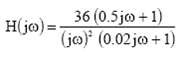
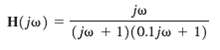
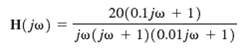
Sketch the bode plot for the following networkfunction
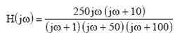
Sketch the bode plot for the following networkfunction
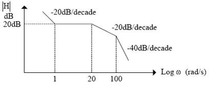
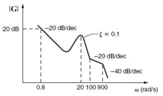
Given the magnitude characteristic for the network function shown in figure, find the expression for H (j?)
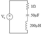
Given the series circuit shown in figure, determine the following parameters: ?0, Q and the BW. If the resistance is changed to 0.1?, what is the impact on these parameters, sketch the frequency characteristic for the two values of R. What conclusion can be drawn from these two characteristics?
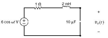
The network in figure operates as a band pass filter. (a) Determine the transfer function for the network, (b) Find the upper and lower cut off frequencies and the band width and (c) Sketch the magnitude characteristic for this transferfunction.
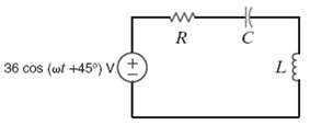
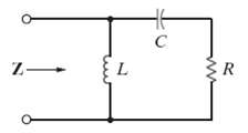
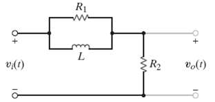
Determine the driving point impedance at the input terminal of the network shown in figure as a function ofs.
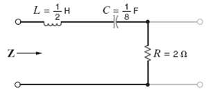
Determine the driving point impedance at the input terminals of the network shown in figure as a function of s.
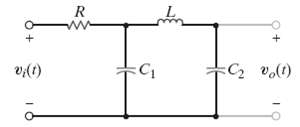
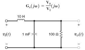
Determine the voltage transfer function Vo(s) / Vi (s) as a function of s for the network shown infigure.
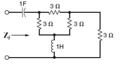
Find the driving point impedance at the input terminals of the circuit in figure as a function of s.
Find the transfer impedance Vo(s) / Is(s) for the network shown infigure.
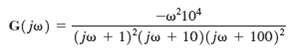
Draw the Bode plot for the network function
Draw the Bode plot for the network function
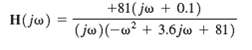
Sketch the magnitude characteristic of the Bode plot for the transfer function
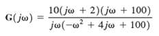
Draw the Bode plot for the network function
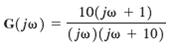
Sketch the magnitude characteristic of the Bode plot for the transfer function
Draw the Bode plot for the network function
Sketch the magnitude characteristic of the Bode plot for the transfer function
Sketch the magnitude characteristic of the Bode plot for the transfer function
Sketch the magnitude characteristic of the Bode plot for the transfer function
Sketch the magnitude characteristic of the Bode plot for the transfer function
Sketch the magnitude characteristic of the Bode plot for the transfer function
Sketch the magnitude characteristic of the Bode plot for the transfer function
Sketch the magnitude characteristic of the Bode plot for the transferfunction
Sketch the magnitude characteristic of the Bode plot for the transfer function
Use MATLAB to generate the Bode plot for the following transfer function over the frequency range from w = 0.01 to 1000 rad/s.
Use MATLAB to generate the BODE plot for the following transfer function over the frequency range from w = 0.1 to 10,000 rad/s.
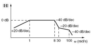
Find H(jw) if its magnitude characteristic is shown infigure.
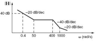
The magnitude characteristic of a band-elimination filter is shown in figure. Determine H(jw)
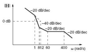
Given the magnitude characteristic in figure find H (jw)
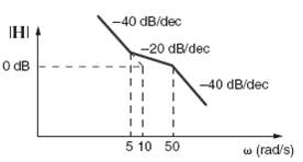
Find H(jw) if its amplitude characteristic is shown infigure.
Find H(jw) if its magnitude characteristic is shown infigure.
Find H(jw) if its amplitude characteristic is shown infigure.
Determine H(jw) if its magnitude characteristic is shown in figure
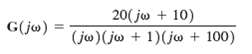
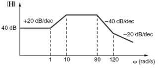
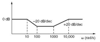
Find G(jw) for the magnitude characteristic shown infigure.
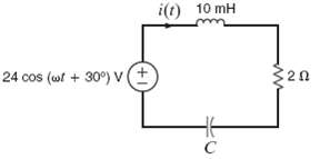
The series RLC circuit in figure is driven by a variable-frequency source. If the resonant frequency of the network is selected as w0 = 1600 rad/s, find the value of C. In addition, compute the current at resonance and at w0/4 and4w0.
A series RLC circuit resonates at 1000 rad/s. If C = 20μF, and it is known that the impedance at resonance is 2.4Ω, compute the value of L, the Q of the circuit, and the band width.
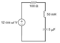
Given the series RLC circuit in figure? (a) Derive the expression for the half-power frequencies, the resonant frequency, the bandwidth, and the quality factor for the transfer characteristic I/Vin in terms of R, L, and C,? (b) Compute the quantities in part (a) if R = 10?, L = 50mH, and C = 10?F.
A series resonant circuit has a Q of 120 and a resonant frequency of 10,000 rad/s. Determine the half-power frequencies and the bandwidth of the circuit.
Given the network in figure, find w0, Q, w max, and|V0|max.
A variable-frequency voltage source drives the network in figure. Determine the resonant frequency, Q, BW, and the average power dissipated by the network atresonance.
In the network in figure, the inductor value is 10mH, and the circuit is driven by a variable-frequency source. If the magnitude of the current at resonance is 12A, w0 = 1000 rad/s, and L = 10mH, find C, Q, and the bandwidth of thecircuit.
A series RLC circuit is driven by a signal generator. The resonant frequency of the network is known to be 1600 rad/s and at the frequency the impedance seen by the signal generator is 5 Ω. If C = 20Μf, find L, Q, and the band width.
A parallel RLC resonant circuit has a resistance of 200 Ω. If it is known that the bandwidth is 80 rad/s and the lower half-power frequency is 800 rad/s, find the values of the parameters L and C.
A parallel RLC resonant circuit with a resonant frequency of 20,000 rad/s has an admittance at resonant of 1mS. If the capacitance of the network is 2μF, find the values of R and L.
A parallel RLC circuit, which is driven by a variable frequency 2-A current source, has the following values: R = 1kΩ, L = 100mH, and C = 10μF. Find the bandwidth of the network, the half-power frequencies, and the voltage across the network at the half-power frequencies.
A parallel RLC circuit, which is driven by a variable frequency 2-A current source, has the following values; R = 1kΩ, L = 400mH, and = 10μF. Find the bandwidth of the network, the half-power frequencies, and the voltage across the network at the half-power frequencies.
Determine the parameters of a parallel resonant circuit that has the following properties; w0 = 2M rad/s, BW = 20rad/s, and an impedance at resonance of 2000 Ω.
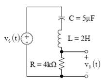
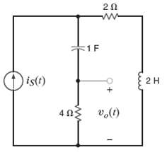
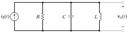
The source in the network in figure is is(t) = cos 1000t + cos 1500t A. R = 200? and C = 500?F. If w0 = 1000 rad/s, find L, Q, and the BW. Compute the output voltage vo(t) and discuss the magnitude of the output voltage at the two input frequencies.
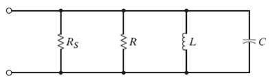
Consider the network in figure. If R = 1k?, L = 20mH, C = 50?F, and Rs = ?, determine the resonant frequency w0 the Q of the network, and the bandwidth of the network what impact does an RS of 10k? have on the quantities determined?
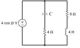
Determine the value of C in the network shown in figure for the circuit to be inresonance.
Determine the equation for the nonzero resonant frequency of the impedance shown infigure.
Determine the new parameters of the network in figure if w new = 104 wold.
Determine the new parameters of the network shown in figure if Z new = 104 Zold.
Given the network in figure, sketch the magnitude characteristic of the transfer function identify the type offilter.
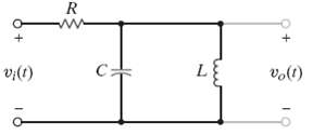
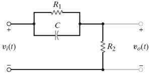
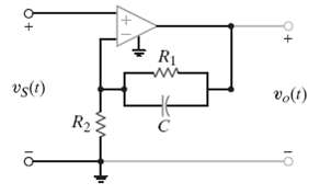
Determine what type of filter the network shown in figure represents by determining the voltage transferfunction.
Determine what type of filter the network shown in figure represents by determining the voltage transferfunction.
Given the network in figure sketch the magnitude characteristic of the transfer function, identify the type offilter.
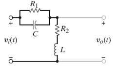
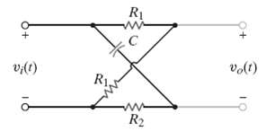
Given the lattice network shown in figure determine what type of filter this network represents by determining the voltage transferfunction.
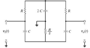
The circuit in figure is a dual T notch filter. It has an advantage over the filter in example in that if contains no inductors, which tend to be bulky and heavy. Derive the transfer function for this filter and verify your work for the component values C = 100nF and R = 1590?
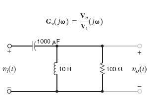
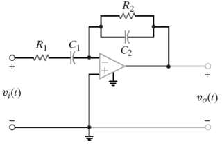
Given the network in figure, find the transfer function Vo/V1 (jw) and determine what type of filter the networkrepresents.
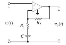
Given the network in figure, and employing the voltage follower analyzed, determine the voltage transfer function and its magnitude characteristic. What type of filter does the networkrepresent?
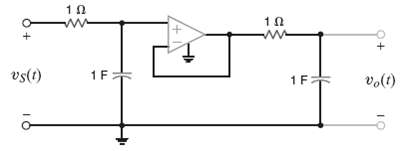
Determine the voltage transfer function and its magnitude characteristic for the network shown in figure and identify the filterproperties.
Repeat problem for the network shown infigure.
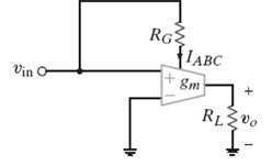
An OTA with a trans-conductance of 1mS is required. A 5-V supply is available, and the sensitivity of gm to IABC is 20.(a) What values of IABC and RG do you recommend?(b) If RG has a tolerance of + 5% what is the possible range of gm in the final circuit?
The OTD and 5-V source described in problem are used to create a Tran-conductance of 2.5mS.(a) What resistor value is required?(b) If the input voltage to the amplifier is vm(t) = 1.5cos (wt) V, what is the output current function?
A particular OTA has a maximum trans-conductance of 5mS with a range of 6 decades.(a) What is the minimum possible trans-conductance?(b) What is the range of IABC?(c) Using a 5-V power sully and resistor to set IABC, what is the range of values for the resistor and the power if consumes?
A circuit is required that can double the frequency of a sinusoidal voltage.(a) If vin(t) = 1 sin (wt) V, show that the multiplier circuit in figure can produce an output that contains a sinusoid at frequency 2 w.(b) We want the magnitude of the double-frequency sinusoid to be 1 V. Determine values
The frequency doublers in problem use a two-quadrant multiplier. (a) What effect does this have on the output signal? (b) The circuit in figure is one solution. Show that vo has a double-frequency term. (c) How would you propose to eliminate the otherterms?
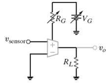
A fluid level sensor, used to measure water level in a reservoir, outputs a voltage directly proportional to fluid level. Unfortunately, the sensitivity of the sensor drifts about 10% over time. Some means for tuning the sensitivity is required. Your engineering team produces the simple OTA circuit
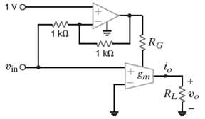
The automatic gain control circuit in figure is used to limit the trans-conductance, io/vin. (a) Find an expression for vo in terms of vin, RG, and RL. (b) Express the asymptotic trans-conductance, io/vin, in terms of RG and RL at vin = 0 and as vin approaches infinity. Given RL and RG values in
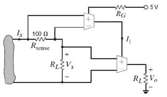
In figure Vx is a dc voltage. The circuit is intended to be a dc wattmeter where the output voltage value equals the power consumed by RL in watts. (a) The Gm ? I ABC sensitivity is 20 S/A. Find RG such that Ix/I1 = 104. (b) Choose RL such that 1 V at Vo corresponds to 1 W dissipated in RL.
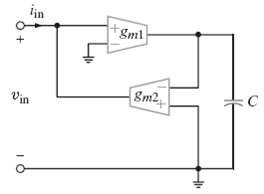
Prove that the circuit in figure is a simulated inductor. Find the inductance in terms of C, gm1, and gm2.
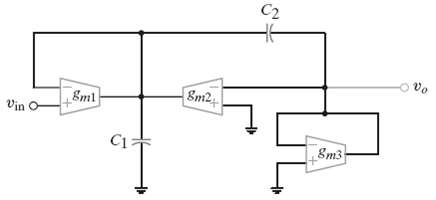
Fin d the transfer function of the OTA filter in figure. Express w0 and Q in terms of the capacitances and trans-conductances. What kind of filter isit?
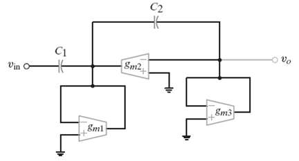
Find the transfer function of the OTA filter in figure. Express w0 and Q in terms of the capacitance's and trans-conductance?s what kind of filter is it?
Design a low-pass filter with a cutoff frequency between 15 and 16 kHz.
Design a low-pass filter using one resistor and one capacitor that will produce a 4.24-volt output at 159 Hz when 6 volts at 159 Hz are applied at the input.
Design a high-pass filter with a half-power frequency between 159 and 161 kHz.
Showing 2500 - 2600
of 3459
First
19
20
21
22
23
24
25
26
27
28
29
30
31
32
33
Last
Step by Step Answers