New Semester
Started
Get
50% OFF
Study Help!
--h --m --s
Claim Now
Question Answers
Textbooks
Find textbooks, questions and answers
Oops, something went wrong!
Change your search query and then try again
S
Books
FREE
Study Help
Expert Questions
Accounting
General Management
Mathematics
Finance
Organizational Behaviour
Law
Physics
Operating System
Management Leadership
Sociology
Programming
Marketing
Database
Computer Network
Economics
Textbooks Solutions
Accounting
Managerial Accounting
Management Leadership
Cost Accounting
Statistics
Business Law
Corporate Finance
Finance
Economics
Auditing
Tutors
Online Tutors
Find a Tutor
Hire a Tutor
Become a Tutor
AI Tutor
AI Study Planner
NEW
Sell Books
Search
Search
Sign In
Register
study help
engineering
introduction mechanical engineering
Mechanical Vibrations Theory And Applications 1st Edition S. GRAHAM KELLY - Solutions
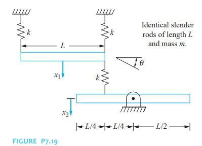
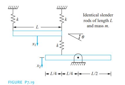
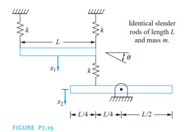
Determine the potential energy of the system at an arbitrary instant for the systems of Figure P7.19. Put the potential energy in a quadratic form. Use the quadratic form to determine the stiffness matrix for the system. x1 FIGURE P7.19 L 2 Identical slender rods of length L and mass m. L/4 L/42/2
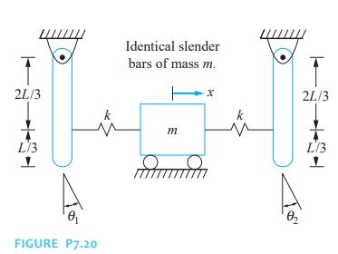
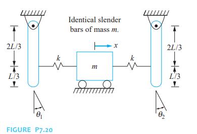
Determine the potential energy of the system at an arbitrary instant for the systems of Figure P7.20. Put the potential energy in a quadratic form. Use the quadratic form to determine the stiffness matrix for the system. Identical slender bars of mass m. 2L/3 L/3 k m FIGURE P7.20 2L/3 L/3
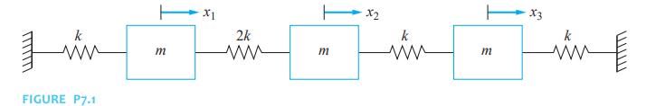
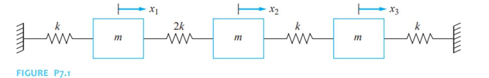
Derive the stiffness matrix for the systems of Figure P7.1 using the indicated generalized coordinates and stiffness influence coefficients. k x1 2k x2 |--- ww m m ww m X3 ww FIGURE P7.1
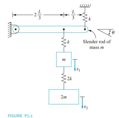
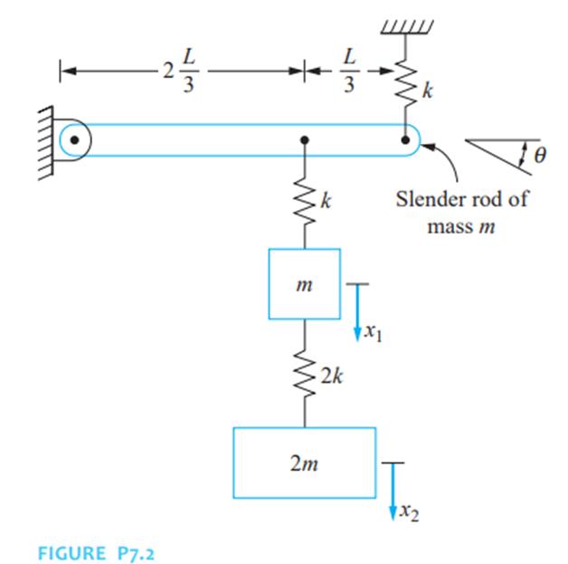
Derive the stiffness matrix for the systems of Figure P7.2 using the indicated generalized coordinates and stiffness influence coefficients. -25- FIGURE P7.2 m 2m k k Slender rod of mass m 2k x1 1x2
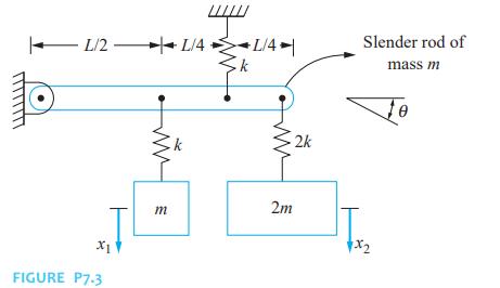
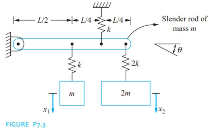
Derive the stiffness matrix for the systems of Figure P7.3 using the indicated generalized coordinates and stiffness influence coefficients. L/2 L/2 L/4- L/4 Slender rod of x1 FIGURE P7-3 mass m 2k Te m 2m x2
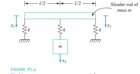
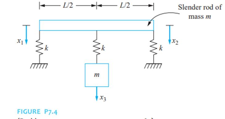
Derive the stiffness matrix for the systems of Figure P7.4 using the indicated generalized coordinates and stiffness influence coefficients. x1 FIGURE P7.4 - L/2- L/2 m X3 x2 Slender rod of mass m
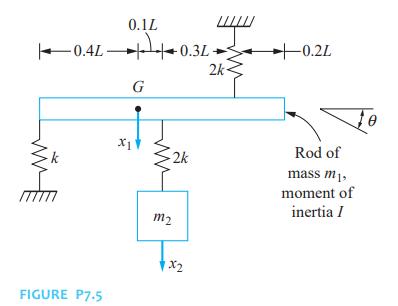
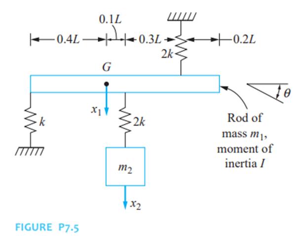
Derive the stiffness matrix for the systems of Figure P7.5 using the indicated generalized coordinates and stiffness influence coefficients. 0.1L 0.4L 0.3L G X1 2k m2 FIGURE P7.5 x2 2k -0.2L Rod of mass m, moment of inertia I
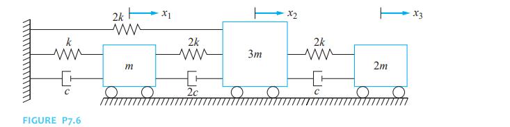
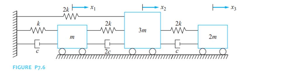
Derive the stiffness matrix for the systems of Figure P7.6 using the indicated generalized coordinates and stiffness influence coefficients. www 2k ww x1 2k ww C FIGURE P7.6 m 2c x2 2k 3m 2m X3
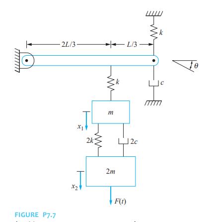
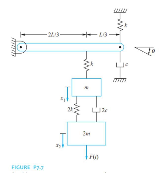
Derive the stiffness matrix for the systems of Figure P7.7 using the indicated generalized coordinates and stiffness influence coefficients. -2L/3- L/3- FIGURE P7-7 2k m x2 2m F(t) 2c Te
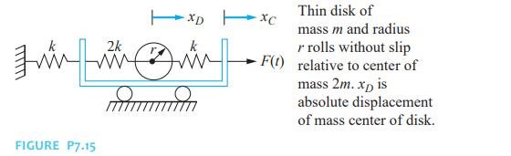
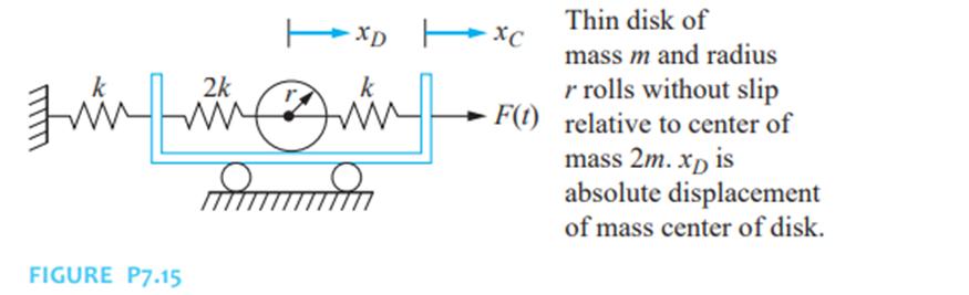
Derive the stiffness matrix for the systems of Figure P7.15 using the indicated generalized coordinates and stiffness influence coefficients. FIGURE P7.15 2k xDxc mum Thin disk of mass m and radius r rolls without slip F(t) relative to center of mass 2m. xD is absolute displacement of mass center
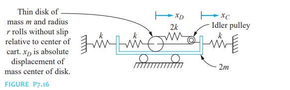
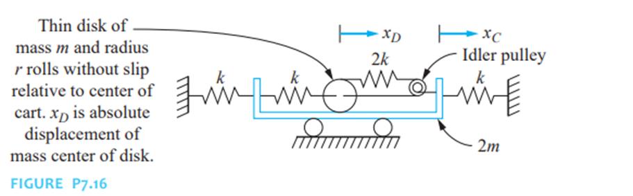
Derive the stiffness matrix for the systems of Figure P7.16 using the indicated generalized coordinates and stiffness influence coefficients. Thin disk of mass m and radius r rolls without slip relative to center of cart. xp is absolute displacement of mass center of disk. FIGURE P7.16 xc XD 2k
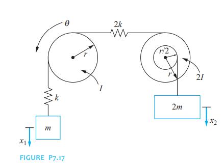
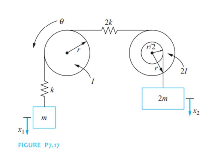
Derive the stiffness matrix for the systems of Figure P7.17 using the indicated generalized coordinates and stiffness influence coefficients. X1 m FIGURE P7.17 2k ww r/2 2m 21 TxX2
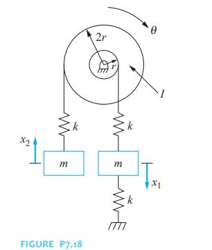
Derive the stiffness matrix for the systems of Figure P7.18 using the indicated generalized coordinates and stiffness influence coefficients. x2 2r 17 m m FIGURE P7.18 k x1
Derive the stiffness matrix for the systems of Figure P7.19 using the indicated generalized coordinates and stiffness influence coefficients. k L x1 Identical slender rods of length L and mass m. FIGURE P7.19 x2 | L/4 | L/4 | L/2
Derive the stiffness matrix for the systems of Figure P7.20 using the indicated generalized coordinates and stiffness influence coefficients. 2L/3 Identical slender bars of mass m. L/3 FIGURE P7.20 M m 2L/3 L/3
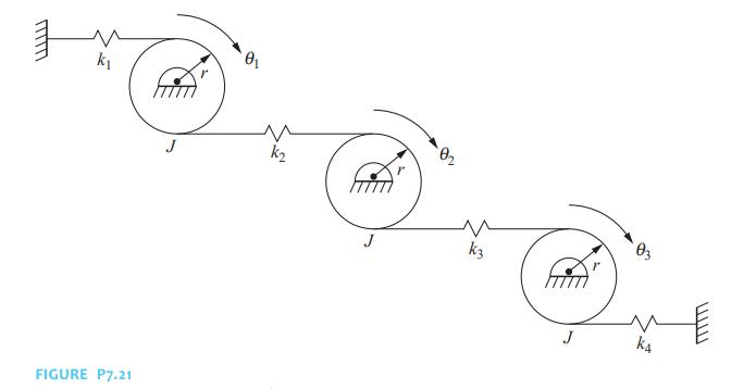
Derive the stiffness matrix for the systems of Figure P7.21 using the indicated generalized coordinates and stiffness influence coefficients. FIGURE P7.21 k k3 J k4
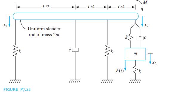
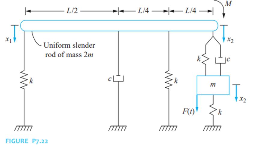
Derive the stiffness matrix for the systems of Figure P7.22 using the indicated generalized coordinates and stiffness influence coefficients. M L/2 L/4 L/4 x1 Uniform slender rod of mass 2m www FIGURE P7.22 F(1) k x2 m | Tx x2
Determine the flexibility matrix for the systems of Figure P7.1 using the indicated generalized coordinates and flexibility influence coefficients. k x2 2k k X3 1m 5m 5m5 ww ww k FIGURE P7.1
Determine the flexibility matrix for the systems of Figure P7.2 using the indicated generalized coordinates and flexibility influence coefficients. FIGURE P7.2 ++ L 23 k k Slender rod of mass m w m 12 www 2k 26 x1 2m 1x2
Determine the flexibility matrix for the systems of Figure P7.3 using the indicated generalized coordinates and flexibility influence coefficients. x1 FIGURE P7.3 L/4| Slender rod of k mass m 2k Te m 2m x2
Determine the flexibility matrix for the systems of Figure P7.4 using the indicated generalized coordinates and flexibility influence coefficients. x1 L/2 L/2 Slender rod of m FIGURE P7.4 x3 k x2 mass m
Determine the flexibility matrix for the systems of Figure P7.5 using the indicated generalized coordinates and flexibility influence coefficients. 0.1L +24+0.34. 0.4 0.3L G FIGURE P7.5 x1 2k m2 x2 0.2L 2k- Rod of mass m, moment of inertia /
Determine the flexibility matrix for the systems of Figure P7.6 using the indicated generalized coordinates and flexibility influence coefficients. FIGURE P7.6 2k ww x1 2k m ww 2c x2 2k 3m ww 2m C X3
Determine the flexibility matrix for the systems of Figure P7.7 using the indicated generalized coordinates and flexibility influence coefficients. 2L/3. L/3- FIGURE P7-7 www m www 2k J2c x2 2m F(t) Te
Determine the flexibility matrix for the systems of Figure P7.15 using the indicated generalized coordinates and flexibility influence coefficients. 2k TxD xD xc Thin disk of FIGURE P7.15 mum - F(t) mass m and radius r rolls without slip relative to center of mass 2m. xD is XD absolute
Determine the flexibility matrix for the systems of Figure P7.16 using the indicated generalized coordinates and flexibility influence coefficients. Thin disk of mass m and radius r rolls without slip relative to center of cart. xD is absolute displacement of mass center of disk. FIGURE P7.16 XC
Determine the flexibility matrix for the systems of Figure P7.17 using the indicated generalized coordinates and flexibility influence coefficients. 2k www r/2 k 2m m 17 x1 FIGURE P7.17 21 x2
Determine the flexibility matrix for the systems of Figure P7.18 using the indicated generalized coordinates and flexibility influence coefficients. 2r 0 x2 www k www m x1 12 12 m k WE FIGURE P7.18
Determine the flexibility matrix for the systems of Figure P7.19 using the indicated generalized coordinates and flexibility influence coefficients. L XIV www Identical slender rods of length L and mass m. R FIGURE P7.19 x21 | L/4 L/4 | 1/2 |
Determine the flexibility matrix for the systems of Figure P7.20 using the indicated generalized coordinates and flexibility influence coefficients. 2L/3 Identical slender bars of mass m. L/3 mu FIGURE P7.20 m x k 2L/3 L/3
Determine the flexibility matrix for the systems of Figure P7.21 using the indicated generalized coordinates and flexibility influence coefficients. k FIGURE P7.21 k2 03 J k4 www
Determine the flexibility matrix for the systems of Figure P7.22 using the indicated generalized coordinates and flexibility influence coefficients. M L/2 | L/4 L/4 X1 Uniform slender rod of mass 2m FIGURE P7.22 TTTTTT www F(t) 1x2 m 12 k x2
Determine the mass matrix for the systems of Figure P7.1 using the indicated generalized coordinates and flexibility influence coefficients. k x2 2k k X3 1m 5m 5m5 ww ww k FIGURE P7.1
Determine the mass matrix for the systems of Figure P7.2 using the indicated generalized coordinates and flexibility influence coefficients. FIGURE P7.2 ++ L 23 k k Slender rod of mass m w m 12 www 2k 26 x1 2m 1x2
Determine the mass matrix for the systems of Figure P7.3 using the indicated generalized coordinates and flexibility influence coefficients. x1 FIGURE P7.3 L/4| Slender rod of k mass m 2k Te m 2m x2
Determine the mass matrix for the systems of Figure P7.4 using the indicated generalized coordinates and flexibility influence coefficients. x1 L/2 L/2 Slender rod of m FIGURE P7.4 x3 k x2 mass m
Determine the mass matrix for the systems of Figure P7.5 using the indicated generalized coordinates and flexibility influence coefficients. 0.1L +24+0.34. 0.4 0.3L G FIGURE P7.5 x1 2k m2 x2 0.2L 2k- Rod of mass m, moment of inertia /
Determine the mass matrix for the systems of Figure P7.6 using the indicated generalized coordinates and flexibility influence coefficients. FIGURE P7.6 2k ww x1 2k m ww 2c x2 2k 3m ww 2m C X3
Determine the mass matrix for the systems of Figure P7.7 using the indicated generalized coordinates and flexibility influence coefficients. 2L/3. L/3- FIGURE P7-7 www m www 2k J2c x2 2m F(t) Te
Determine the mass matrix for the systems of Figure P7.15 using the indicated generalized coordinates and flexibility influence coefficients. 2k TxD xD xc Thin disk of FIGURE P7.15 mum - F(t) mass m and radius r rolls without slip relative to center of mass 2m. xD is XD absolute displacement of
Determine the mass matrix for the systems of Figure P7.16 using the indicated generalized coordinates and flexibility influence coefficients. Thin disk of mass m and radius r rolls without slip relative to center of cart. xD is absolute displacement of mass center of disk. FIGURE P7.16 XC Idler
Determine the mass matrix for the systems of Figure P7.17 using the indicated generalized coordinates and flexibility influence coefficients. 2k www r/2 k 2m m 17 x1 FIGURE P7.17 21 x2
Determine the mass matrix for the systems of Figure P7.18 using the indicated generalized coordinates and flexibility influence coefficients. 2r 0 x2 www k www m x1 12 12 m k WE FIGURE P7.18
Determine the mass matrix for the systems of Figure P7.19 using the indicated generalized coordinates and flexibility influence coefficients. L XIV www Identical slender rods of length L and mass m. R FIGURE P7.19 x21 | L/4 L/4 | 1/2 |
Determine the mass matrix for the systems of Figure P7.20 using the indicated generalized coordinates and flexibility influence coefficients. 2L/3 Identical slender bars of mass m. L/3 mu FIGURE P7.20 m x k 2L/3 L/3
Determine the mass matrix for the systems of Figure P7.21 using the indicated generalized coordinates and flexibility influence coefficients. k FIGURE P7.21 k2 03 J k4 www
Determine the mass matrix for the systems of Figure P7.22 using the indicated generalized coordinates and flexibility influence coefficients. M L/2 | L/4 L/4 X1 Uniform slender rod of mass 2m FIGURE P7.22 TTTTTT www F(t) 1x2 m 12 k x2
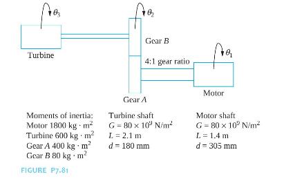
Derive the differential equations governing the torsional oscillations of the turbomotor of Figure P7.81. The motor operates at \(800 \mathrm{rpm}\) and the turbine shaft turns at \(3200 \mathrm{rpm}\). Gear B Turbine 4:1 gear ratio Moments of inertia: Motor 1800 kg. m Turbine 600 kg m2 Gear A 400
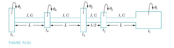
Derive the differential equations governing the torsional oscillations of the system of Figure P7.82. 03 04 J, G J, G J, G J, G L L 1/2+ L 12 13 FIGURE P7.82
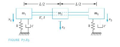
A rotor of mass \(m\) is mounted on an elastic shaft with journal bearings at both ends. A three degree-of-freedom model of the system is shown in Figure P7.83. Each journal bearing is modeled as a spring in parallel with a viscous damper. Drive the differential equations governing the transverse
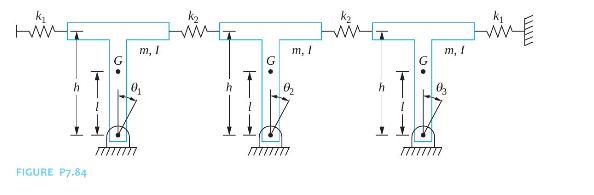
A three degree-of-freedom model of a railroad bridge is shown in Figure P7.84. The bridge is composed of three rigid spans. Each span is pinned at its base. Using the angular displacements of the spans as generalized coordinates, derive the differential equations governing the motion of the bridge.
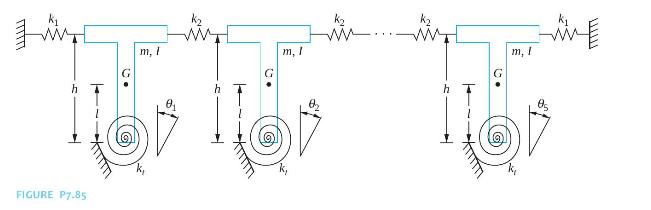
A five-degree of model of a railroad bridge is shown in Figure P7.85. The bridge is composed of five rigid spans. The connection between each span and its base is modeled as a torsional spring. Using the angular displacements of the spans as the generalized coordinates, derive the differential
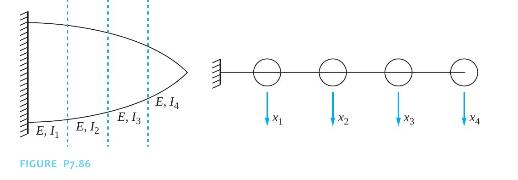
A four degree-of-freedom model of an aircraft wing is shown in Figure P7.86.Derive the flexibility matrix for the model. E. 14 E, E. 12 E, L FIGURE P7.86
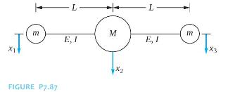
Figure P7.87 illustrates a three degree-of-freedom model of an aircraft. A rigid fuselage is attached to two thin flexible wings. An engine is attached to each wing, but the wings themselves are of negligible mass. Derive the differential equations governing the motion of the system. L L m M m E, I
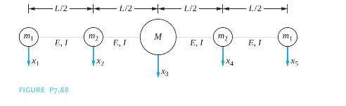
An airplane is modeled as two flexible wings attached to a rigid fuselage (Figure P7.88). Use two degrees of freedom to model each wing and derive the differential equations governing the motion of the five degree-of-freedom system. 1/2 1/2 L/2 L/2- mi m M my m E, I E, I E, I E, J X4 FIGURE P7.88
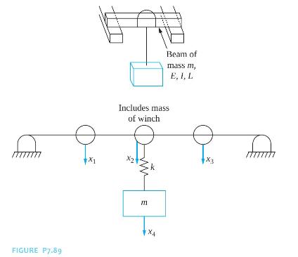
A drum of mass \(m\) is being hoisted by an overhead crane as illustrated in Figure P7.89. The crane is modeled as a simply supported beam with a winch at its midspan. The cable connecting the crane to the drum is of stiffness \(k\). Derive the differential equations governing the motion of the
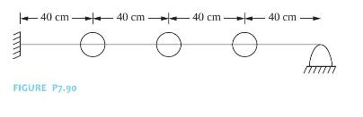
The beams shown in Figures P7.90 are made of an elastic material of elastic modulus \(210 \times 10^{9} \mathrm{~N} / \mathrm{m}^{2}\) and have a cross-sectional moment of inertia \(1.3 \times 10^{-5} \mathrm{~m}^{4}\). Determine the flexibility matrix when a three degree-of-freedom model is used
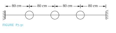
The beams shown in Figures P7.91 are made of an elastic material of elastic modulus \(210 \times 10^{9} \mathrm{~N} / \mathrm{m}^{2}\) and have a cross-sectional moment of inertia \(1.3 \times 10^{-5} \mathrm{~m}^{4}\). Determine the flexibility matrix when a three degree-of-freedom model is used
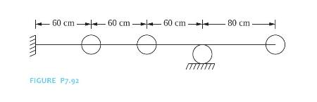
The beams shown in Figures P7.92 are made of an elastic material of elastic modulus \(210 \times 10^{9} \mathrm{~N} / \mathrm{m}^{2}\) and have a cross-sectional moment of inertia \(1.3 \times 10^{-5} \mathrm{~m}^{4}\). Determine the flexibility matrix when a three degree-of-freedom model is used
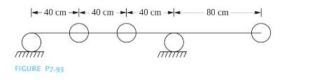
The beams shown in Figures P7.93 are made of an elastic material of elastic modulus \(210 \times 10^{9} \mathrm{~N} / \mathrm{m}^{2}\) and have a cross-sectional moment of inertia \(1.3 \times 10^{-5} \mathrm{~m}^{4}\). Determine the flexibility matrix when a three degree-of-freedom model is used
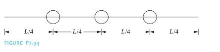
Determine the stiffness matrix for the three degree-of-freedom model of the freefree beam of Figure P7.94. L/4 FIGURE P7.94 L/4. L/4 - Li4
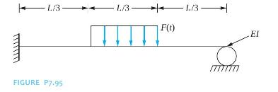
Using a two degree-of-freedom model, derive the differential equations governing the forced vibration of the system of Figure P7.95. L/3 L/3- L/3 1/3- F(t) FIGURE P7.95 EI
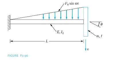
Use a two degree-of-freedom model to derive the differential equations governing the motion of the system of Figure P7.96. A thin disk of mass moment of inertia \(I_{D}\) is attached to the end of the fixed-free beam. Use \(x\), the vertical displacement of the disk, and \(\theta\), the slope of
The natural frequencies of a MDOF system are the eigenvalues of \(\mathbf{M}^{-1} \mathbf{K}\).Indicate whether the statement presented is true or false. If true, state why. If false, rewrite the statement to make it true.
An \(n\) degree-of-freedom system has \(n+1\) natural frequencies.Indicate whether the statement presented is true or false. If true, state why. If false, rewrite the statement to make it true.
The mode-shape vector is the solution of \(\left(\mathbf{A M}-\frac{1}{\omega^{2}} \mathbf{I}\right) \mathbf{X}=0\).Indicate whether the statement presented is true or false. If true, state why. If false, rewrite the statement to make it true.
A node for a mode is a particle that has zero displacement when the vibrations are solely at that frequency.Indicate whether the statement presented is true or false. If true, state why. If false, rewrite the statement to make it true.
The mode-shape vectors are orthogonal with respect to the standard inner product. That is, \(\mathbf{X}_{j}^{T} \mathbf{X}_{i}=0\).Indicate whether the statement presented is true or false. If true, state why. If false, rewrite the statement to make it true.
The mode-shape vector corresponding to a natural frequency \(\omega\) for a MDOF system is unique.Indicate whether the statement presented is true or false. If true, state why. If false, rewrite the statement to make it true.
The eigenvectors are normalized by requiring that the kinetic-energy inner product of a mode-shape vector with itself is one.Indicate whether the statement presented is true or false. If true, state why. If false, rewrite the statement to make it true.
The modal matrix is the transpose of the matrix whose columns are the normalized mode-shape vectors.Indicate whether the statement presented is true or false. If true, state why. If false, rewrite the statement to make it true.
Proportional damping occurs when the damping matrix is proportional to the flexibility matrix.Indicate whether the statement presented is true or false. If true, state why. If false, rewrite the statement to make it true.
The natural frequencies of a \(n \mathrm{DOF}\) system are the roots of a \(n\) th-order polynomial.Indicate whether the statement presented is true or false. If true, state why. If false, rewrite the statement to make it true.
\(\quad \mathbf{P}^{\mathbf{T}} \mathbf{M P}=\mathbf{I}\) where \(\mathbf{P}\) is the modal matrix and \(\mathbf{I}\) is the identity matrix.Indicate whether the statement presented is true or false. If true, state why. If false, rewrite the statement to make it true.
If \(\mathbf{X}_{i}\) is a normalized mode shape corresponding to a natural frequency \(\omega_{i}\), then \(\left(\mathbf{X}_{i}, \mathbf{X}_{i}\right)_{K}=\omega_{i}^{2}\).Indicate whether the statement presented is true or false. If true, state why. If false, rewrite the statement to make it
The lowest natural frequency when \(\operatorname{det} \mathbf{K}=0\) is zero.Indicate whether the statement presented is true or false. If true, state why. If false, rewrite the statement to make it true.
The flexibility matrix does not exist for an unrestrained system.Indicate whether the statement presented is true or false. If true, state why. If false, rewrite the statement to make it true.
Rayleigh's quotient can be applied to obtain a lower-bound on the lowest natural frequency.Indicate whether the statement presented is true or false. If true, state why. If false, rewrite the statement to make it true.
The damping ratio for a proportionally damped system where the proportional damping is proportional to the stiffness matrix is inversely proportional to the natural frequency.Indicate whether the statement presented is true or false. If true, state why. If false, rewrite the statement to make it
Matrix iteration is a method used to determine natural frequencies of a MDOF system iteratively.Indicate whether the statement presented is true or false. If true, state why. If false, rewrite the statement to make it true.
If [ 12\(]^{T}\) is a mode-shape vector corresponding to a natural frequency of \(100 \mathrm{rad} / \mathrm{s}\) for a two non-degenerate system, then \([26]^{T}\) is also a mode-shape vector corresponding to \(100 \mathrm{rad} / \mathrm{s}\).Indicate whether the statement presented is true or
What is the normal mode solution?
What is the dynamical matrix?
The natural frequencies of an \(n \mathrm{DOF}\) system are the of the eigenvalues of \(\mathbf{A M}\).
The natural frequencies and mode-shape vectors for a \(n \mathrm{DOF}\) system have been determined. How is the free response of the system determined?
What is the name for the mode corresponding to a natural frequency equal to zero?
How many linearly independent mode-shape vectors correspond to a natural frequency that is a double root of the characteristic equation?
Define the potential-energy scalar product.
What does the term "kinetic energy" refer to in the kinetic-energy scalar product?
How is the property of commutivity of scalar products satisfied for the kineticenergy scalar product?
What is meant by mode-shape orthogonality?
What is a normalized mode-shape vector?
Define Rayleigh's quotient for an arbitrary \(n\)-dimensional vector.
When is Rayleigh's quotient stationary?
Why is the modal matrix nonsingular?
State the expansion theorem.
What are the principal coordinates for an undamped, linear MDOF system?
How is matrix iteration used to approximate the lowest natural frequency of a MDOF system?
What is the modal damping ratio?
Why can the principal coordinates of an undamped system be used as principal coordinates for a viscously damped system with proportional damping?
Showing 1000 - 1100
of 4547
First
4
5
6
7
8
9
10
11
12
13
14
15
16
17
18
Last
Step by Step Answers