New Semester
Started
Get
50% OFF
Study Help!
--h --m --s
Claim Now
Question Answers
Textbooks
Find textbooks, questions and answers
Oops, something went wrong!
Change your search query and then try again
S
Books
FREE
Study Help
Expert Questions
Accounting
General Management
Mathematics
Finance
Organizational Behaviour
Law
Physics
Operating System
Management Leadership
Sociology
Programming
Marketing
Database
Computer Network
Economics
Textbooks Solutions
Accounting
Managerial Accounting
Management Leadership
Cost Accounting
Statistics
Business Law
Corporate Finance
Finance
Economics
Auditing
Tutors
Online Tutors
Find a Tutor
Hire a Tutor
Become a Tutor
AI Tutor
AI Study Planner
NEW
Sell Books
Search
Search
Sign In
Register
study help
engineering
introduction mechanical engineering
Principles Of Mechanical Engineering 1st Edition Sadhu Singh - Solutions
The state of stress at a point is given by:\[ \sigma_{x}=140 \mathrm{MPa}, \sigma_{y}=100 \mathrm{MPa}, \tau_{x y}=60 \mathrm{MPa} \]Calculate (a) the principal stresses, and (b) the principal planes.
The state of stress at a point is given by\[ \sigma_{x}=300 \mathrm{MPa}, \sigma_{\mathrm{y}}=-200 \mathrm{MPa}, \tau_{x y}=100 \mathrm{MPa}(\mathrm{cw}) \]Draw the Mohr's circle and determine (a) the principal stresses and principal planes, (b) normal and shear stresses on a plane inclined at
The state of stress at a point is given by:\[ \sigma_{x}=-150 \mathrm{MPa}, \sigma_{y} 250 \mathrm{MPa}, \tau_{x y}=100 \mathrm{MPa}(\mathrm{ccw}) \]Draw the Mohr's circle and determine (a) the principal stresses and principal planes, (b) the maximum shear stress and its planes, and (c) draw the
A rectangular block \(250 \mathrm{~mm} \times 100 \mathrm{~mm} \times 50 \mathrm{~mm}\) is subjected to the following state of stress.\[ \sigma_{x}=100 \mathrm{MPa}, \sigma_{y}=-60 \mathrm{MPa}, \sigma_{z}=80 \mathrm{MPa} \]If \(\mathrm{v}=0.25\) and \(E=200 \mathrm{GPa}\), determine its change
A square bar of \(20 \mathrm{~mm}\) side and \(200 \mathrm{~mm}\) long is subjected to a compressive load of 200 \(\mathrm{KN}\) applied in the direction of its length. If all the strains in the other two directions are prevented, determine the contraction in length.
A bar is subjected to the following stresses\[ \sigma_{x}=50 \mathrm{MPa}, \sigma_{y}=-40 \mathrm{MPa}, \sigma_{z}=70 \mathrm{MPa} \]If \(v=0.25\) and \(E=200 \mathrm{GPa}\), calculate (a) the principal strains, (b) volumetric strain, (c) shear modulus, and (d) bulk modulus.
The following strains were measured on pressures vessel\[ \varepsilon_{x}=500 \times 10^{-6}, \varepsilon_{y}=-100 \times 10^{-6} \]and at \(45^{\circ}\) with \(x\)-axis, \(\varepsilon_{z}=-200 \times 10^{-6}\) Calculate (a) the principal strains, and (b) principal stresses.Take \(v=0.3\) and
The state of strain at a point is given by\[ \varepsilon_{x}=400 \times 10^{-6}, \varepsilon_{y}=-200 \times 10^{-6}, \gamma_{x y}=250 \times 10^{-6} \]Calculate (a) the principal strains, and (b) principal strains.
The principal strains at a point are given by\[ \varepsilon_{1}=800 \times 10^{-6}, \varepsilon_{2}=-600 \times 10^{-6}, \varepsilon_{3}=400 \times 10^{-6} \]If \(v=0.25\) and \(\mathrm{E}=200 \mathrm{GPa}\), calculate the principal stresses.
A circle \(50 \mathrm{~mm}\) in diameter is scribed on a mild steel plate before it is subjected to the following state of stress:\(\sigma_{x}=200 \mathrm{MPa}, \sigma_{y}=100 \mathrm{MPa}=\tau x y=80 \mathrm{MPa}\)Calculate the length of the major and minor axes of the ellipse after deformation.
Define a beam.
Define sagging and hogging bending moment.
Define point of inflation.
Define point of ontraflexure.
Explain the sign convention for shear force.
What is the solution ship between load, shear force and bending moment?
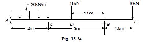
Draw the shear force and bending moment diagrams for the simply supported beam loaded as show in Fig. 15.34. 20kN/m A 2m 15kN 1.5m D 3m Fig. 15.34 10kN E B 1.5m-
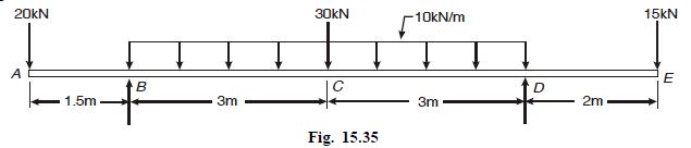
Draw the B.M. and S.F. diagrams for the simply supported beam loaded as shown in Fig 15.35 . 20kN A 1.5m B 3m 30kN -10kN/m + Fig. 15.35 3m D 15kN E 2m
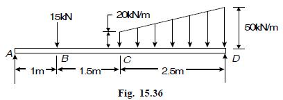
Draw the B.M. and S.F. diagrams for the simply supported beam loaded as shown in Fig. 15.36. 15kN 20kN/m 1m B 1.5m Fig. 15.36 2.5m D 50kN/m
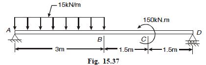
Draw the B.M. and S.F. diagrams for the beam loaded as shown in Fig. 15.37 . A 15kN/m B 3m Fig. 15.37 1.5m 150kN.m 1.5m D
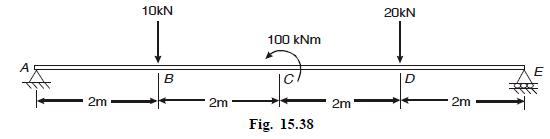
Draw the B.M. and S.F. diagrams for the beam shown in Fig. 15.38 . 10kN 100 kNm 20kN 2m B 2m Fig. 15.38 2m D 2m E
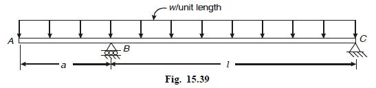
Calculate the value of ‘a’ so that maximum positive bending moment is equal to the maximum negative bending moment for the beam shown in Fig. 15.39 B w/unit length Fig. 15.39
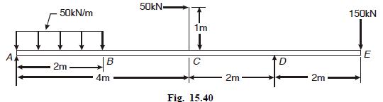
Draw the B.M. and S.F. diagrams for the beam shown in Fig. 15.40. 50kN/m 2m 4m B 50kN T 1m Fig. 15.40 2m D 2m 150kN E
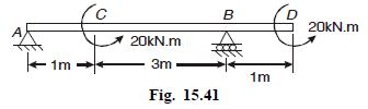
Draw the B.M. and S.F. diagrams for the beam shown in Fig 15.41 20kN.m B 11 1m 3m 1m Fig. 15.41 20kN.m
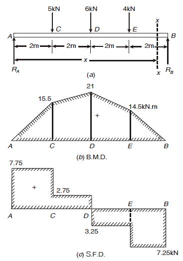
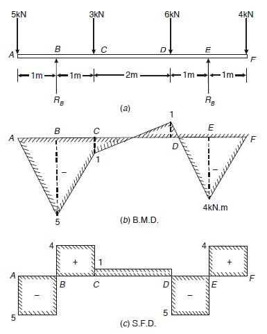
Draw the bending moment and shear force diagrams for the simply supported beam loaded as shown in Fig. 15.16 (a). RA 2m 5kN 6kN 4kN to 2m 2m 15.5 (a) 21 A C 7.75 + 2.75 + D (b) B.M.D. A C D 3.25 E 2m+ 14.5kN.m B I x RB E B B (c) S.F.D. 7.25kN
Drawn the bending moment and shear force diagrams for the simply supported beam shown in Fig 15.17 (a).
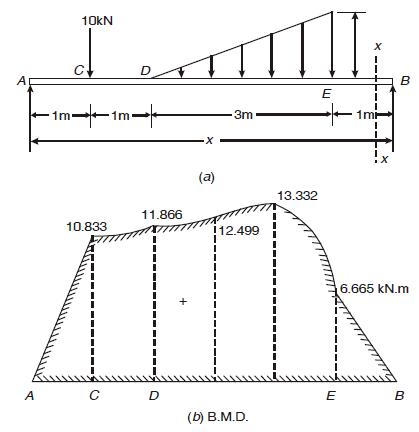
Draw the B.M. and S.F. diagrams for the simply supported beam shown in Fig. 15.18 (a). A C 10kN D 1m- |1m| x (a) 3m E 10.833 11.866 !12.499 13.332 x 1mm B 6.665 kN.m A C D E B (b) B.M.D.
Drawn the B.M. and S.F. diagrams for the cantilever beam shown in Fig 15.19 (a). x -5kN/m 3m x (a) 2m 10kN B
Draw the B.M. and S.F. diagrams for the cantilever beam shown in Fig. 15.20 (a) 5kN T 5kN A 1m C 1m-> D 3m B (a)
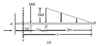
Draw the B.M. and S.F. diagrams for the overhanging beam shown in Fig. 15.21 (a) 5kN 3kN B C 1m- 1m- 2m RB B A 5 5 1 (a) (b) B.M.D. 6kN 4KN D E F D 1m - RB E 4kN.m 'F B C D (c) S.F.D. 10 5
Draw the B.M and S.F. diagrams for the beam shown in Fig. 15.22 (a)
Draw the B.M. and S.F. diagrams for the beam shown in Fig 15.23 (a).
Draw the B.M. and S.F. diagrams for the beam shown in Fig 15.24 (a).
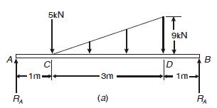
Draw the B.M. and S.F. diagrams for the beam shown in Fig. 15.25 (a). A RA 5kN 1m 3m (a) 9kN D 1m B RA
A beam is loaded as shown in Fig 15.26 (a). Draw the B.M. and S.F.diagrams.
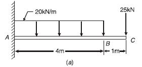
A cantilever beam is loaded as shown in Fig 15.27(a). Draw the B.M. and S.F. diagrams. A 20kN/m 4m (a) B 25kN C 1m-
A cantilever beam is loaded as shown in Fig. 15.28 (a). Draw the B.M. and S.F. diagrams. 15kN 10kN A 5m (a) B 2m.
Draw the B.M and S.F. Diagrams for the beam loaded as shown in Fig 15.29.
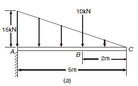
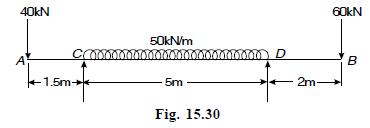
Draw S.F. and B.M. Diagrams for the beam shown in Fig 15.30 Find the position and magnitude of bending moment and the points of contraflexure. 40kN 50kN/m 60kN 000 D B 5m 2m- A 1.5m Fig. 15.30
A simply supported beam with overhanging ends carries transverse loads as shown in Fig. 15.32 (a) If W = 10 w, what is the overhanging length on each side such that bending noment at middle of beam in zero. Sketch the bending moment and shear force diagrams.
A beam AB, 10m long is carrying a uniformly distributed load of intensity w N/m. The beam is to simply supported on two supports 6m apart in such a way that the bending moment on the beam is as small as possible. Find the position of the supports (asymmetrical) with respect to the ends of the beam.
At the neutral axis of a beam(a) bending stress is zero(b) bending stress is maximum(c) shear force is zero(d) shear force is maximum
In a beam subjected to simple bending, the bending stress is(a) directly proportional to the distance from the neutral axis(b) inversely proportional to the distance from the neutral axis(c) directly proportional to the square of the distance from the neutral axis(d) inversely proportional to the
In the simple bending of beam theory, the plane of leads(a) does not coincide with the centroidal plane(b) coincides with the centroidal plane(c) is inclined at \(45^{\circ}\) to the centroidal plane.(d) is inclined at \(90^{\circ}\) to the centroidal plane.
In the simple bending of beams, the bending stress is the beam varies(a) linearly(b) parabolically(c) hyperbolically(d) elliptically
the moment of resistance \(\left(m_{r}\right)\) of a beam is(a) directly proportional to the section modules ( \(\mathrm{z}\) ) of the beam(b) \(m_{r} \times \frac{1}{z}\)(c) \(m_{r} \times z^{2}\)(d) \(m_{r} \times \frac{1}{z^{2}}\)
The top fibres of a cantilever beam carrying end load develope(a) compressive stress(b) tensile stress(c) strear stress(d) bending stress
The shear stress in a circular shaft under torsion varies(a) uniformly(b) lineraly (c) parabolically (d) hyperbolically
The torsional rigidity of a shaft is given by(a) \(\frac{T}{J}\)(b) \(\frac{T}{r}\)(c) \(\frac{T}{\theta}\)(d) \(\frac{T}{l}\)
The torsional section modules of a circular shaft is(a) \(\frac{J}{\theta}\)(b) \(\frac{J}{l}\)(c) \(\frac{J}{r}\)(d) \(\frac{T}{G}\)
State parallel axis theorem.
What is neutral axis.
State the assumptions made in simple bending theory.
Define section modulus.
Define bending stiffness
What is moment of resistance ?
What are the assumptions made in deriving the torsion formula ?
Define torsional stiffness.
Define torsional section modulus.
White the torsion formula and give S.I. units of various terms.
An inverted \(T\)-beam of \(4 \mathrm{~m}\) span is simply supported at the ends. Its cross-section is 300 \(\mathrm{mm} \times 250 \mathrm{~mm} \times 10 \mathrm{~mm}\). If permissible stresses in tension and compression and \(60 \mathrm{MPa}\) and \(80 \mathrm{MPa}\) respectively, calculate the
A rolled steel joist \(400 \mathrm{~mm} \times 200 \mathrm{~mm} \times 20 \mathrm{~mm}\) is freely supported on a span of \(4 \mathrm{~m}\). The flanges are strengthened by two \(250 \mathrm{~mm} \times 20 \mathrm{~mm}\) plates, one riveted to each flange. Calculate (a) the maximum central load the
A rectangular cross-section beam has a width of \(100 \mathrm{~mm}\). Determine the depth of the beam so that maximum bending stress in the beam does not exceed \(35 \mathrm{MPa}\). The maximum bending moment in the beam is \(8.4 \mathrm{kN} . \mathrm{m}\).
A cast iron water main pipe \(12 \mathrm{~m}\) long, \(500 \mathrm{~mm}\) inside diameter and \(25 \mathrm{~mm}\) wall thickness runs full of water. It is supported at its ends. If the density of cast iron and water are 7200 \(\mathrm{kg} / \mathrm{m}^{3}\) and \(1000 \mathrm{~kg} /
A uniform heavy girder of length \(10 \mathrm{~m}\) is to be placed over two supports \(6 \mathrm{~m}\) apart. Calculate the length of overhang for the girder at both ends so that the maximum bending moment, positive or negative, due to self weight shall be as small as possible.
A solid steel shaft is required to transmit \(45 \mathrm{~kW}\) at \(150 \mathrm{rpm}\). If the permissible shear stress is \(75 \mathrm{MPa}\), find the diameter of the shaft.
A shaft is required to transmit \(7.5 \mathrm{~kW}\) at \(600 \mathrm{rpm}\). The maximum torque exceeds the mean torque by \(40 \%\). Calculate the diameter of the shaft if shear stress is not to exceed \(70 \mathrm{MPa}\). Also calculate the angle of twist in a length of \(2 \mathrm{~m}\). Take
A hollow steel shaft of external diameter \(400 \mathrm{~mm}\) and metal thichness \(25 \mathrm{~mm}\) is required to transmit power at \(240 \mathrm{rpm}\). If the shear stress is not to exceed \(63 \mathrm{MPa}\) and maximum torque exceeds the mean by \(35 \%\), find the power it can transmit.
A solid shaft of \(100 \mathrm{~mm}\) diameter is to be replaced by a hollow shaft with internal diameter equal to \(40 \%\) of external diameter. Find the size of hollow shaft and saving in material. Both the shafts are made of same material.
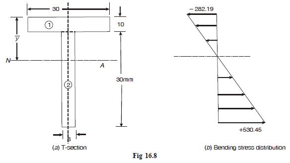
The cross-section of a T-section beam is shown in Fig. 16.8 (a). It is subjected to a bending moment of 1.5 kNm. Plot the distribution of stress due to bending in the beam. N- y 30 10 A 30mm (a) T-section Fig 16.8 -282.19 +530.45 (b) Bending stress distribution
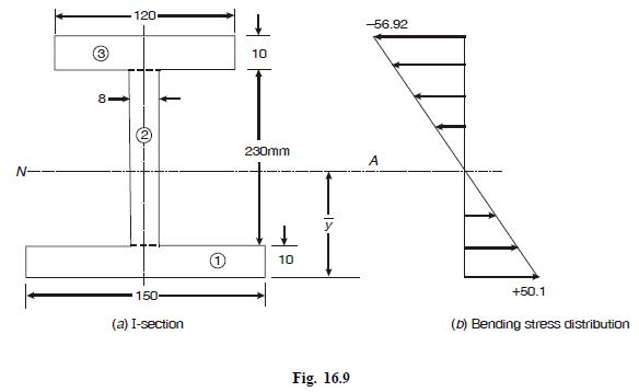
The cross-section of an I-beam is shown in Fig. 16.9. The bending moment at the section is 20 kN.m. Plot the distribution of bending stress in the beam. N- 8- 120 10 10 -56.92 150- (a) I-section 230mm 10 A Fig. 16.9 +50.1 (b) Bending stress distribution
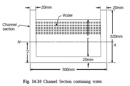
A cast iron channel carries water as shown in Fig. 16.10. It is supported at two points 12 m apart. Density of water is 1000 kg/m3 and that of cast iron 7000 kg/m3. Calculate the depth of water in the channel if the tensile and compressive stresses in bending are not to exceed 20 MPa and 50 MPa
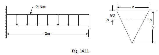
A cantilever beam with triangular cross-section as shown in Fig. 16.11 carries a uniformly distributed load of intensity 2 kN/m over its entire length. If the depth h = 2b, determine the minimum dimensions allowing tensile or compressive stress to be 25 MPa. 2kN/m h/3 NT 2m Fig. 16.11 A
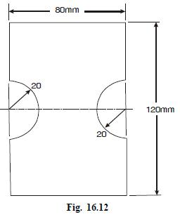
A timber beam as shown in Fig. 16.12 is simply supported on a span of 4 m.The weight of the beam is 10 kN/m3 and the permissible stress in timber is 10 MPa. Calculate the safe point load at mid-span. 80mm 20 20 20 Fig. 16.12 120mm
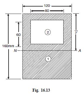
A beam of 3 m length is simply supported at the ends and carries a uniformly distributed load of 40 kN/m over its whole span. The cross-section of the beam is shown in Fig.16.13. Calculate the maximum tensile and compressive stresses in the beam. 120 80 2 y 60 160mm N- 0 A Fig. 16.13
A log of timber 300 mm in diameter is available to be used as a beam.Calculate the following:(a) Dimensions of the strongest rectangular section that can be cut out of it.(b) Maximum span to carry a uniformly distributed load of 3 kN/m to limit the bending stress to 10 MPa.(c) Longest span to use
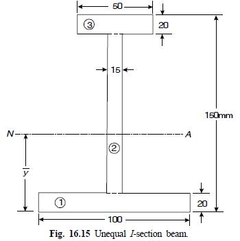
A beam of I-section shown in Fig. 16.15 is subjected to be bending moment of 12 kN.m. Find the maximum tensile and compressive stresses induced in the beam. N-T y 1) 3 -50- 15 (2 20 T -A 150mm 100 Fig. 16.15 Unequal I-section beam. 20
A hollow shaft of diameter ratio 0.6 is required to transmit 500 kW at 100 rpm. The maximum torque being 15% greater than the mean. The shear stress is not to exceed 60 MPa and the angle of twist in a length of 3 m is limited to 1°. Calculate the minimum external diameter satisfying these
Compare the weights of two solid shafts of identical length, one of steel and the other of aluminium alloy, both designed for the same angle of twist per unit length when subjected to the same torque. \(G_{s}=3 G_{a l}\) and \(\gamma_{s}=2 \gamma_{a l}\), where \(\gamma\) specific weight.
A solid aluminium shaft 1m long and 45 mm outside diameter is to be replaced by a tubular steel shaft of the same length and the same outside diameter so that either shaft could carry the same torque and have the same angle of twist over the whole length. What must be the inner radius of the
A solid shaft is to transmit 300 kW at 80 rpm. The shear stress is not to exceed 60 MPa. Find the shaft diameter. Calculate the percentage saving in weight if this shaft were replaced by a hollow one whose internal diameter equals 60 per cent of external diamter.The length, material and maximum
A hollow shaft of diameter ratio 0.6 is required to transmit 450 kW at 100 rpm, the maximum torque being 20 % greater than the mean value. The shear stress is not to exceed 56 MPa and the angle of twist in a length of 3m is not to exceed 1.5 degrees. Calculate the external diameter satisfying above
A solid circular shaft is to transmit 250 kW at 120 rpm. (a) If shear stress is not the exceed 63 MPa, find its diameter. (b) If this shaft is replaced by a hollow shaft whose diameter ratio is 0.6, what percentage saving in weight shall be obtained keeping the material and maximum shear stress
A hollow steel shaft is to be replaced by an aluminium shaft of the same external diameter. The material of steel shaft is 25% stronger than aluminium shaft in shear.Calculate the diameter ratios. Also find the percentage saving in weight assuming that steel is 3 times heavier than aluminum.
A solid shaft of medium carbon steel 100 mm diameter is to be replaced by a hollow shaft of alloy steel. The shear strength of alloy steel is 30% greater than medium carbon steel. The power to be transmitted is increased by 20 % and the speed of rotation decreased by 5%. Determine the maximum
The principal stresses at a point in a piece of material are \(90 \mathrm{MPa}\) tensile and \(60 \mathrm{MPa}\) compressive. Find the intensity and direction of the stress across a plane the normal of which is inclined at \(30^{\circ}\) to the axis of 90 MPa stress.
At a point in a piece of material the intensity of resultant stress on a certain plane is \(50 \mathrm{Mpa}\) inclined at \(30^{\circ}\) to normal to that plane. The plane normal to this has a resultant stress whose normal component is \(30 \mathrm{MPa}\). Find (a) the principal planes and
At a point in a material subjected to two direct stresses on planes at right angles, the resultant stress on a plane \(A\) is \(80 \mathrm{MPa}\) inclined at \(30^{\circ}\) to the normal, and on plane \(B\) is \(40 \mathrm{MPa}\) inclined at \(45^{\circ}\) to the normal. Find the principal stresses
The principal stresses at a point in a material are \(120 \mathrm{MPa}\) and \(60 \mathrm{Mpa}\). Find the magnitude and direction of stress on a plane inclined at \(30^{\circ}\) to the direction of \(60 \mathrm{MPa}\) stress. Find also the plane on which the resultant stress is most oblique and
The state of stress at a point is given by:\[ \sigma_{x}=60 M P a, \sigma_{\mathrm{y}}=-30 M P a, \tau_{\mathrm{xy}}=30 M p a(c c w) \]Calculate (a) principal stresses, (b) principal planes, (c) maximum shear stress, shown the orientation of principal planes and planes of maximum shear stress.
At a point in a load carrying member, the state of stress is as given below.\[ \sigma_{x}=400 \mathrm{MPa}, \sigma_{\mathrm{y}}=-300 \mathrm{MPa}, \tau_{\mathrm{xy}}=200 \mathrm{MPa}(\mathrm{ccw}) \]Draw the Mohr's circle and find the principal stresses and principal planes. Also draw the
. The state of stress at a point is given by\[ \sigma_{x}=-120 \mathrm{MPa}, \sigma_{\mathrm{y}}=180 \mathrm{MPa}, \sigma_{\mathrm{xy}}=80 \mathrm{MPa}(\mathrm{ccw}) \]Draw the Mohr's circle the find the principal stress, principal planes and maximum shear stress. Show the results on stress
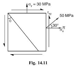
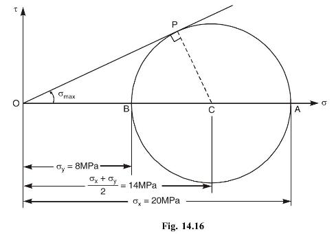
The principal stresses at a point in a stressed body are \(20 \mathrm{MPa}\) and \(8 \mathrm{MPa}\). Determine the maximum obliquity of the resultant stress P Omax A B = 20MPa Fig. 14.16 x + y 2 = 14MPa = 8MPa b
The state of stress at a point is given by:\[ \sigma_{x}=400 \mathrm{MPa}, \sigma_{y}=200 \mathrm{MPa}, \tau_{x y}=100 \mathrm{MPa}(\mathrm{ccw}) \]Calculate the normal, shear and resultant stresses on a plane making an angle of \(30^{\circ}\) with the \(x\)-axis.
The normal stresses on two neutrally perpendicular planes are \(100 \mathrm{MPa}\) (tensile) and \(40 \mathrm{MPa}\) (compressive) together with shear stress of \(70 \mathrm{MPa}\). Determine graphically or otherwise, (a) the magnitude and direction of principal stresses, and (b) the magnitude of
: A bar of \(20 \mathrm{~mm}\) diameter is subjected to a pull of \(20 \mathrm{kN}\). The measured extension over a gauge length of \(200 \mathrm{~mm}\) is \(0.1 \mathrm{~mm}\) and the change in diameter is \(0.0035 \mathrm{~mm}\). Calculate the value of modulus of elasticity, bulk modulus, and
A material is subjected to two mutually perpendicular linear strains together with a shear strain. One of the linear strain is \(250 \times 10^{-6}\) tensile. Determine the magnitude of the other linear strain and shear strain if the principal strains are \(-100 \times 10^{-6}\) and \(+300 \times
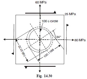
A circle of \(100 \mathrm{~mm}\) diameter is scribed on an aluminium plate before it is loaded as shown in Fig. 14.30. After stressing the circle deforms into an ellipse. Determine the lengths of major and minor axes of the ellipse and there orientation.For aluminium \(\mathrm{E}=10 \mathrm{GPa}\)
Justify the necessity for NC machines.
Define HC, CNC and DNC.
Showing 100 - 200
of 4547
1
2
3
4
5
6
7
8
9
10
11
12
13
14
15
Last
Step by Step Answers