New Semester
Started
Get
50% OFF
Study Help!
--h --m --s
Claim Now
Question Answers
Textbooks
Find textbooks, questions and answers
Oops, something went wrong!
Change your search query and then try again
S
Books
FREE
Study Help
Expert Questions
Accounting
General Management
Mathematics
Finance
Organizational Behaviour
Law
Physics
Operating System
Management Leadership
Sociology
Programming
Marketing
Database
Computer Network
Economics
Textbooks Solutions
Accounting
Managerial Accounting
Management Leadership
Cost Accounting
Statistics
Business Law
Corporate Finance
Finance
Economics
Auditing
Tutors
Online Tutors
Find a Tutor
Hire a Tutor
Become a Tutor
AI Tutor
AI Study Planner
NEW
Sell Books
Search
Search
Sign In
Register
study help
engineering
introduction mechanical engineering
Principles Of Mechanical Engineering 1st Edition Sadhu Singh - Solutions
Explain the working of a NC machine tool with the help of a neat diagram.
What are the main components of a NC machine tool ? Explain their functions.
Which are the two control loop systems for a NC machine ? Explain briefly.
How do you classify NC machine tools ?
Give the applications and advantages of NC machines.
List the advantages of CNC systems over the NC systems.
List the main advantages of DNC.
Compare the NC and CNC machine tools.
Why quick return machanism is used in shaper ?
Define zeroth law of thermodynamics.
What are open, closed and isolated systems ?
Why we use Psychometric charts ?
What is air conditioning ?
Define specific speed of turbine.
Explain rope and chain drives.
What is Poisson’s ratio ?
What is MCU in NC machines ?
Explain drilling m/c with diagram.
Define laws of thermodynamics.
Explain throttling calorimeter.
Explain simple refrigeration vapour compression cycle.
What is coefficient of performance (COP) ?
Explain Pelton turbine with diagram.
Explain rotary water pumps.
Explain single plate clutch.
Explain belt drive for power transmission.
What is Hooke’s Law ? Derive an expression for relationship between elastic constants.
Explain stress & strain.
Explain NC machines in detail.
Write down difference between NC & CNC machines.
Explain manufacturing systems.
Explain working principle of drilling machine.
Define internal energy and enthalpy.
Define refrigeration and air conditioning.
Why Francis turbine is called mixed flow turbine.Explain belt drive.
What is Poission’s ratio ?
Explain four advantages of NC machine.
What is Zeroth law of thermodynamics.
Why we use Psycheometric charts ?
What is the difference between spur and helical gear ?
Explain different types of chips in metal cutting?
Define I, II and III law of Thermodynamics.
What is throttling calorimeter ?
Explain 5 operations of lathe machine.
Define human comfort.
Derive an expression for specific speed of turbine.
Explain reciprocating water pumps.
Explain with neat diagram, multiplate clutch.
Define different types of gear.
Explain elastic constants and their relationship.
Explain NC machine in detail.
Define manufacturing system and compare NC and CNC machines.
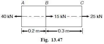
A steel bar of diameter \(15 \mathrm{~mm}\) is loaded as shown in Fig. 13.47. Calculate the stresses in each part and total change in length. Take \(E=200 \mathrm{GPa}\). 40 kN A B C 15 kN - 25 kN 0.2 m 0.3m- Fig. 13.47
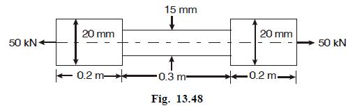
Find the change in length of the bar loaded as shown in Fig. 13.48. Take \(E=200 \mathrm{GPa}\). 50 kN 20 mm 15 mm 0.2 m 0.3 m Fig. 13.48 20 mm 50 kN 0.2 m
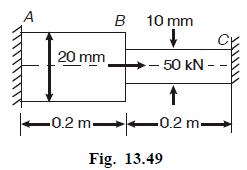
Calculate the change in length of the bar shown in Fig. 13.49. Take \(E=200 \mathrm{GPa}\). A B 10 mm 20 mm - 50 kN - 0.2m 0.2 m- Fig. 13.49
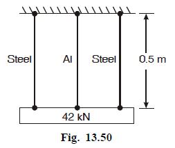
A block weighing \(42 \mathrm{kN}\) is supported by three wires as shown in Fig. 13.50. The two outer steel wires have an area of \(100 \mathrm{~mm}^{2}\) each, whereas the middle aluminium wire has an area of 200 \(\mathrm{mm}^{2}\). Calculate the stresses in the wires. Take \(E_{s}=200
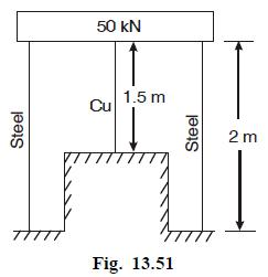
Two steel wires and a copper wire support a load of \(50 \mathrm{kN}\) as shown in Fig. 13.51. The diameter of steel wire is \(20 \mathrm{~mm}\) and that of copper wire \(15 \mathrm{~mm}\). If \(E_{s}=200 \mathrm{GPa}\) and \(E_{c}=100 \mathrm{GPa}\), calculate the stresses induced in the wire.
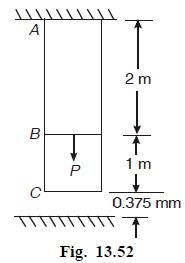
A steel rod clamped as its upper end, has a cross-sectional area of \(20 \mathrm{~cm}^{2}\). Between its lower end and a rigid plane, there was a clearance of \(0.375 \mathrm{~mm}\) before the load was applied. Determine the stresses in the upper and lower parts of the rod due to the force \(P=225
A gun metal rod 2 on diameter screwed at the ends, passes through a steel tube \(2.5 \mathrm{~cm}\) internal and \(3 \mathrm{~cm}\) external diameter. dimameter. The temperature of the whole assembly is raised to \(130^{\circ} \mathrm{C}\) and nuts on the rod are screwed lightly home on the ends of
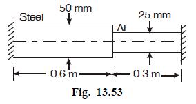
A composite bar made up of aluminium and steel is held between two supports as shown in Fig. 13.53.The bars are stress free at a temperature of \(38^{\circ} \mathrm{C}\). What will be the stresses in the two bars when the temperature is \(21^{\circ} \mathrm{C}\), if \((a)\) the supports are rigid,
An unknown weight falls throught \(10 \mathrm{~mm}\) on a collar rigidly attached to the lower end of a vertical bar, \(3 \mathrm{~m}\) long and \(6 \mathrm{~cm}^{2}\) in section. If the maximum instantaneous extension is known to be \(2 \mathrm{~mm}\), what is the corresponding stress and the
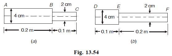
Two similar round bars " \(a\) " and " \(b\) " are each \(0.3 \mathrm{~m}\) long a shown in Fig 13.54. The bar " \(a\) " receives an axial blow which produces a maximum stress of \(200 \mathrm{MPa}\). Find the maximum stress produced in bar " \(b\) " by the same blow. A 4 cm 0.2 m (a) B 2 cm D C
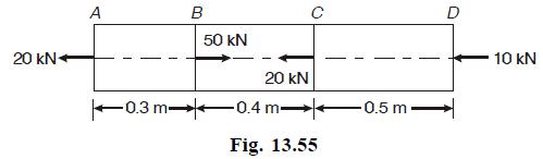
Calculate the total elongation of the bar loaded or shown in Fig.13.55. E = 200 GPa, area of cross-section of bar is \(500 \mathrm{~mm}^{2}\) 20 kN A B C D 50 kN 20 kN 0.3 m 0.4 m -0.5 m. Fig. 13.55 10 kN
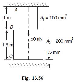
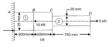
Calculate the stresses in the bars loaded as shown in Fig.13.56. \(E=200 \mathrm{GPa}\) A 1 m B 2 A = 100 mm | 50 kN 1.5 m Fig. 13.56 A = 200 mm 1.5 mm
A steel specimen \(2 \mathrm{~cm}^{2}\) are of cross-section elongates by \(0.1 \mathrm{~mm}\) over a gauge length of \(50 \mathrm{~mm}\) under an axial load of \(40 \mathrm{kN}\). Calculate the strain energy in the specimen. If its limit of proportionality is \(45 \mathrm{MPa}\), find the
A bar \(0.5 \mathrm{~m}\) long has \(2 \mathrm{~cm}^{2}\) area of cross-section for \(0.4 \mathrm{~m}\) of its length and \(1 \mathrm{~cm}^{2}\) for the remaining length. A load of \(40 \mathrm{kN}\) falls on the collar provided at the lower end of the bar, the other end being fixed, from a height
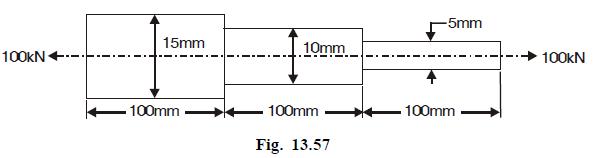
Calculate the total elongation of the steel bar shown in Fig. 13.57. \(E=200 \mathrm{GPa}\). 100kN 15mm 10mm .100mm 100mm Fig. 13.57 -5mm .100mm 100kN
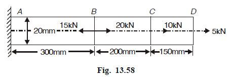
Calculate the stresses in each portion of the bar shown in Fig. 13.58. A 15kN 20mm- 300mm B C D 20kN 10kN 5kN 200mm 150mm Fig. 13.58
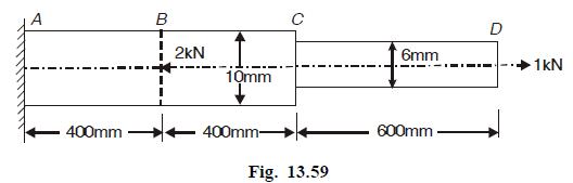
A stepped bar is loaded as shown in Fig.13.59. Calculate the stresses in each portion and total elongation. \(E=100 \mathrm{GPa}\). A B 2KN 10mm C 6mm 400mm 400mm- 600mm Fig. 13.59 D 1KN
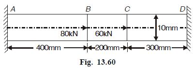
Determine the stresses in all parts of the bar shown in Fig. 13.60 and rigidly clamped at the ends. A B 10mm 80kN 60kN 400mm -200mm -300mm- Fig. 13.60
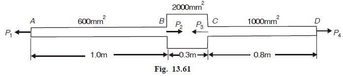
A member \(A B C D\) is subjected to point loads \(P_{1}\) to \(P_{4}\) as shown in Fig. 13.61. Find the value of force \(P_{2}\) for equilibrium, if \(P_{1}=40 \mathrm{kN}, P_{2}=400 \mathrm{kN}\) and \(P_{4}=120 \mathrm{kN}\). Also calculate the total elongation, if \(E=200 \mathrm{GPa}\). 2000mm
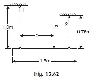
A rigid beam \(A B\) is suspended horizontally from rods land 2 as shown in Fig. 13.62. Rod 1 is of steel and has \(15 \mathrm{~mm}\) diameter, while rod 2 is of copper and has \(20 \mathrm{~mm}\) diameter. At what distance from rod 1 must the load \(P\) be applied if the beam \(A B\) is to remain
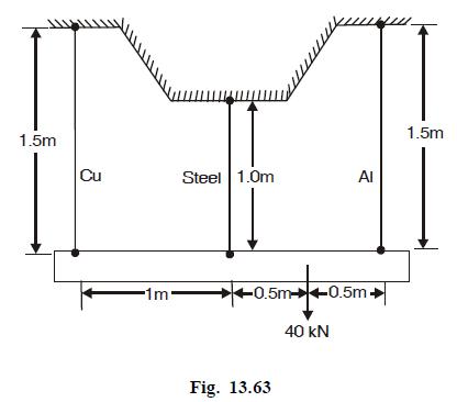
A rigid bar is suspended from three rods and loaded as shown in Fig.13.63. The crossssectional area of copper,steel and aluminium rods are \(100 \mathrm{~mm}^{2}\) and \(150 \mathrm{~mm}^{2}\) respectively Calculate the stresses in the rods. Take \(E_{s}=200 \mathrm{GPa}, E_{c}=100 \mathrm{GPa}\),
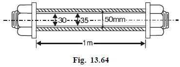
A steel bolt is put through a copper tube as shown in Fig. 13.64. The pitch of screw threads of bolt is \(5 \mathrm{~mm}\). Calculate the stresses in the bolt and tube when the nut is turned through one-quarter of a revolution, \(E_{s}=2 E_{c}=200 \mathrm{GPa}\). 30-35-50mm-. -1m- Fig. 13.64
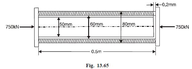
A solid steel bar \(0.5 \mathrm{~m}\) long and \(50 \mathrm{~mm}\) diameter is placed inside and aluminium tube having inside and outside diameters \(60 \mathrm{~mm}\) and \(80 \mathrm{~mm}\) respectively. The aluminium tube is \(0.2 \mathrm{~mm}\) longer than steel bar. An axial load of \(750
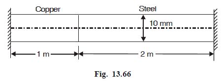
A rod of constant cross-section is tightly clamped between two rigid supports as shown in Fig. 13.66. After clamping the temperature of rod is incressed by \(60^{\circ} \mathrm{C}\). Calculate the stresses in two parts of the rod. \(E_{s}=200 \mathrm{GPa} . E_{c}=100 \mathrm{GPa}, \alpha_{s}=12
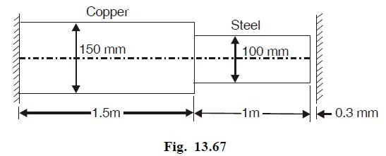
Calculate the stresses in the bar shown in Fig. 13.67. if its temperature is raised by \(40^{\circ}\) C. \(E_{s}=2 E_{c}=200 \mathrm{GPa}, \alpha_{s}=12.5 \times 10^{-6} \mathrm{per}^{\circ} \mathrm{C}\), and \(\alpha_{c}=17.5 \times 10^{-6}\) per \({ }^{\circ} \mathrm{C}\). Copper 150 mm Steel 100
Two rods are joined together one behind the other and the extreme ends are built in the fixed supports. One rod is of steel \(3 \mathrm{~m}\) long and \(600 \mathrm{~mm}^{2}\) cross-sectional area. The other rod is of bronze \(0.8 \mathrm{~m}\) long and \(1200 \mathrm{~mm}^{2}\) cross-sectional
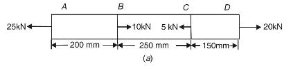
A steel bar 20 mm diameter is loaded as shown in Fig. 13.11 (a). Determine the stresses in each part. 25kN A B C D 10kN 5 kN 20kN 200 mm 250 mm 150mm- (a)
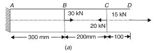
A steel bar of 25 mm diameter is loaded as shown in Fig. 13.12 (a). Calculate the stress in each portion and the total elongation. Take \(E=200 \mathrm{GPa}\). B 30 kN 20 kN C D 15 kN -200mm 100 -300 mm (a)
A stepped bar is loaded as shown in Fig. 13.13 (a). Calculate the stress in each part and total elongation. \(E=200 \mathrm{GPa}\). A B 25 mm+ 25 10 kN 4500mm 500mm (a) 20 mm 2 _ 750 mm D 5 kN
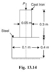
A pillar is shown in Fig. 13.14. The total contraction of the pillar is \(0.25 \mathrm{~mm}\). If \(E_{s}=200 \mathrm{GPa}\) and \(E_{C I}=\) \(120 \mathrm{GPa}\), find the value of load \(P\). Cast Iron Steel 0.05 m 0.3 m 0.1 m 0.4 m m- Fig. 13.14
A steel rod \(60 \mathrm{~mm}\) in diameter and \(2 \mathrm{~m}\) long is subjected to a pull of \(120 \mathrm{kN}\). It the strain is to increase by 10 percent, find the length of \(20 \mathrm{~mm}\) diameter bore under the same pull. Take \(E=210 \mathrm{GPa}\)
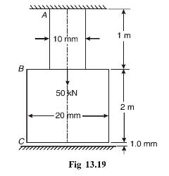
A stepped bar as shown in Fig. 13.19 is held between two rigid supports such that there is a gap of \(1.0 \mathrm{~mm}\) between the lower support and the bar. Calculate the stresses in the bar. Take \(E=200\) GPa. B A 10 mm 1 m 50 kN 2 m 20 mm- 1.0 mm Fig 13.19
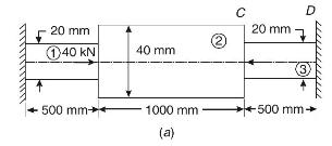
Calculate the stresses in \(A B\) and \(B C\) of the bar \(A B C\) as loaded in Fig. 13.20(a). 20 mm 140 kN 40 mm C D 20 mm 3. 500 mm 1000 mm 500 mm- (a)
The following data refer to a circular bar subjected to a tensile test:Diameter of bar \(=25 \mathrm{~mm}\)Tensile load \(=45 \mathrm{kN}\)Gauge length \(=300 \mathrm{~mm}\)Extension \(=0.133 \mathrm{~mm}\)Decrease in diameter \(=0.0033 \mathrm{~mm}\)Determine (a) Posisson's ratio, and (b)Young's
A machine component made of steel having tensile yield strength \(380 \mathrm{MPa}\) is subjected to axial load of \(5 \mathrm{kN}\). The area of cross- section of the component is \(25 \mathrm{~mm}^{2}\).Determine the factor of safety.
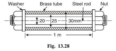
A steel rod \(20 \mathrm{~mm}\) diameter is passed through a brass tube \(25 \mathrm{~mm}\) internal diameter and \(30 \mathrm{~mm}\) external diameter. The tube is \(1 \mathrm{~m}\) long and is closed by thin rigid washers and fastened by nuts, screwed to the rod, as shown in Fig. 13.28. the nuts
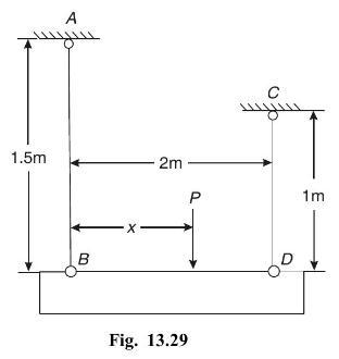
A rigid beam \(B D\) is suspended from two rods \(A B\) and \(C D\) as shown in Fig. 13.29. Rod \(A B\) is of steel of \(20 \mathrm{~mm}\) diameter and rod \(B\) is of copper of \(25 \mathrm{~mm}\) diameter. At what distance from rod \(A B\) the load \(P\) be applied if the beam is to remain
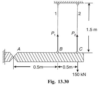
Determine the stresses in the rods loaded as shown in Fig . 13.30 and having the same area of cross-section of \(5 \mathrm{~cm}^{2}\). A 0.5m 1 2 P P2 B -0.5m Fig. 13.30 150 kN 1.5 m
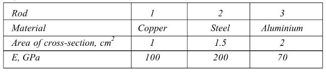
A rigid bar is suspended from three rods and loaded as shown in Fig.13.31. Determine the stresses in the rods.The given data is: Rod Material 1 2 3 Copper Steel Aluminium cm 1 1.5 2 100 200 70 Area of cross-section, cm E, GPa
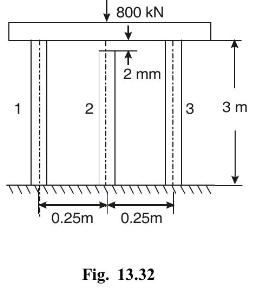
A rigid beam is placed on there columns of identical cross- sectional areas of \(200 \mathrm{~cm}^{2}\) each as shown in Fig. 13.32. Calculate the stresses in the columns if there was a gap of \(2 \mathrm{~mm}\) between the beam and the middle column before the load wass applied. Take \(E=18 . G P
A solid steel bar \(0.5 \mathrm{~m}\) long and \(50 \mathrm{~mm}\) diameter is placed inside and aluminium tube having \(60 \mathrm{~mm}\) inside and \(80 \mathrm{~mm}\) outside diameter. the aluminium tube is \(0.2 \mathrm{~mm}\) longer than the steel bar. An axial load of \(500 \mathrm{kN}\) is
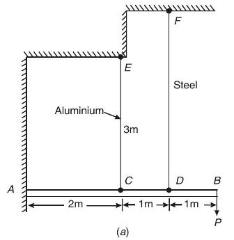
A horizontal beam \(A B\) is supported on two cables \(C E\) and \(D F\) as shown in Fig 13.34(a) Calculate the values of \(P\) when the strain in \(D F\) is \(3 \times 10^{-4}\) Assume that beam \(A B\) does not bend. \(A_{a}=A_{s}=600 \mathrm{~mm}^{2}, E_{a}=70 \mathrm{GPa}, E_{s}=210
A compound bar loaded as shown in Fig. 13.35 has a gap of \(1.0 \mathrm{~mm}\). Calculate The stresses in the two bars. \(E_{s}=200 \mathrm{GP}_{a}, E_{c i}=105 \mathrm{GPa}\).
A rectangular steel bar \(25 \mathrm{~mm} \times 12 \mathrm{~mm}\) and \(0.5 \mathrm{~m}\) long is subjected to an axial tensile load of \(10 \mathrm{kN}\). Calculate the change in dimensions if \(E=200 \mathrm{GPa}\) and poisson's ratio \(=0.30\)
In a tensile test on mild test on mild steel, the gauge length was \(50 \mathrm{~mm}\) and diameter \(10 \mathrm{~mm}\). The load at the proportional limit was \(30 \mathrm{kN}\) and at the upper yield point 32 \(k N\). The extension on \(50 \mathrm{~mm}\) gauge length was \(0.028 \mathrm{~mm}\)
A steel column \(4 \mathrm{~m}\) hight \(250 \mathrm{~mm}\) exetrnal diameter and \(200 \mathrm{~mm}\) inside diameter is subjected to an axial compressive load of \(40 \mathrm{kN}\) at the top. The density of steel is \(7470 \mathrm{~kg} . \mathrm{m}^{3}\).Calculate the stress at the top and
\(A\) short reinforced concrete column has \(600 \mathrm{~cm}^{2}\) area of cross-section. The column is reinforced with 4 steel rods arranged symmetrically, eafch having \(10 \mathrm{~cm}^{2}\) crosssectional area. The column is subjected to an axial load of \(800 \mathrm{kN} . E_{s}=200
A load of \(2 \mathrm{kN}\) is suspended from two rods as shown is Fig. 13.36. Rod AB is of steel of \(15 \mathrm{~mm}\) diameter and rod CD of copper having \(10 \mathrm{~mm}\) diameter.Calculate the distance \(x\) so that the the bar BD remains horizontal. Also calculate the stresses production
Showing 200 - 300
of 4547
1
2
3
4
5
6
7
8
9
10
11
12
13
14
15
Last
Step by Step Answers