New Semester
Started
Get
50% OFF
Study Help!
--h --m --s
Claim Now
Question Answers
Textbooks
Find textbooks, questions and answers
Oops, something went wrong!
Change your search query and then try again
S
Books
FREE
Study Help
Expert Questions
Accounting
General Management
Mathematics
Finance
Organizational Behaviour
Law
Physics
Operating System
Management Leadership
Sociology
Programming
Marketing
Database
Computer Network
Economics
Textbooks Solutions
Accounting
Managerial Accounting
Management Leadership
Cost Accounting
Statistics
Business Law
Corporate Finance
Finance
Economics
Auditing
Tutors
Online Tutors
Find a Tutor
Hire a Tutor
Become a Tutor
AI Tutor
AI Study Planner
NEW
Sell Books
Search
Search
Sign In
Register
study help
computer science
modern database management 13th edition
Modern Control Systems 13th Global Edition Robert Bishop Richard Dorf - Solutions
DP10.4 A high-speed train is under development in Texas[21] with a design based on the French Train à Grande Vitesse (TGV). Train speeds of 186 miles per hour are foreseen. To achieve these speeds on tight curves, the train may use independent axles combined with the ability to tilt the train.
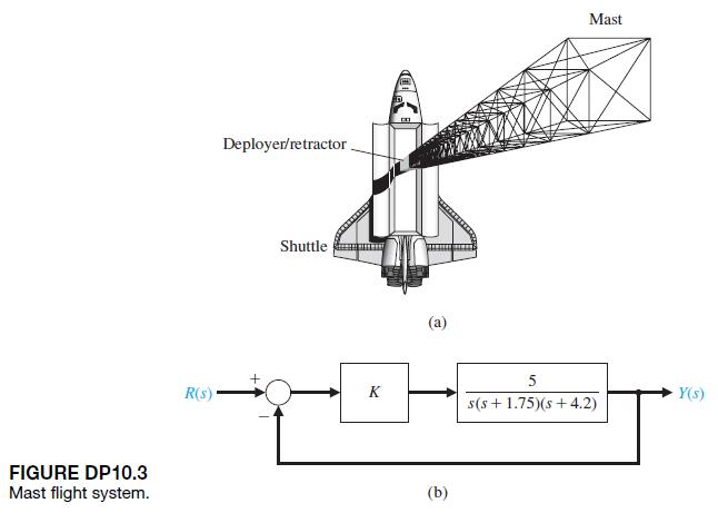
DP10.3 NASA has identified the need for large deployable space structures, which will be constructed of lightweight materials and will contain large numbers of joints or structural connections. This need is evident for programs such as the space station. These deployable space structures may have
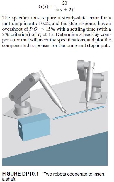
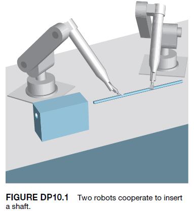
DP10.1 In Figure DP10.1, two robots are shown cooperating with each other to manipulate a long shaft to insert it into the hole in the block resting on the table.Long part insertion is a good example of a task that can benefit from cooperative control. The unity feedback control system of one robot
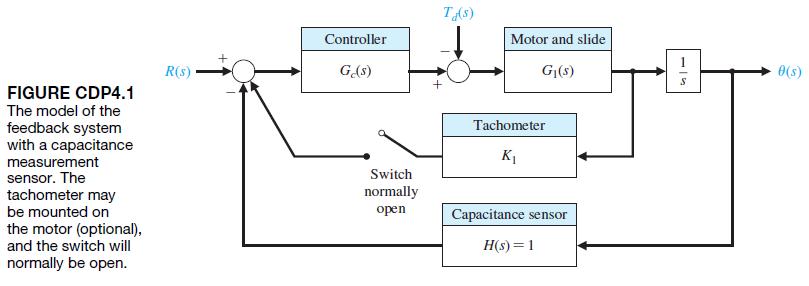
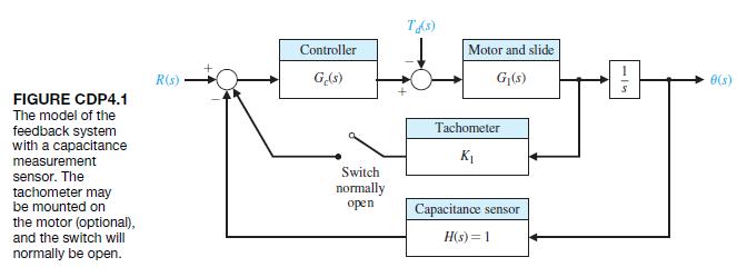
The capstan-slide system of Figure CDP4.1 uses a PD controller. Determine the necessary values of the gain constants of the PD controller so that the deadbeat response is achieved. Also, we want the settling time (with a 2% criterion) to be Ts … 250 ms.Verify the results. Controller R(s) Ge(s)
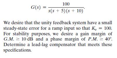
AP10.9 The plant dynamics of a chemical process are represented by G(s) = 100 s(s + 5)(s + 10) We desire that the unity feedback system have a small steady-state error for a ramp input so that K, = 100. For stability purposes, we desire a gain margin of G.M. 10 dB and a phase margin of P.M. 40.
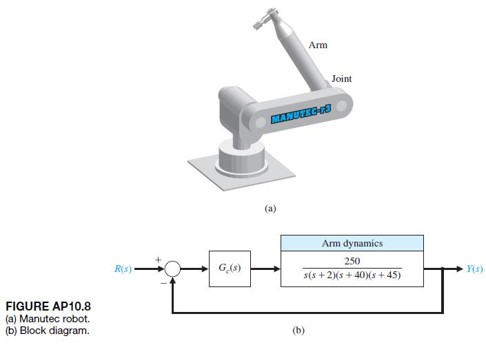
AP10.8 The Manutec robot has large inertia and arm length resulting in a challenging control problem, as shown in Figure AP10.8(a). The block diagram model of the system is shown in Figure AP10.8(b).The percentage overshoot for a step input should be P.O. … 20, with a rise time of Tr … 12 s and
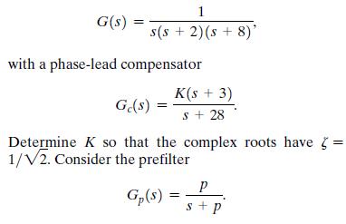
A unity feedback system has(a) Determine the percent overshoot and rise time for Gp1s2 = 1 and for p = 3. (b) Select an appropriate value for p that will give an overshoot of P.O. … 1, and compare the results. G(s) = 1 s(s + 2)(s + 8)' with a phase-lead compensator K(s + 3) Ge(s) s + 28 Determine
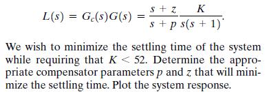
AP10.6 Consider a unity feedback system with loop transfer function S+ Z K L(s) = Ge(s)G(s) = s+ps(s+1)* We wish to minimize the settling time of the system while requiring that K < 52. Determine the appro- priate compensator parameters p and z that will mini- mize the settling time. Plot the
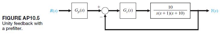
AP10.5 A unity feedback system is shown in Figure AP10.5. We want the step response of the system to have a percent overshoot of P.O. … 10, and a settling time (with a 2% criterion) of Ts … 4 s.(a) Design a phase-lead compensator Gc1s2 to achieve the dominant roots desired. (b) Determine the
AP10.4 A DC motor control system with unity feedback has the form shown in Figure AP10.4. Select K1 and K2 so that the system response has a settling time (with a 2% criterion) Ts … 1 s and a percent overshoot of P.O. … 5, for a step input. FIGURE AP10.4 Motor control system. R(s) K Velocity
AP10.3 The system of Advanced Problem AP10.1 is required to have a percent overshoot of P.O. … 13, with a steady-state error for a unit ramp input less than 0.125 1Kv = 82. Design a proportional plus integral(PI) controller to meet the specifications.
The system of Advanced Problem AP10.1 is to have a percent overshoot of P.O. … 13,. In addition, we desire that the steady-state error for a unit ramp input will be less than 0.125 1Kv = 82 [24]. Design a lag compensator to meet the specifications. Check the resulting percent overshoot and
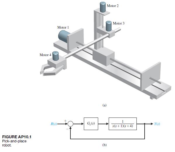
A three-axis pick-and-place application requires the precise movement of a robotic arm in threedimensional space, as shown in Figure AP10.1 for joint 2. The arm has specific linear paths it must follow to avoid other pieces of machinery. The overshoot for a step input should be less than 13%.(a)
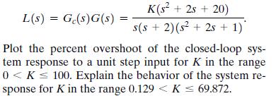
P10.43 A unity feedback system has a loop transfer function L(s) = Ge(s)G(s): K(s + 2s+20) s(s2)(s2 2s + 1)* Plot the percent overshoot of the closed-loop sys- tem response to a unit step input for K in the range 0 < K < 100. Explain the behavior of the system re- sponse for K in the range 0.129 <
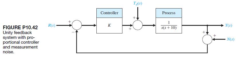
P10.42 Consider the system shown in Figure P10.42 and let R1s2 = 0 and Td1s2 = 0. Design the compensator Gc1s2 = K such that, in the steady-state, the response of the system y1t2 is less than -40 dB when the noise N1s2 is a sinusoidal input at a frequency of v Ú 100 rad>s. FIGURE P10.42 Unity
For the system and requirements of Problem P10.39, determine the required compensator when the steady-state error for the ramp input must be equal to 0.02.
A unity feedback system has a plant 40 G(s) s(s + 2)* We desire that the phase margin be P.M. = 30. For a ramp input r(t) =t, we want the steady-state error to be equal to 0.05. Design a phase-lag compensator to satisfy the requirements. Verify the results.
P10.38 A unity feedback system has a plant 40 G(s) s(s + 2)* We desire to have a phase margin of P.M. = 30 and a relatively large bandwidth. Select the crossover fre- quency w 10 rad/s, and design a phase-lead com- pensator. Verify the results.
P10.37 A unity feedback system has the loop transfer functionDesign a compensator Gc1s2 so that the percent overshoot for a step input R1s2 is P.O. … 5, and the steady-state error is less than 1%. Determine the bandwidth of the system. G(s)- 1 (s+2)(s+8) ($)9 = ($)9($)9 = (s)7
A system transfer function is a pure time delay of 0.5 s, so that G1s2 = e-s>2. Select a compensator Gc1s2 so that the steady-state error for a step input is less than 2% of the magnitude of the step and the phase margin is P.M. Ú 30°. Determine the bandwidth of the compensated system and plot
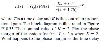
P10.35 A unity feedback system has the loop transfer functionincreases? What is the maximum time delay allowed before the system becomes unstable? Ks + 0.54 L(s) = Ge(s)G(s) -T's = s(s + 1.76) where T is a time delay and K is the controller propor- tional gain. The block diagram is illustrated in
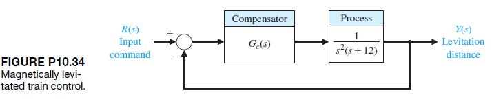
P10.34 A magnetically levitated train operated in Berlin, Germany from 1989–1991. Fully automated trains can run at short intervals and operate with excellent energy efficiency. The control system for the levitation of the car is shown in Figure P10.34. Select a compensator so that the phase
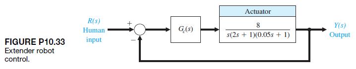
Consider the block diagram of the extender robot system shown in Figure P10.33 [14]. The goal is that the compensated system will have a velocity constant Kv equal to 80, so that the settling time (with a 2%criterion) will be Ts = 1.6 s, and that the percent overshoot will be P.O. = 16,, so that
When a motor drives a flexible structure, the structure’s natural frequencies, as compared to the bandwidth of the servodrive, determine the contribution of the structural flexibility to the errors of the resulting motion. In current industrial robots, the drives are often relatively slow, and
An automated guided vehicle (AGV) can be considered as an automated mobile conveyor designed to transport materials. Most AGVs require some type of guide path. The steering stability of the guidance control system has not been fully solved. The slight“snaking” of the AGV about the track
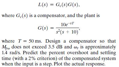
A liquid-level control system has a loop transfer function L(s) = Ge(s)G(s), where Ge(s) is a compensator, and the plant is G(s) 10e-ST s(s+10) where T50 ms. Design a compensator so that Mpa does not exceed 3.5 dB and w, is approximately 1.4 rad/s. Predict the percent overshoot and settling time
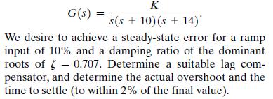
P10.28 An adaptive suspension vehicle uses a legged locomotion principle. The control of the leg can be represented by a unity feedback system with [12] G(s) K s(s +10) (s +14) We desire to achieve a steady-state error for a ramp input of 10% and a damping ratio of the dominant roots of = 0.707.
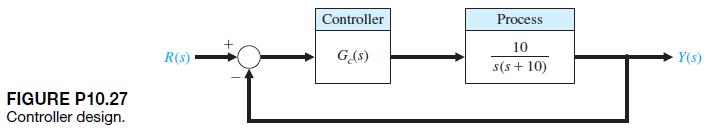
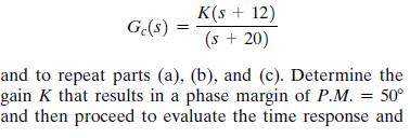
An engineering design team is attempting to control a process shown in Figure P10.27. It is agreed that a system with a phase margin of P.M. = 50° is acceptable.Determine Gc1s2.First, let Gc1s2 = K and find (a) a value of K that yields a phase margin of P.M. = 50° and the system step response for
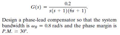
P10.26 A computer uses a printer as a fast output device.We desire to maintain accurate position control while moving the paper rapidly through the printer.Consider a system with unity feedback and a transfer function for the motor and amplifier of G(s) = 0.2 s(s + 1)(6s+ 1) Design a phase-lead
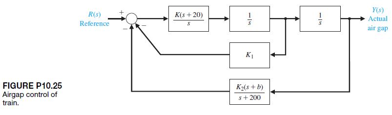
P10.25 The possibility of overcoming wheel friction, wear, and vibration by contactless suspension for passenger-carrying mass-transit vehicles is being investigated throughout the world. One design uses a magnetic suspension with an attraction force between the vehicle and the guideway with an
The stability and performance of the rotation of a robot (similar to waist rotation) presents a challenging control problem. The system requires high gains in order to achieve high resolution; yet a large percent overshoot of the transient response cannot be tolerated.The block diagram of an
P10.23 A system the loop transfer function with unity feedback hasWe desire the steady-state error to a step input to be approximately 5% and the phase margin to be P.M. = 45°. Design a phase-lag compensator to meet these specifications. L(s)G(s)G(s) = Ge(s) K (s + 6)2
P10.22 For the system of Problem P10.20, we wish to achieve the same phase margin and Kv, but in addition, we wish to limit the bandwidth to 2 rad/s … vB … 10 rad/s. Use a lead-lag compensation to compensate the system. The compensator could be of the formwhere a is to be selected for the
For the system of Problem P10.20, design a phaselag compensator to yield the desired specifications, with the exception that a bandwidth vB Ú 2 rad/s will be acceptable.
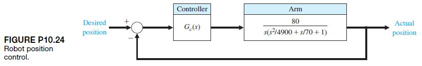
An uncompensated control system with unity feedback has a plant transfer function G(s) K s(s/2+1)(s/6+1)* We want to have a velocity error constant of K, = 20. We also want to have a phase margin of P.M. 45 and a closed-loop bandwidth wg 4 rad/s. Use two identical cascaded phase-lead compensators
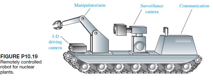
There have been significant developments in the application of robotics technology to nuclear power plant maintenance problems. Thus far, robotics technology in the nuclear industry has been used primarily on spent-fuel reprocessing and waste management.The industry is applying the technology to
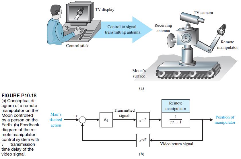
NASA is developing remote manipulators that can be used to extend the hand and the power of humankind through space by means of radio. A concept of a remote manipulator is shown in Figure P10.18(a)[11, 22]. The closed-loop control is shown schematically in Figure P10.18(b). Assuming an average
P10.17 A unity feedback control system for a robot submarine has a plant with a third-order transfer function[20]:We want the percent overshoot to be P.O. = 7.5, for a step input and the settling time (with a 2% criterion)of the system be Ts = 400 ms. Find a suitable lead compensator by using root
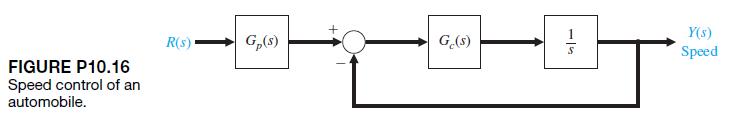
P10.16 A driver and car may be represented by the simplified model shown in Figure P10.16 [17]. The goal is to have the speed adjust to a step input with a percent overshoot of P.O. … 10, and a settling time (with a 2% criterion) of Ts = 1 s. Select a proportional plus integral (PI) controller to
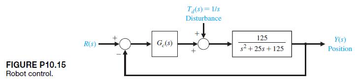
P10.15 A robot with an extended arm has a heavy load, whose effect is a disturbance, as shown in Figure P10.15 [22]. Let R1s2 = 0 and design Gc1s2 so that the effect of the disturbance is less than 20% of the openloop system effect. FIGURE P10.15 Robot control. R(s) Ge(s) Ta(s)=1/s Disturbance 125
For the system described in Problem P10.13, the goal is to achieve a phase margin of P.M. = 50° with the additional requirement that the time to settle (to within 2% of the final value) is Ts … 4 s. Design a phase-lead compensator to meet the specifications. As before, we require Kv = 2. FIGURE
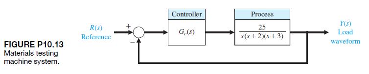
Materials testing requires the design of control systems that can faithfully reproduce normal specimen operating environments over a range of specimen parameters [23]. From the control system design viewpoint, a materials-testing machine system can be considered a servomechanism in which we want to
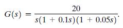
A unity feedback system has a plant 20 G(s) s(10.1s) (1 + 0.05s)
A unity feedback control system has the loop transfer function L(s) = Ge(s)G(s) = Ge(s)- 160 Select a lead-lag compensator so that the percent overshoot for a step input is P.O. < 5% and the set- tling time (with a 2% criterion) is T, 1 s. It also is desired that the acceleration constant Ka be
A unity feedback system has the loop transfer function L(s)G(s)G(s) = Ge(s) 5 s(s + 5s + 12) (a) Determine the step response when Ge(s) = 1, and calculate the settling time and steady state for a ramp input r(t) t,t 0. (b) Design a phase-lag compen- sator using the root locus method so that the
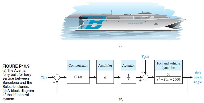
The Avemar ferry, shown in Figure P10.9(a), is a large 670-ton ferry hydrofoil built for Mediterranean ferry service. It is capable of 45 knots (52 mph) [29].The boat’s appearance, like its performance, derives from the innovative design of the narrow “wavepiercing”hulls which move through
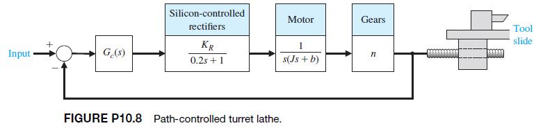
P10.8 A numerical path-controlled machine turret lathe is an interesting problem in attaining sufficient accuracy[2, 23]. A block diagram of a turret lathe control system is shown in Figure P10.8. The gear ratio is n = 0.2, J = 10-3, and b = 2.0 * 10-2. It is necessary to attain an accuracy of 5 *
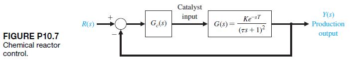
P10.7 A chemical reactor process whose production rate is a function of catalyst addition is shown in block diagram form in Figure P10.7 [10]. The time delay is T = 50 s, and the time constant t is approximately 40 s. The gain of the process is K = 1. Design a compensator using Bode plot methods in
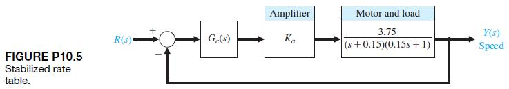
P10.6 Repeat Problem P10.5 by using a phase-lead compensator and compare the results.Data From in P10.5 A stabilized precision rate table uses a precision tachometer and a DC direct-drive torque motor, as shown in Figure P10.5. We want to maintain a high steady-state accuracy for the speed control.
P10.5 A stabilized precision rate table uses a precision tachometer and a DC direct-drive torque motor, as shown in Figure P10.5. We want to maintain a high steady-state accuracy for the speed control. To obtain a zero steady-state error for a step command design, select a proportional plus
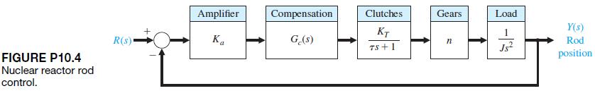
P10.4 Magnetic particle clutches are useful actuator devices for high power requirements because they can typically provide a 200-W mechanical power output.The particle clutches provide a high torque-to- inertia ratio and fast time-constant response. A particle clutch positioning system for nuclear
P10.3 A simplified version of the attitude rate control for a supersonic aircraft is shown in Figure P10.3. When the vehicle is flying at four times the speed of sound(Mach 4) at an altitude of 100,000 ft, the parameters are [26]Design a compensator Gc1s2 so that the response to a step input has a
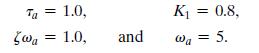
A magnetic tape recorder transport for modern computers requires a high-accuracy, rapid- response control system. The requirements for a specific transport are as follows: (1) The tape must stop or start in 10 ms, and (2) it must be possible to read 45,000 characters per second. This system is
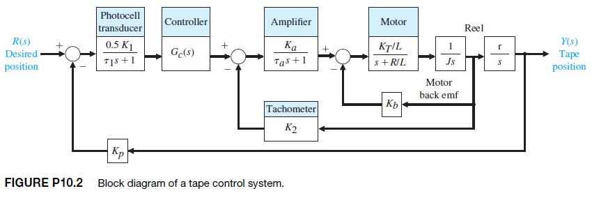
The design of a lunar excursion module is an interesting control problem. The attitude control system for the lunar vehicle is shown in Figure P10.1. The vehicle damping is negligible, and the attitude is controlled by gas jets. The torque, as a first approximation, will be considered to be
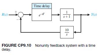
CP9.10 A closed-loop feedback system is shown in Figure CP9.10. (a) Obtain the Nyquist plot and determine the phase margin. Assume that the time delay T = 0 s.(b) Compute the phase margin when T = 0.05 s.(c) Determine the minimum time delay that destabilizes the closed-loop system. R(s) Time delay
For the system in CP9.8, use the nichols function to obtain the Nichols chart and determine the phase margin and gain margin.Data From in CP9.8 Consider the system represented in state variable x(t *() = [230]
CP9.8 Consider the system represented in state variable x(t *() = [230]
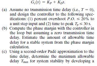
An engineering laboratory has presented a plan to operate an Earth-orbiting satellite that is to be controlled from a ground station. A block diagram of the proposed system is shown in Figure CP9.7.It takes T seconds for a signal to reach the spacecraft from the ground station and the identical
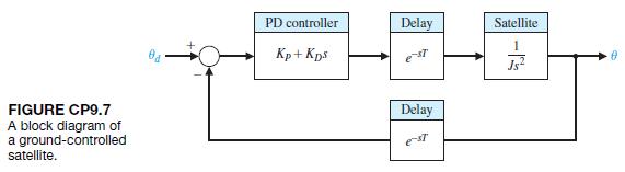
CP9.6 A block diagram of the yaw acceleration control system for a bank-to-turn missile is shown in Figure CP9.6. The input is yaw acceleration command (in g’s), and the output is missile yaw acceleration (in g’s). The controller is specified to be a proportional, integral(PI) controller. The
Consider the paper machine control in Figure AP9.4. Develop an m-file to plot the bandwidth of the closed-loop system as K varies in the interval 1 … K … 50.
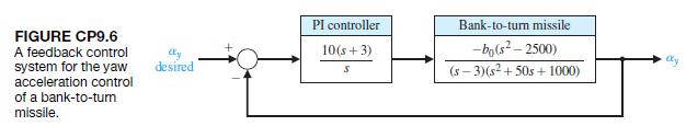
A negative feedback control system has the loop transfer function = L(s) G(s)G(s) - = Ke-Ta S+15 (a) When T=0.05 s, find K such that the phase margin is P.M. 55 using the margin function. (b) Obtain a plot of phase margin versus 7 for K as in part (a), with 0 T 0.4 s.
Using the nichols function, obtain the Nichols chart with a grid for the following transfer functions: (a) G(s) (b) G(s) = = (c) G(s) = 1 $ + 0.2' 1 2+2s+1 6 3+682 +11s+6 Determine the approximate phase and gain mar- gins from the Nichols charts and label the charts accordingly.
Using the nyquist function, obtain the Nyquist plot for the following transfer functions: (a) G(s) (b) G(s) 15 s + 20 40 s +65 +25 12 (c) G(s) 33 +452 +48 +11
Consider a unity negative feedback control system withVerify that the gain margin is and that the phase margin is 10°. 141 L(s) = Ge(s)G(s) s + 25+ 12
Consider the system is described in state variable form by(b) Design the gain matrix K to meet the following specifications: (i) the closed-loop system is stable;(ii) the system bandwidth vb Ú 1 rad>s; and (iii) the steady-state error to a unit step input R1s2 = 1>s is zero.DP9.11 The
DP9.9 A two-tank system containing a heated liquid has the model shown in Figure DP9.9(a), where T0 is the temperature of the fluid flowing into the first tank and T2 is the temperature of the liquid flowing out of the second tank. The block diagram model is shown in Figure DP9.9(b). The system of
The control of a high-speed steel-rolling mill is a challenging problem. The goal is to keep the strip thickness accurate and readily adjustable. The model of the control system is shown in Figure DP9.8. Design a control system by selecting K so that the step response of the system is as fast as
Vehicles for lunar construction and exploration work will face conditions unlike anything found on Earth. Furthermore, they will be controlled via remote control. A block diagram of such a vehicle and the control are shown in Figure DP9.7. Select a suitable gain K when T = 0.5 s. The goal is to
The physical representation of a steel strip-rolling mill is a damped-spring system [8]. The output thickness sensor is located a negligible distance from the output of the mill, and the objective is to keep the thickness as close to a reference value as possible. Any change of the input strip
An electrohydraulic actuator is used to actuate large loads for a robot manipulator, as shown in Figure DP9.5 [17]. The system is subjected to a step input, and we desire the steady-state error to be minimized.However, we wish to keep the percent overshoot P.O. … 10,. Let T = 0.8 s.(a) Select the
A robot tennis player is shown in Figure DP9.4(a), and a simplified control system for u21t2 is shown in Figure DP9.4(b). The goal of the control system is to attain the best step response while attaining a high Kv for the system. Select Kv1 = 0.35 and Kv2 = 0.65, and determine the phase margin,
DP9.3 An automatic drug delivery system is used in the regulation of critical care patients suffering from cardiac failure [24]. The goal is to maintain stable patient status within narrow bounds. Consider the use of a drug delivery system for the regulation of blood pressure by the infusion of a
Flexible-joint robotic arms are constructed of lightweight materials and exhibit lightly damped open-loop dynamics [15]. A feedback control system for a flexible arm is shown in Figure DP9.2. Select K so that the system has maximum phase margin. Predict the percent overshoot for a step input based
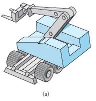
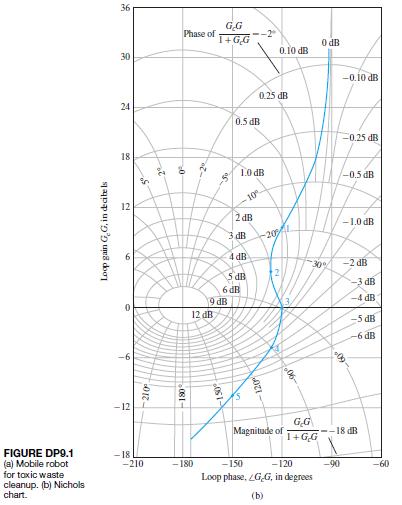
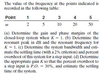
A mobile robot for toxic waste cleanup is shown in Figure DP9.1(a) [23]. The closed-loop speed control is a unity feedback system. The Nichols chart in Figure DP9.1(b) shows the plot of Gc1jv2G1jv2>K versus v. (a)
The system of Figure CDP4.1 uses a controller Gc1s2 = Ka. Determine the value of Ka so that the phase margin is P.M. = 70. Plot the response of this system to a step input. Controller R(s) G(s) FIGURE CDP4.1 The model of the feedback system T(5) Motor and slide G(s) with a capacitance measurement
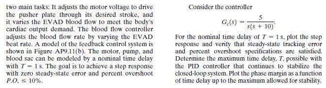
Patients with a cardiological illness and less than normal heart muscle strength can benefit from an assistance device. An electric ventricular assist device(EVAD) converts electric power into blood flow by moving a pusher plate against a flexible blood sac. The pusher plate reciprocates to eject
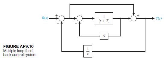
A multiloop block diagram is shown in Figure AP9.10.(a) Compute the transfer function T1s2 = Y1s2>R1s2.(b) Determine K such that the steady-state tracking error to a unit step input R1s2 = 1>s is zero. Plot the unit step response.(c) Using K from part (b), compute the system bandwidth vb.
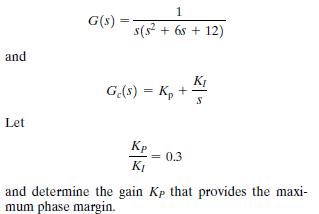
AP9.9 Consider a unity feedback system with and G(s) = 1 s(s +65 +12) Ge(s) = Kp + K S Let Kp 0.3 KI and determine the gain Kp that provides the maxi- mum phase margin.
A control system is shown in Figure AP9.8. The gain K is greater than 500 and less than 4000. Select a gain that will cause the system step response to have a percent overshoot of P.O. … 20,. Plot the Nichols chart and calculate the phase margin. FIGURE AP9.8 Gain selection. R(s) K(s+1)2
Building elevators are limited to about 800 meters.Above that height, elevator cables become too thick and too heavy for practical use. One solution is to eliminate the cable. The key to the cordless elevator is the linear motor technology now being applied to the development of magnetically
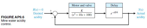
The acidity of water draining from a coal mine is often controlled by adding lime to the water. A valve controls the lime addition and a sensor is downstream.For the model of the system shown in Figure AP9.6, determine K and the distance D to maintain stability.We require D 7 2 meters in order to
A unity feedback control system given by = L(s) G(s) H(s) - Se-st = s(s+3)(s + 4) Determine (a) phase margin for T = 0, (b) limiting value of 7 for stability
The loop transfer function of a system is described as == L(s) = G(s)H(s) = K s(s + 2.45)3 Find the value of K for marginal stability. Find the gain margin and the phase margin for K = 22 and K = 42.
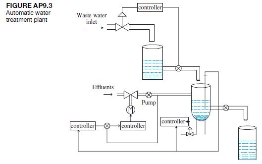
AP9.3 Figure AP9.3 shows an automatic water treatment plant. It is typically a mechanical–chemical arrangement that uses reagent to purify water. The plant comprises an input pipeline embedded with a flow meter and sensors. The temperature and the flow rate of the boiler and the cooling water are
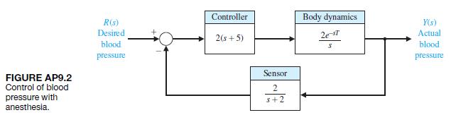
AP9.2 Anesthesia is used in surgery to induce unconsciousness.One problem with drug-induced unconsciousness is differences in patient responsiveness.Furthermore, the patient response changes during an operation. A model of drug-induced anesthesia control is shown in Figure AP9.2. The proxy for
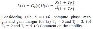
For positive constants of K, T1, and T2, a control system is described by its loop transfer function asConsidering gain K = 0.06, compute phase margin and gain margin for (a) T1 = 5 and T2 = 2. (b)T1 = 2 and T2 = 5. (c) Comment on the stability L(s) = Gc(s)H(s) K(1 + Ts) = s(1 + Ts) Considering
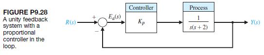
P9.28 Consider the feedback system shown in Figure P9.28.(a) Determine the value of Kp so that the phase margin is P.M. = 60.(b) Using the P.M. obtained to predict the percentage overshoot of the closed-loop system to a unit step input.(c) Plot the step response and compare the actual percent
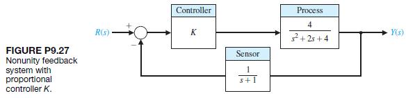
P9.27 Consider the system shown in Figure P9.27.Determine the maximum value of K = Kmax for which the closed-loop system is stable. Plot the phase margin as a function of the gain 1 … K … Kmax. Explain what happens to the phase margin as K approaches Kmax. FIGURE P9.27 Nonunity feedback system
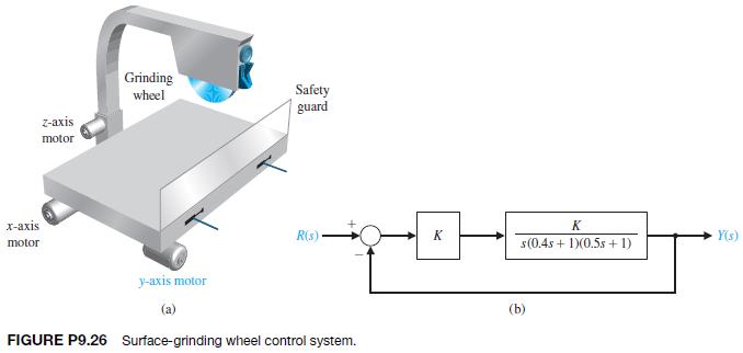
P9.26 A specialty machine shop is improving the efficiency of its surface-grinding process [21]. The existing machine is mechanically sound, but manually operated. Automating the machine will free the operator for other tasks and thus increase overall throughput of the machine shop. The grinding
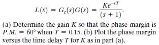
P9.25 A closed loop system has the loop transfer function L(s) = Ge(s)G(s) = Ke-st (s+1) (a) Determine the gain K so that the phase margin is P.M. = 60 when T = 0.15. (b) Plot the phase margin versus the time delay 7 for K as in part (a).
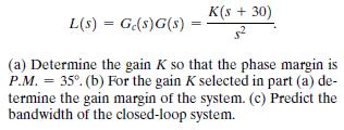
P9.24 A closed-loop system with unity feedback has a loop transfer function K(s + 30) L(s) = Ge(s)G(s) = (a) Determine the gain K so that the phase margin is P.M. =35. (b) For the gain K selected in part (a) de- termine the gain margin of the system. (c) Predict the bandwidth of the closed-loop
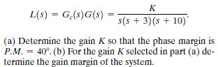
P9.23 A closed-loop system has a loop transfer function(a) Determine the gain K so that the phase margin is P.M. = 40. (b) For the gain K selected in part (a) determine the gain margin of the system. K = L(s) G(s)G(s) = = s(s+3)(s + 10) (a) Determine the gain K so that the phase margin is P.M. 40.
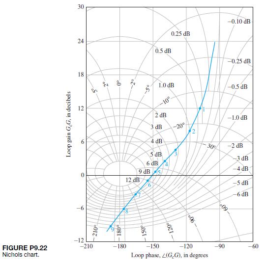
P9.22 The Nichols chart for Gc1jv2G1jv2 of a closed-loop system is shown in Figure P9.22. The frequency for each point on the graph is given in the following table:Determine (a) the resonant frequency, (b) the bandwidth, (c) the phase margin, and (d) the gain margin.(e) Estimate the overshoot and
P9.21 Consider a unity feedback system with the loop transfer function (a) Sketch the Bode plot for K = 4. Determine (b) the gain margin, (c) the value of K required to provide a gain margin equal to 12 dB, and (d) the value of K to yield a steady-state error of 25% of the magnitude A for the ramp
P9.20 The Bell-Boeing V-22 Osprey Tiltrotor is both an airplane and a helicopter. Its advantage is the ability to rotate its engines to a vertical position, as shown in Figure P7.33(a), for takeoffs and landings and then switch the engines to a horizontal position for cruising as an airplane. The
P9.19 In the United States, billions of dollars are spent annually for solid waste collection and disposal.One system, which uses a remote control pick-up arm for collecting waste bags, is shown in Figure P9.19. The loop transfer function of the remote pick-up arm is (a) Plot Nichols chart and show
P9.18 A model of an automobile driver attempting to steer a course is shown in Figure P9.18, where K = 6.0. (a) Find the frequency response and the gain and phase margins when the reaction time T = 0.(b) Find the phase margin when the reaction time is T = 0.15 s. (c) Find the reaction time that
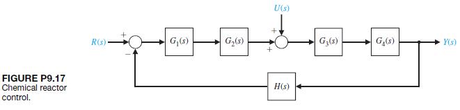
P9.17 The primary objective of many control systems is to maintain the output variable at the desired or reference condition when the system is subjected to a disturbance [22]. A typical chemical reactor control scheme is shown in Figure P9.17. The disturbance is represented by U1s2, and the
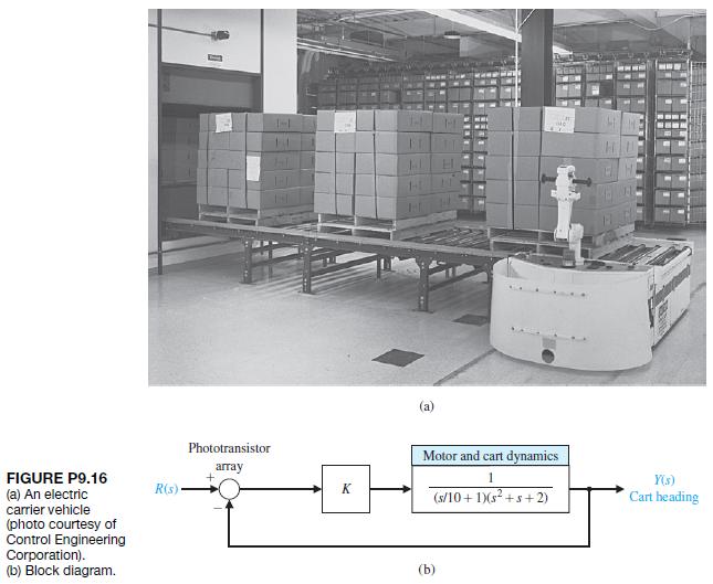
P9.16(a) [15]. Closed-loop feedback systems are used to control the guidance and speed of the vehicle. The cart senses the tape path by means of an array of 16 phototransistors. The block diagram of the steering system is shown in Figure P9.16(b). Select a gain K so that the phase margin is P.M. =
P9.15 Consider the automatic ship-steering system transfer function.The deviation of the tanker from the straight track is measured by radar and is used to generate the error signal, as shown in Figure P9.15. This error signal is used to control the rudder angle d1s2.(a) Is this system stable?
Showing 1 - 100
of 1037
1
2
3
4
5
6
7
8
9
10
11
Step by Step Answers