New Semester
Started
Get
50% OFF
Study Help!
--h --m --s
Claim Now
Question Answers
Textbooks
Find textbooks, questions and answers
Oops, something went wrong!
Change your search query and then try again
S
Books
FREE
Study Help
Expert Questions
Accounting
General Management
Mathematics
Finance
Organizational Behaviour
Law
Physics
Operating System
Management Leadership
Sociology
Programming
Marketing
Database
Computer Network
Economics
Textbooks Solutions
Accounting
Managerial Accounting
Management Leadership
Cost Accounting
Statistics
Business Law
Corporate Finance
Finance
Economics
Auditing
Tutors
Online Tutors
Find a Tutor
Hire a Tutor
Become a Tutor
AI Tutor
AI Study Planner
NEW
Sell Books
Search
Search
Sign In
Register
study help
computer science
modern database management 13th edition
Modern Control Systems 13th Global Edition Robert Bishop Richard Dorf - Solutions
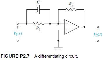
P2.7 Obtain the transfer function of the differentiating circuit shown in Figure P2.7. C R + R + + V(s) FIGURE P2.7 A differentiating circuit. V(s)
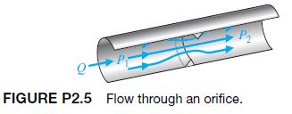
Fluid flowing through an orifice can be represented by the nonlinear equationwhere the variables are shown in Figure P2.5 and K is a constant [2]. (a) Determine a linear approximation for the fluid-flow equation. (b) What happens to the approximation obtained in part (a) if the operating point is
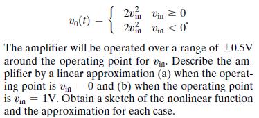
A nonlinear amplifier can be described by the following characteristic: vo(1) 2vin Vin 0 -2v vin
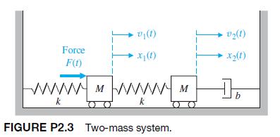
A coupled spring–mass system is shown in Figure P2.3. The masses and springs are assumed to be equal.Obtain the differential equations describing the system. +v(1) Force x (1) V(1) x(1) F(t) wwwMWWW k k FIGURE P2.3 Two-mass system. b
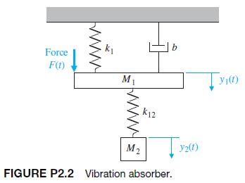
P2.2 A dynamic vibration absorber is shown in Figure P2.2. This system is representative of many situations involving the vibration of machines containing unbalanced components. The parameters M2 and k12 may be chosen so that the main mass M1 does not vibrate in the steady state when F1t2 = a
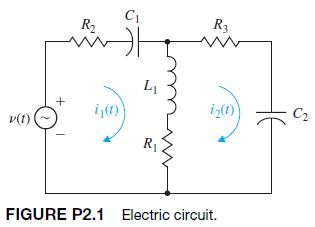
An electric circuit is shown in Figure P2.1. Obtain a set of simultaneous integrodifferential equations representing the network. C R R3 www Li + i(t) 12(1) C v(t) R FIGURE P2.1 Electric circuit.
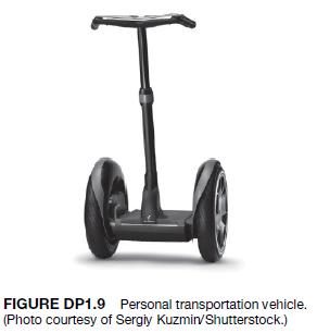
DP1.9 Consider the human transportation vehicle (HTV)depicted in Figure DP1.9. The self-balancing HTV is actively controlled to allow safe and easy transportation of a single person [97]. Describe a closed-loop feedback control system to assist the rider of the HTV in balancing and maneuvering the
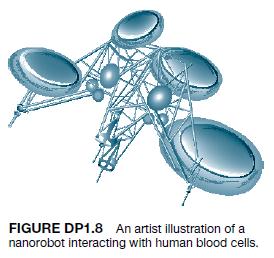
DP1.8 A challenging application of control design is the use of nanorobots in medicine. Nanorobots will require onboard computing capability, and very tiny sensors and actuators. Fortunately, advances in biomolecular computing, bio-sensors, and actuators are promising to enable medical nanorobots
DP1.7 The Hubble space telescope was repaired and modified in space on several occasions [44, 46, 49].One challenging problem with controlling the Hubble is damping the jitter that vibrates the spacecraft each time it passes into or out of the Earth’s shadow. The worst vibration has a period of
DP1.6 Vehicle traction control, which includes antiskid braking and antispin acceleration, can enhance vehicle performance and handling. The objective of this control is to maximize tire traction by preventing locked brakes as well as tire spinning during acceleration.Wheel slip, the difference
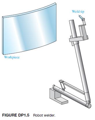
DP1.5 A large, braced robot arm for welding large structures is shown in Figure DP1.5. Sketch the block diagram of a closed-loop feedback control system for accurately controlling the location of the weld tip. Workpiece FIGURE DP1.5 Robot welder. Weld tip
DP1.4 As part of the automation of a dairy farm, the automation of cow milking is under study [36]. Design a milking machine that can milk cows four or five times a day at the cow’s demand. Sketch a block diagram and indicate the devices in each block.
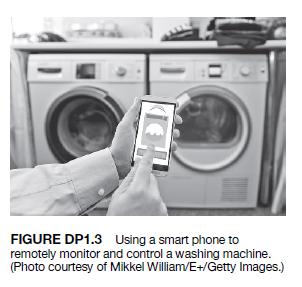
DP1.3 Describe a feedback control system in which a user utilizes a smart phone to remotely monitor and control a washing machine as illustrated in Figure DP1.3. The control system should be able to start and stop the wash cycle, control the amount of detergent and the water temperature, and
DP1.2 Many cars are fitted with cruise control that, at the press of a button, automatically maintains a set speed. In this way, the driver can cruise at a speed limit or economic speed without continually checking the speedometer. Design a feedback-control in block diagram form for a cruise
The road and vehicle noise that invade an automobile’s cabin hastens occupant fatigue [60]. Sketch a block diagram of an “antinoise” feedback system that will reduce the effect of unwanted noises. Indicate the device within each block.
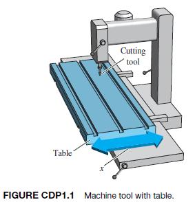
Increasingly stringent requirements of modern, high-precision machinery are placing increasing demands on slide systems [53]. The typical goal is to accurately control the desired path of the table shown in Figure CDP1.1. Sketch a block diagram model of a feedback system to achieve the desired
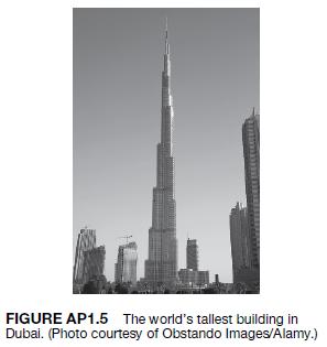
AP1.5 The Burj Dubai is the tallest building in the world[94]. The building, shown in Figure AP1.5, stands at over 800 m with more than 160 stories. There are 57 elevators servicing this tallest free-standing structure in the world. Traveling at up to 10 m/s, the elevators have the world’s
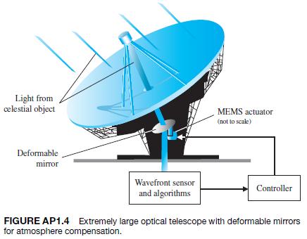
AP1.4 Adaptive optics has applications to a wide variety of key control problems, including imaging of the human retina and large-scale, ground-based astronomical observations [98]. In both cases, the approach is to use a wavefront sensor to measure distortions in the incoming light and to actively
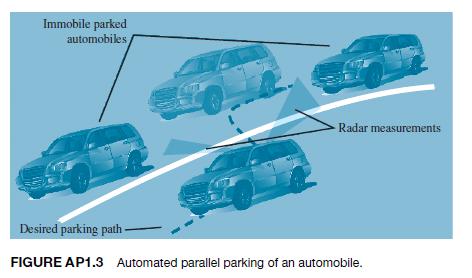
AP1.3 Many modern luxury automobiles have an autopark option. This feature will parallel park an automobile without driver intervention. Figure AP1.3 illustrates the parallel parking scenario. Sketch a block diagram of the automated parallel parking feedback control system. In your own words,
AP1.2 Advanced wind energy systems are being installed in many locations throughout the world as a way for nations to deal with rising fuel prices and energy shortages, and to reduce the negative effects of fossil fuel utilization on the quality of the air. The modern windmill can be viewed as a
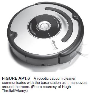
The development of robotic microsurgery devices will have major implications on delicate eye and brain surgical procedures. The microsurgery devices employ feedback control to reduce the effects of the surgeon’s muscle tremors. Precision movements by an articulated robotic arm can greatly help a
P1.27 A direct methanol fuel cell is an electrochemical device that converts a methanol water solution to electricity [75]. Like rechargeable batteries, fuel cells directly convert chemicals to energy; they are very often compared to batteries, specifically rechargeable batteries. However, one
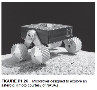
P1.26 NASA is developing a compact rover designed to transmit data from the surface of an asteroid back to Earth, as illustrated in Figure P1.26. The rover will use a camera to take panoramic shots of the asteroid surface. The rover can position itself so that the camera can be pointed straight
P1.25 In the past 50 years, over 20,000 metric tons of hardware have been placed in Earth’s orbit. During the same time span, over 15,000 metric tons of hardware returned to Earth. The objects remaining in Earth’s orbit range in size from large operational spacecraft to tiny flecks of paint.
P1.24 An innovation for an intermittent automobile windshield wiper is the concept of adjusting its wiping cycle according to the intensity of the rain [54]. Sketch a block diagram of the wiper control system.
P1.23 Engineers at the Science University of Tokyo are developing a robot with a humanlike face [52]. The robot can display facial expressions, so that it can work cooperatively with human workers. Sketch a block diagram for a facial expression control system of your own design.
P1.22 Engineers want to design a control system that will allow a building or other structure to react to the force of an earthquake much as a human would. The structure would yield to the force, but only so much, before developing strength to push back [47]. Develop a block diagram of a control
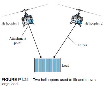
P1.21 The potential of employing two or more helicopters for transporting payloads that are too heavy for a single helicopter is a well-addressed issue in the civil and military rotorcraft design arenas [37]. Overall requirements can be satisfied more efficiently with a smaller aircraft by using
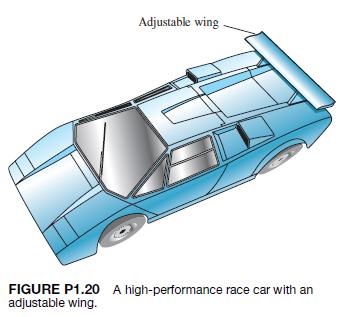
P1.20 A high-performance race car with an adjustable wing (airfoil) is shown in Figure P1.20.Develop a block diagram describing the ability of the airfoil to keep a constant road adhesion between the car’s tires and the race track surface. Why is it important to maintain good road adhesion?
P1.19 Ichiro Masaki of General Motors has patented a system that automatically adjusts a car’s speed to keep a safe distance from vehicles in front. Using a video camera, the system detects and stores a reference image of the car in front. It then compares this image with a stream of incoming
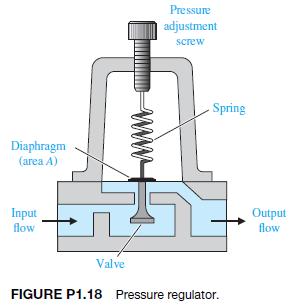
P1.18 A cutaway view of a commonly used pressure regulator is shown in Figure P1.18.The desired pressure is set by turning a calibrated screw. This compresses the spring and sets up a force that opposes the upward motion of the diaphragm. The bottom side of the diaphragm is exposed to the water
P1.17 Baseball players use feedback to judge a fly ball and to hit a pitch [35]. Describe a method used by a batter to judge the location of a pitch so that he can have the bat in the proper position to hit the ball.
P1.16 All humans have experienced a fever associated with an illness. A fever is related to the changing of the control input in the body’s thermostat. This thermostat, within the brain, normally regulates temperature near 98°F in spite of external temperatures ranging from 0°F to 100°F or
P1.15 Small computers are used in automobiles to control emissions and obtain improved gas mileage. A computer-controlled fuel injection system that automatically adjusts the fuel–air mixture ratio could improve gas mileage and reduce unwanted polluting emissions significantly. Sketch a block
P1.14 Adam Smith (1723–1790) discussed the issue of free competition between the participants of an economy in his book Wealth of Nations. It may be said that Smith employed social feedback mechanisms to explain his theories [41]. Smith suggests that (1) the available workers as a whole compare
P1.13 A common example of a two-input control system is a home shower with separate valves for hot and cold water. The objective is to obtain (1) a desired temperature of the shower water and (2) a desired flow of water. Sketch a block diagram of the closed-loop control system.
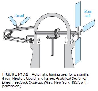
P1.12 An automatic turning gear for windmills was invented by Meikle in about 1750 [1, 11]. The fantail gear shown in Figure P1.12 automatically turns the windmill into the wind. The fantail windmill at right angle to the mainsail is used to turn the turret. The gear ratio is of the order of 3000
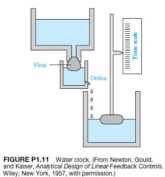
P1.11 Automatic control of water level using a float level was used in the Middle East for a water clock [1, 11].The water clock (Figure P1.11) was used from sometime before Christ until the 17th century. Discuss the operation of the water clock, and establish how the float provides a feedback
P1.10 The role of air traffic control systems is increasing as airplane traffic increases at busy airports. Engineers are developing air traffic control systems and collision avoidance systems using the Global Positioning System (GPS) navigation satellites [34, 55]. GPS allows each aircraft to know
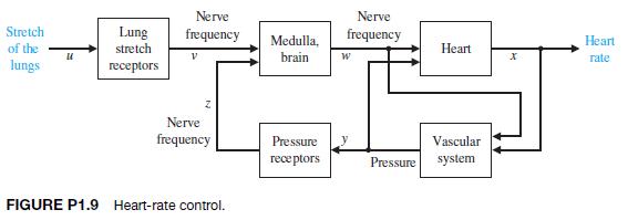
P1.9 Models of physiological control systems are valuable aids to the medical profession. A model of the heartrate control system is shown in Figure P1.9 [23, 48].This model includes the processing of the nerve signals by the brain. The heart-rate control system is, in fact, a multivariable system,
P1.8 The student–teacher learning process is inherently a feedback process intended to reduce the system error to a minimum. Construct a feedback model of the learning process and identify each block of the system.
The story is told about the sergeant who stopped at the jewelry store every morning at nine o’clock and compared and reset his watch with the chronometer in the window. Finally, one day the sergeant went into the store and complimented the owner on the accuracy of the chronometer.“Is it set
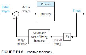
P1.6 Feedback systems do not always involve negative feedback. Economic inflation, which is evidenced by continually rising prices, is a positive feedback system. A positive feedback control system, as shown in Figure P1.6, adds the feedback signal to the input signal, and the resulting signal is
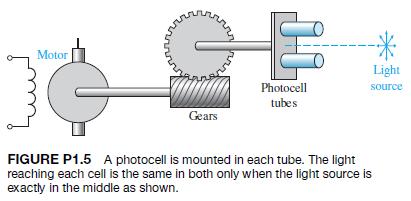
P1.5 A light-seeking control system, used to track the sun, is shown in Figure P1.5. The output shaft, driven by the motor through a worm reduction gear, has a bracket attached on which are mounted two photocells.Complete the closed-loop system so that the system follows the light source. Motor E
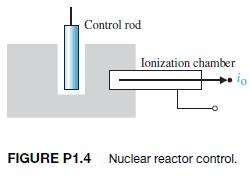
P1.4 The accurate control of a nuclear reactor is important for power system generators. Assuming the number of neutrons present is proportional to the power level, an ionization chamber is used to measure the power level. The current io is proportional to the power level. The position of the
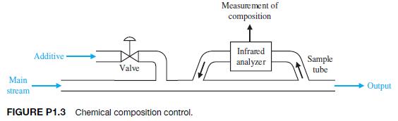
P1.3 In a chemical process control system, it is valuable to control the chemical composition of the product.To do so, a measurement of the composition can be obtained by using an infrared stream analyzer, as shown in Figure P1.3. The valve on the additive stream may be controlled. Complete the
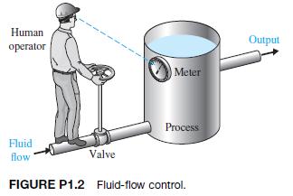
P1.2 Control systems can use a human operator as part of a closed-loop control system. Sketch the block diagram of the valve control system shown in Figure P1.2. Human operator Fluid flow Output Meter Process Valve FIGURE P1.2 Fluid-flow control.
P1.1 Many luxury automobiles have thermostatically controlled air-conditioning systems for the comfort of the passengers. Sketch a block diagram of an air-conditioning system where the driver sets the desired interior temperature. Identify the function of each element of the thermostatically
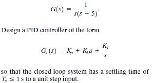
A unity feedback control system has the plant transfer function G(s) = 1 s(s-5) Design a PID controller of the form Gc(s) = K+Kps + K S so that the closed-loop system has a settling time of T, 1s to a unit step input.
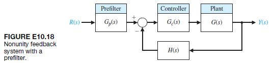
E10.18 The nonunity feedback control system shown in Figure E10.18 has the transfer functions FIGURE E10.18 Nonunity feedback system with a prefilter. Prefilter Controller Plant R(s) Gp(s) Ge(s) G(s) Y(s) H(s)
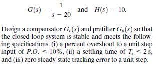
Consider again the system of Exercise 10.9. Select KP and KI so that the step response is deadbeat and the settling time (with a 2% criterion) is Ts … 2 s.Data from in E10.9 A control system with a controller is shown in Figure E10.9. Select KP and KI so that the percent overshoot to a step input
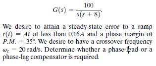
A unity feedback control system has a plant transfer function = = G(s) = 100 s(s + 8) We desire to attain a steady-state error to a ramp r(t) At of less than 0.16A and a phase margin of P.M. 35. We desire to have a crossover frequency 20 rad/s. Determine whether a phase-lad or a phase-lag
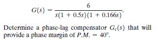
E10.14 A robot will be operated by NASA to build a permanent lunar station. The unity feedback position control system for the gripper tool has the process transfer function 6 G(s) = s(1+0.5s) (1+0.1665)* Determine a phase-lag compensator Ge(s) that will provide a phase margin of P.M. = 40.
The design of Example 10.3 determined a lead network in order to obtain desirable dominant root locations using a cascade compensator Gc1s2 in the system configuration shown in Figure 10.1(a). The same lead network would be obtained if we used the feedback compensation configuration of Figure
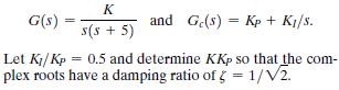
The control of an automobile ignition system has unity feedback and a loop transfer function L1s2 =Gc1s2G1s2, where K G(s) = s(s + 5) and Ge(s) Kp + K/s. = Let Ki/Kp = 0.5 and determine KKp so that the com- plex roots have a damping ratio of 1/2. =
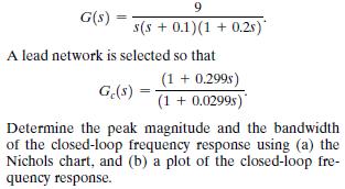
E10.11 A unity feedback system has G(s) = 9 s(s +0.1)(1+0.2s)* A lead network is selected so that Ge(s) = (1 + 0.2998) (1+0.0299s)" Determine the peak magnitude and the bandwidth of the closed-loop frequency response using (a) the Nichols chart, and (b) a plot of the closed-loop fre- quency
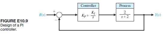
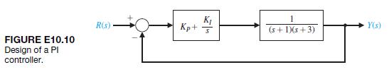
A control system with a controller is shown in Figure E10.10. Select KI = 2 in order to provide a reasonable steady-state error to a step [8]. Find KP to obtain a phase margin of P.M. = 60°. Find the peak time and percent overshoot of this system. FIGURE E10.10 Design of a PI controller. K R(s) Kp
A control system with a controller is shown in Figure E10.9. Select KP and KI so that the percent overshoot to a step input is P.O. = 4,, and the velocity constant Kv is equal to 10. Verify the results of your design. Controller Process K 2 R(s) Kp+ Y(s) s+2 FIGURE E10.9 Design of a PI controller.
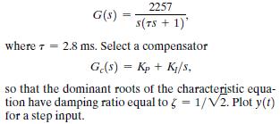
A unity feedback system has a plant G(s) = 2257 S(TS+1)' where = 2.8 ms. Select a compensator Ge(s) = Kp + K/s, so that the dominant roots of the characteristic equa- tion have damping ratio equal to 5 = 1/V2. Plot y(t) for a step input.
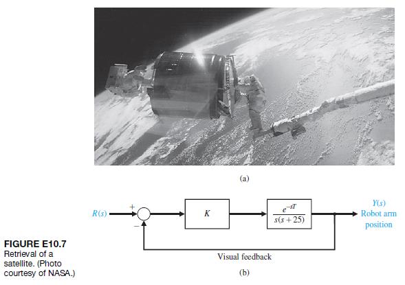
NASA astronauts retrieved a satellite and brought it into the cargo bay of the space shuttle, as shown in Figure E10.7(a). A model of the feedback control system is shown in Figure E10.7(b). Determine the value of K that will result in a phase margin of P.M. = 40°when T = 0.6 s. FIGURE E10.7
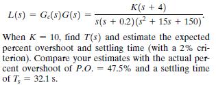
Consider the system with the loop transfer functions = L(s) Ge(s)G(s) = K(s + 4) s(s + 0.2)(s + 15s + 150)* When K = 10, find T(s) and estimate the expected percent overshoot and settling time (with a 2% cri- terion). Compare your estimates with the actual per- cent overshoot of P.O. = 47.5% and a
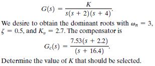
Consider a unity feedback system with the transfer function K G(s) = s(s + 2)(s + 4) We desire to obtain the dominant roots with w * = 0.5, and K, = 2.7. The compensator is 7.53(s + 2.2) = 3. Ge(s)- (5 + 16.4) Determine the value of K that should be selected.
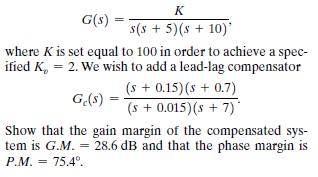
Consider a unity feedback system with G(s) = K s(s + 5)(s + 10)' where K is set equal to 100 in order to achieve a spec- ified K,, = 2. We wish to add a lead-lag compensator (s + 0.15)(s + 0.7) Ge(s) = (s + 0.015)(s +7) Show that the gain margin of the compensated sys- tem is G.M. = 28.6 dB and
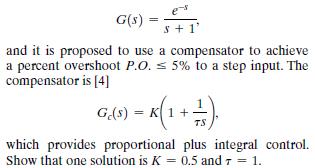
E10.3 A unity feedback control system in a manufacturing system has a process transfer function G(s) = 1 s+1' and it is proposed to use a compensator to achieve a percent overshoot P.O. < 5% to a step input. The compensator is [4] G.(S) = K(1+1). TS which provides proportional plus integral
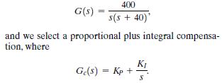
A control system with negative unity feedback has a processNote that the steady-state error of this system for a ramp input is zero. (a) Set KI = 1 and find a suitable value of KP so the step response will have a percent overshoot of P.O. … 20,. (b) What is the expected settling time (with a 2%
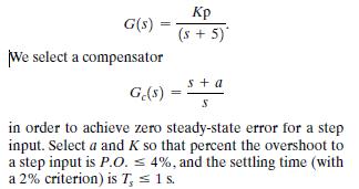
A negative feedback control system has a transfer function G(s) = We select a compensator ($+5)* s+a Ge(s) = S in order to achieve zero steady-state error for a step input. Select a and K so that percent the overshoot to a step input is P.O. 4%, and the settling time (with a 2% criterion) is T, 1
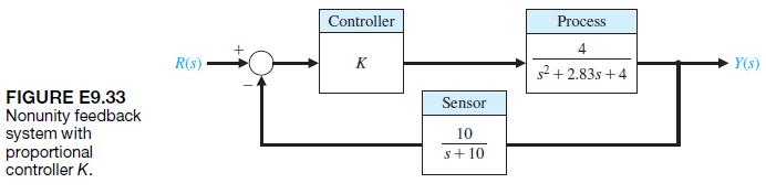
E9.33 Consider the system shown in Figure E9.33.Compute the loop transfer function L1s2, and sketch the Bode plot. Determine the phase margin and gain margin when the controller gain K = 5. FIGURE E9.33 Nonunity feedback system with proportional controller K. Controller R(s) K Sensor 10 s+10
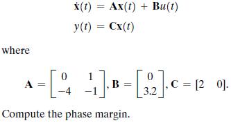
E9.32 Consider the system described in state variable form by where x(t) = Ax(t) + Bu(t) y(t) = Cx(t) A 0 - [14 11]. B = [3,2]. C = 12 0]. -4 Compute the phase margin.
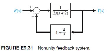
E9.31 A closed-loop feedback system is shown in Figure E9.31. Sketch the Bode plot and determine the phase margin. R(s) 1 2s(s+2) 4 1+ 1 S FIGURE E9.31 Nonunity feedback system. Y(s)
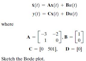
E9.30 A system is represented in state variable form where == x(t) = Ax(t) + Bu(t) y(t)=Cx(t) + Du(t) -3 == C = [0_501], D = [0] Sketch the Bode plot.
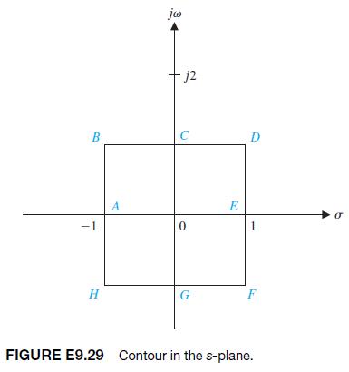
E9.29 A loop transfer function isUsing the contour in the s-plane shown in Figure E9.29, determine the corresponding contour in the F1s2-plane 1B = -1 + j2. L(s) = Ge(s)G(s) === 1 $ +2
E9.28 A unity feedback system has the loop transfer function(a) Determine the phase gain for the system. (b) Use the phase margin to estimate the damping ratio and predict the percentage overshoot. (c) Calculate the actual response for this system and compare the result with the part (b) estimate.
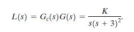
E9.27 A unity feedback system has a loop transfer function(a) Determine the maximum gain K for which the phase margin is P.M. Ú 30 and the gain margin is G.M. = 8 dB. (b) Determine the value of gain K and cross over frequency for marginal stability. L(s)G(s)G(s) = K s(5 + 3)
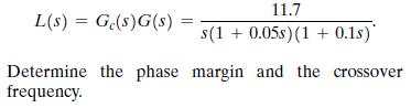
E9.26 For the system of E9.25, determine Mpv, vr, and vB for the closed-loop frequency response by using the Nichols chart.Data from in E9.25A unity feedback system has a loop transfer function 11.7 L(s) = Ge(s)G(s) = s(1+0.05s) (1+0.1s)* Determine the phase margin and the crossover frequency.
E9.25 A unity feedback system has a loop transfer function 11.7 L(s) = Ge(s)G(s) = s(1+0.05s) (1+0.1s)* Determine the phase margin and the crossover frequency.
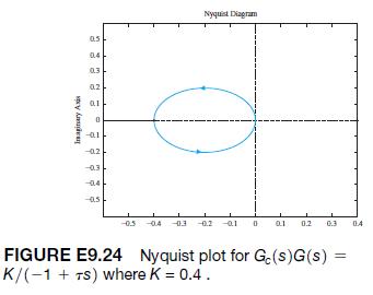
E9.24 A unity feedback system has a loop transfer functionwhere K = 0.4 and t = 1. The Nyquist plot for Gc1jv2G1jv2 is shown in Figure E9.24. Determine whether the system is stable by using the Nyquist criterion. K L(s) = Ge(s)G(s) (-1+75)
E9.23 Consider again the system of E9.21 when K = 100.Determine the closed-loop system bandwidth, resonant frequency, and Mpv.Data from in E9.21 A unity feedback control system has a loop transfer functionDetermine the phase margin, the crossover frequency, and the gain margin when K = 1300. K L(s)
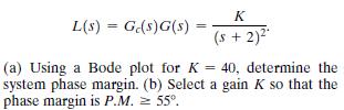
E9.22 A unity feedback system has a loop transfer function K L(s) = Gc(s)G(s) = (s + 2) (a) Using a Bode plot for K = 40, determine the system phase margin. (b) Select a gain K so that the phase margin is P.M. = 55.
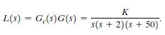
E9.21 A unity feedback control system has a loop transfer functionDetermine the phase margin, the crossover frequency, and the gain margin when K = 1300. K L(s) = Ge(s)G(s) s(s+2)(s+50)
E9.20 Consider a simple model of an automobile driver following another car on the highway at high speed.The model shown in Figure E9.20 incorporates the driver’s reaction time, T. One driver has T = 1 s, and another has T = 1.5 s. Determine the time response y1t2 of the system for both drivers
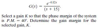
E9.19 A unity feedback system with Gc1s2 = K has G(s) = = e-0.12s (s +15) Select a gain K so that the phase margin of the system is P.M. =40. Determine the gain margin for the selected gain, K.
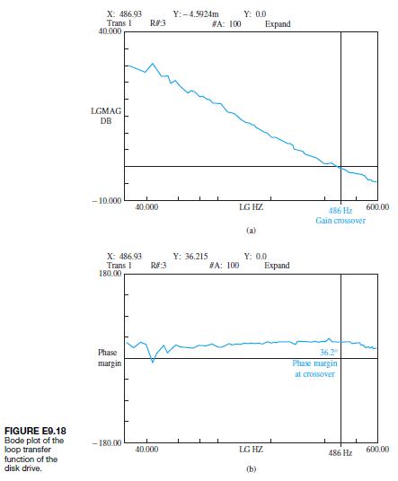
E9.18 An actuator for a disk drive uses a shock mount to absorb vibrational energy at approximately 60 Hz [14]. The Bode plot of the loop transfer function of the control system is shown in Figure E9.18. (a) Find the expected percent overshoot for a step input for the closed-loop system, (b)
E9.17 A unity feedback system has a loop transfer function(a) Obtain the Bode plot and (b) determine the gain K required to obtain a phase margin of P.M. = 56.What is the steady-state error for a ramp input for the gain of part (b)? Ge(s)G(s) K(s + 4) s(s + 3s+20)
E9.16 The pure time delay e-sT may be approximated by a transfer function asObtain the Bode plot for the actual transfer function and the approximation for T = 0.2 for 0 6 v 6 10. e-st -ST R 1- Ts/2 1+ Ts/2
E9.15 Consider a unity feedback system with the loop transfer functionFind the bandwidth of the closed-loop system. 100 L(s) = Ge(s)G(s) s(s +20)
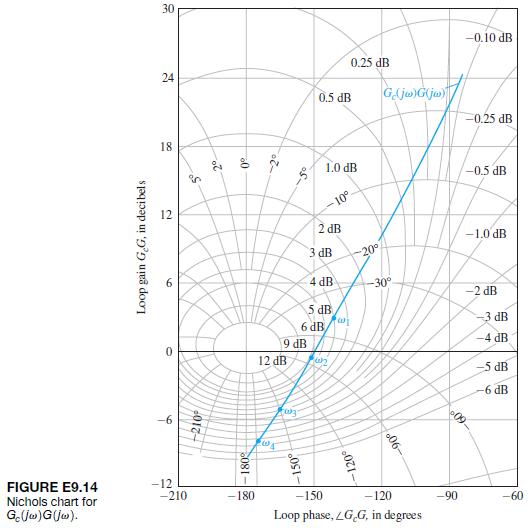
E9.14 A Nichols chart is given in Figure E9.14 for a system with Gc1jv2G1jv2. Using the following table, find(a) the peak resonance Mpv in dB; (b) the resonant frequency vr; (c) the 3-dB bandwidth; and (d) the phase margin of the system. Loop gain GG, in decibels -6 2 18 24 5 S 30 2 0 2 S 5 0.5 dB
E9.13 A unity feedback system has a loop transfer function(a) Find the maximum magnitude of the closed-loop frequency response. (b) Find the bandwidth and the resonant frequency of this system. (c) Use these frequency measures to estimate the overshoot of the system to a step response. G(s)G(s) 200
E9.12 A unity feedback system with the loop transfer functionwhere t1 = 0.01 and t2 = 0.3 s. (a) Select a gain K so that the steady-state error for a ramp input is 20% of the magnitude of the ramp function A, where r1t2 = A1t2, t Ú 0. (b) Obtain the Bode plot of loop transfer function, and
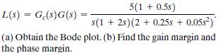
E9.11 Consider a unity feedback system with the loop transfer function 5(1 + 0.5s) = L(s) G(s)G(s) = = s(1+2s) (2 +0.25s + 0.05s) (a) Obtain the Bode plot. (b) Find the gain margin and the phase margin.
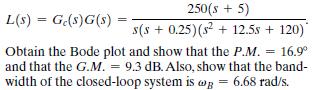
E9.10 Consider a system with the loop transfer function L(s) = Ge(s)G(s) = 250(s + 5) s(s+ 0.25)(s+12.5s + 120) Obtain the Bode plot and show that the P.M. = 16.9 and that the G.M. = 9.3 dB. Also, show that the band- width of the closed-loop system is wg = 6.68 rad/s.
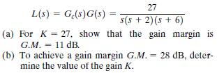
E9.9 For the system of E9.8, find the phase margin of the system for K = 5.Data from in E9.8 Consider a unity feedback with the loop transfer function 27 = L(s) G(s)G(s) = s(s + 2)(s + 6) (a) For K27, show that the gain margin is G.M. = 11 dB. (b) To achieve a gain margin G.M. = 28 dB, deter- mine
E9.8 Consider a unity feedback with the loop transfer function 27 = L(s) G(s)G(s) = s(s + 2)(s + 6) (a) For K27, show that the gain margin is G.M. = 11 dB. (b) To achieve a gain margin G.M. = 28 dB, deter- mine the value of the gain K.
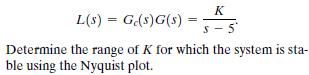
E9.7 A unity feedback system has a loop transfer function K L(s) = Ge(s)G(s) = S-5 Determine the range of K for which the system is sta- ble using the Nyquist plot.
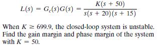
E9.6 A system has a loop transfer function L(s) = Ge(s)G(s) = K(s + 50) s(s +20) (s +15) When K 699.9, the closed-loop system is unstable. Find the gain margin and phase margin of the system with K = 50.
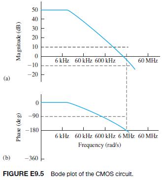
E9.5 An integrated CMOS digital circuit can be represented by the Bode plot shown in Figure E9.5. (a) Find the gain and phase margins of the circuit. (b) Estimate how much we would need to reduce the system gain(dB) to obtain a phase margin of P.M. = 60o. (a) Phase (deg) Magnitude (dB) 50 40 30 20
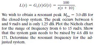
E9.4 Consider a system with a loop transfer function 100 L(s) = Ge(s)G(s) = s(s + 10) We wish to obtain a resonant peak Mp = 3.0 dB for the closed-loop system. The peak occurs between 6 and 9 rad/s and is only 1.25 dB. Plot the Nichols chart for the range of frequency from 6 to 15 rad/s. Show that
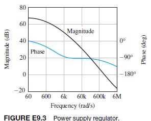
E9.3 An integrated circuit is available to serve as a feedback system to regulate the output voltage of a power supply. The Bode plot of the loop transfer function is shown in Figure E9.3 Estimate the phase margin of the regulator. 80 50 60 60 Magnitude (dB) 40 20 Phase Magnitude 0 -90 -180 0 -20
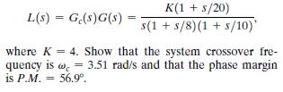
E9.2 A system has the loop transfer function K(1 + s/20) L(s) = G(s)G(s) = s(1+s/8)(1 + 5/10)' where K 4. Show that the system crossover fre- quency is w=3.51 rad/s and that the phase margin is P.M. = 56.9
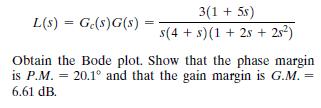
E9.1 A system has the open loop transfer function L(s) = Ge(s)G(s) = 3(1 + 5s) s(4+s) (1+2s+ 2s) Obtain the Bode plot. Show that the phase margin is P.M. = 20.1 and that the gain margin is G.M. = 6.61 dB.
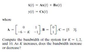
Consider the single-input, single-output system described by where x(t) =Ax(t) + Bu(t) y(t) = Cx(1) --- 15 31. -6-K Compute the bandwidth of the system for K = 1.2. and 10. As K increases, does the bandwidth increase or decrease?
Showing 300 - 400
of 1037
1
2
3
4
5
6
7
8
9
10
11
Step by Step Answers