New Semester
Started
Get
50% OFF
Study Help!
--h --m --s
Claim Now
Question Answers
Textbooks
Find textbooks, questions and answers
Oops, something went wrong!
Change your search query and then try again
S
Books
FREE
Study Help
Expert Questions
Accounting
General Management
Mathematics
Finance
Organizational Behaviour
Law
Physics
Operating System
Management Leadership
Sociology
Programming
Marketing
Database
Computer Network
Economics
Textbooks Solutions
Accounting
Managerial Accounting
Management Leadership
Cost Accounting
Statistics
Business Law
Corporate Finance
Finance
Economics
Auditing
Tutors
Online Tutors
Find a Tutor
Hire a Tutor
Become a Tutor
AI Tutor
AI Study Planner
NEW
Sell Books
Search
Search
Sign In
Register
study help
computer science
modern database management 13th edition
Modern Control Systems 13th Global Edition Robert Bishop Richard Dorf - Solutions
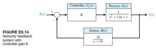
E8.14 Consider the nonunity feedback system in Figure E8.14, where the controller gain is K = 2.Sketch the Bode plot of the loop transfer function. Determine FIGURE E8.14 Nonunity feedback system with controller gain K. R(s) Controller, G(s) K Process, G(s) 1 s+1.45+1 Sensor, H(s) 10 s+10 Y(s)
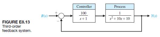
E8.13 Determine the bandwidth of the feedback control system in Figure E8.13. FIGURE E8.13 Third-order feedback system. Controller Process 100 1 R(s) Y(s) s+1 s+10s+10
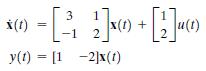
E8.12 Consider the system represented in state variable form(a) Determine the transfer function representation of the system. (b) Sketch the Bode plot. x(t) 1 [32]00+ [2] y(t) = [12]x(t)
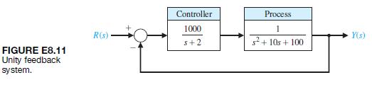
E8.11 Consider the feedback control system in Figure E8.11. Sketch the Bode plot of G1s2 and determine the crossover frequency, that is, the frequency when 20 log10 G1jv2 = 0 dB. Controller 1000 R(s) 5+2 FIGURE E8.11 Unity feedback system. Process 1 s+ 10s +100 Y(s)
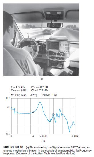
E8.10 The dynamic analyzer shown in Figure E8.10(a)can be used to display the frequency response of a system. Also shown is the signal analyzer used to measure the mechanical vibration in the cockpit of an automobile. Figure E8.10(b) shows the actual frequency response of a system. Estimate the
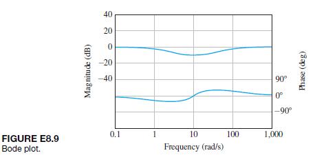
E8.9 The Bode plot of a system is shown in Figure E8.9.Estimate the transfer function G1s2. FIGURE E8.9 Bode plot. Magnitude (dB) 40 20 0 -20 -40 0.1 1 10 Frequency (rad/s) 90 0 -90 100 1,000 Phase (deg)
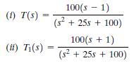
For each of the transfer function, determine (a) Break frequencies for the Bode plot. (b) The slope of the asymptotic plot at very low frequencies and at high frequencies. (c) Sketch the Bode magnitude plot and compare them.
The two feedback systems with respective loop transfer function are represented as: 100(S-1) (s +255 + 100) (52 100(s + 1) (s + 25s + 100) (i) T(s) (52 (ii) T(s)
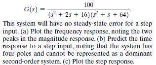
Consider a system with a closed-loop transfer function G(s) = 100 (s+2s+16) (s + s + 64)* This system will have no steady-state error for a step input. (a) Plot the frequency response, noting the two peaks in the magnitude response. (b) Predict the time response to a step input, noting that the
Several studies have proposed an extravehicular robot that could move around in a NASA space station and perform physical tasks at various worksites[9]. The arm is controlled by a unity feedback control with loop transfer function K = L(s) Ge(s)G(s) = = s(s/8 + 1)(s/120 +1)* Sketch the Bode plot
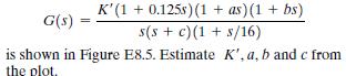
The magnitude plot of a transfer function G(s) K' (1+0.125s)(1 + as) (1 + bs) s(s + c)(1 + s/16) is shown in Figure E8.5. Estimate K', a, b and c from the plot.
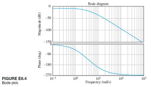
The frequency response for the system G(s) = Ks (sa)(s + 5s + 6.25) is shown in Figure E8.4. Estimate K and a by examin- ing the frequency response curves.
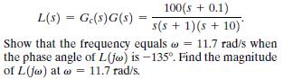
A robotic arm has a joint-control loop transfer function L(s) = Ge(s)G(s) = 100(s + 0.1) s(s + 1)(s + 10)* Show that the frequency equals 11.7 rad/s when the phase angle of L(jw) is -135. Find the magnitude of L(jw) at w 11.7 rad/s.
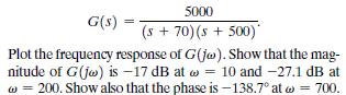
A tendon-operated robotic hand can be implemented using a pneumatic actuator [8].The actuator can be represented by G(s) = 5000 (s + 70) (s +500)* Plot the frequency response of G(jo). Show that the mag- nitude of G(jw) is -17 dB at 10 and -27.1 dB at 200. Show also that the phase is -138.7 at w =
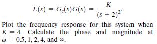
Increased track densities for computer disk drives necessitate careful design of the head positioning control[1]. The loop transfer function is == == L(s) G(s)G(s) = K (s + 2) Plot the frequency response for this system when K = 4. Calculate the phase and magnitude at w=0.5, 1, 2, 4, and 0.
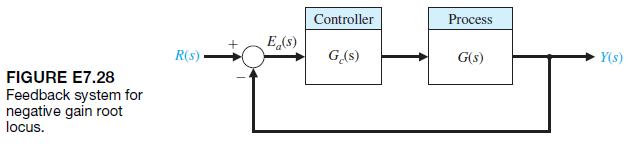
E7.28 Consider the feedback system in Figure E7.28.Obtain the negative gain root locus as -∞ 6 K … 0.For what values of K is the system stable? Controller Process Ea(s) R(s) Ge(s) G(s) Y(s) FIGURE E7.28 Feedback system for negative gain root locus.
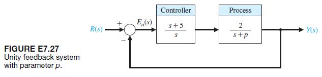
E7.27 Consider the unity feedback system in Figure E7.27. Sketch the root locus as 0 … p 6 ∞. FIGURE E7.27 Unity feedback system with parameter p. Controller Process E(s) S+5 2 R(s) Y(s) S s+p
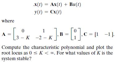
E7.26 Consider the single-input, single-output system is described by where x(t) = Ax(t) + Bu(t) y(t) = Cx(t) A = [3 K 0 1 K] B = [] C = [1 1]. 3-K-2-K Compute the characteristic polynomial and plot the root locus as 0 < K < . For what values of K is the system stable?
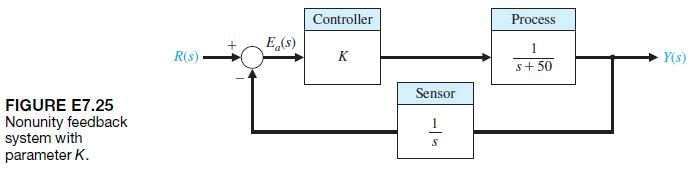
E7.25 A closed-loop feedback system is shown in Figure E7.25. For what range of K is the system stable?Sketch the root locus as 0 6 K 6 ∞. FIGURE E7.25 Nonunity feedback system with parameter K. R(s) E(s) Controller K Sensor HP Process 1 s+50 Y(s)
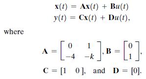
Consider the system represented in state variable formDetermine the characteristic equation and then sketch the root locus as 0 6 k 6 ∞. where A = = x(t) Ax(t) + Bu(t) y(t) =Cx(t) + Du(t), 0 1 [14 -k C [10], and D = [0].
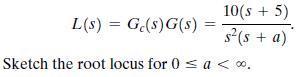
A unity feedback system has a loop transfer function L(s) = G(s)G(s) 10(s + 5) s(s + a) Sketch the root locus for 0 < a < .
A high-performance missile for launching a satellite has a unity feedback system with a loop transfer function L(s) = Ge(s)G(s) = K(s + 18)(s + 2) (s2-2) (s +12) Sketch the root locus as K varies from 0 < K < .
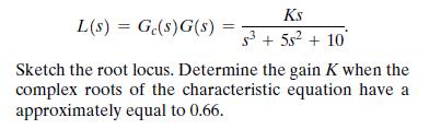
A unity feedback system has a loop transfer function Ks L(s) = Ge(s)G(s) = $3+5s+10 Sketch the root locus. Determine the gain K when the complex roots of the characteristic equation have a approximately equal to 0.66.
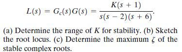
A unity feedback system has a loop transfer function L(s) = Ge(s)G(s) K(s + 1) s(s - 2)(s + 6) (a) Determine the range of K for stability. (b) Sketch the root locus. (c) Determine the maximum stable complex roots. of the
A unity feedback system has a loop transfer function L(s) = Ge(s)G(s) = K s(s+3) (s + 6s+64)* (a) Determine the angle of departure of the root locus at the complex poles. (b) Sketch the root locus. (c) Determine the gain K when the roots are on the jw-axis and determine the location of these roots.
A closed-loop negative unity feedback system is used to control the yaw of an aircraft. When the loop transfer function is L(s) = Ge(s)G(s) = K s(s+3)(s+2s+ 2)' determine (a) the root locus breakaway point and (b) the value of the roots on the jo-axis and the gain required for those roots. Sketch
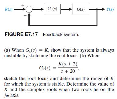
A control system, as shown in Figure E7.17, has a process G(s) = 1 s(S-1)
A negative unity feedback system has a loop transfer function L(s) = Ge(s)G(s) == Ke-ST S+1' where T=0.1 s. Show that an approximation for the time delay is 2 S T e-st 2 + S Using e-0.15 20-s 20+ s' obtain the root locus for the system for K > 0. Determine the range of K for which the system is
(a) Plot the root locus for a unity feedback system with loop transfer function K(s + 10) (s + 2) = L(s) Ge(s)G(s) = (b) Calculate the range of K for which the system is stable. (c) Predict the steady-state error of the system for a ramp input.
A unity feedback system has the loop transfer function+ K(s + 15) L(s) = Ge(s)G(s) s(s+3) (a) Determine the breakaway and entry points of the root locus and sketch the root locus for K > 0. (b) Determine the gain K when the two characteristic roots have a 5 of 1/V2. (c) Calculate the roots.
A unity feedback system has a loop transfer function L(s) = Ge(s)G(s) = 4(s + z) s(s + 1)(s + 3) (a) Draw the root locus as z varies from 0 to 100. (b) Using the root locus, estimate the percent overshoot and settling time (with a 2% criterion) of the system at z = 0.6, 2, and 4 for a step input.
A unity feedback system has a loop transfer function L(s) = KG(s) = K(s + 1) s(s + 6s+18) (a) Sketch the root locus for K > 0. (b) Find the roots when K = 10 and 20. (c) Compute the rise time, percent overshoot, and settling time (with a 2% criterion) of the system for a unit step input when K = 10
A robot force control system with unity feedback has a loop transfer function [6] L(s) = KG(s) = K(s + 2.5) (s2 +25+2)(s2 + 4s +5)* (a) Find the gain K that results in dominant roots with a damping ratio of 0.707. Sketch the root locus. (b) Find the actual percent overshoot and peak time for the
A unity feedback system has the loop transfer function L(s) = KG(s) K(s + 6) s(s+4)* (a) Find the breakaway and entry points on the real axis. (b) Find the gain and the roots when the real part of the complex roots is located at -3. (c) Sketch the root locus.
The primary mirror of a large telescope can have a diameter of 10 m and a mosaic of 36 hexagonal segments with the orientation of each segment actively controlled. Suppose this unity feedback system for the mirror segments has the loop transfer function K == L(s) = Ge(s)G(s) s(s + 2s + 5) (a) Find
E7.8 Sketch the root locus for a unity feedback system with L(s) = Ge(s)G(s) = K(s + 1) s(s+9) (a) Find the gain when all three roots are real and equal. (b) Find the roots when all the roots are equal as in part (a).
E7.7 The elevator in a modern office building can travel at a speed of 25 feet per second and still stop within one-eighth of an inch of the floor outside. The loop transfer function of the unity feedback elevator position control is K(s + 3) L(s) = Ge(s)G(s) = s(s+1)(s+5)(s + 10)* Determine the
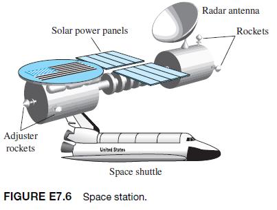
E7.6 One version of a space station is shown in Figure E7.6 [28].It is critical to keep this station in the proper orientation toward the Sun and the Earth for generating power and communications. The orientation controller may be represented by a unity feedback system with an actuator and
E7.5 Consider a unity feedback system with a loop transfer function(a) Find the breakaway point on the real axis. (b) Find the asymptote centroid. (c) Find the value of K at the breakaway point. S+4 L(s) = Ge(s)G(s) 3+10s+25s + 85
Consider a unity feedback system with the loop transfer function(a) Find the angle of departure of the root locus from the complex poles. (b) Find the entry point for the root locus as it enters the real axis. K(s + 5) L(s) = Ge(s)G(s) == s2+12s+8
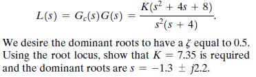
A unity feedback control system for an automobile suspension tester has the loop transfer function [12] L(s) = Ge(s)G(s) K(s + 4s + 8) s(s + 4) We desire the dominant roots to have a 3 equal to 0.5. Using the root locus, show that K = 7.35 is required and the dominant roots are s-1.3 2.2.
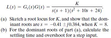
A tape recorder with a unity feedback speed control system has the loop transfer function K L(s) = Ge(s)G(s) s(s+ 1)(s + 10s + 24)* (a) Sketch a root locus for K, and show that the dom- inant roots are s = -0.41 j0.384, when K = 8. (b) For the dominant roots of part (a), calculate the settling time
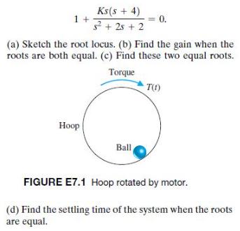
Consider a device that consists of a ball rolling on the inside rim of a hoop [11]. This model is similar to the problem of liquid fuel sloshing in a rocket. The hoop is free to rotate about its horizontal principal axis as shown in Figure E7.1. The angular position of the hoop may be controlled
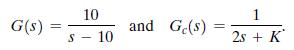
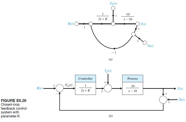
E6.26 Consider the closed-loop system in Figure E6.26, where(a) Determine the characteristic equation associated with the closed-loop system.(b) Determine the values of K for which the closedloop system is stable. 10 1 G(s) and Ge(s) S-10 2s+ K
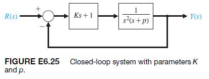
E6.25 A closed-loop feedback system is shown in Figure E6.25. For what range of values of the parameters K and p is the system stable? 1 R(s) Ks+1 s(s+p) Y(s) FIGURE E6.25 Closed-loop system with parameters K and p.
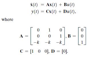
E6.24 Consider the system represented in state variable form(a) What is the system transfer function? (b) For what values of k is the system stable? where x(t) Ax(t) + Bu(t) y(t)=Cx(t) + Du(t), 0 1 0 A 0 0 1, B 0 -k -k -k C [100], D = [0].
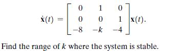
E6.23 The matrix differential equation of a state variable model of a system is 0 1 0 x(t) 0 0 1 x(t). -8 -k-4 Find the range of k where the system is stable.
E6.22 A system has the characteristic equation q(s) = s3 + 10s2 + 29s + K = 0.Shift the vertical axis to the right by 2 by using s =sn - 2, and determine the value of gain K so that the complex roots are s = -2 { j.
E6.21 A system has a transfer function Y1s2>R1s2 =T(s) = 1>s1s + 12. (a) Is this system stable? (b) If r(t) is a unit step input, determine the response y1t2.
E6.20 Find the roots of the following polynomials:(a) s3 + 5s2 + 8s + 4 = 0 and(b) s3 + 9s2 + 27s + 27 = 0.
Determine whether the systems with the following characteristic equations are stable or unstable:(a) s3 + 4s2 + 6s + 100 = 0,(b) s4 + 6s3 + 10s2 + 17s + 6 = 0, and(c) s2 + 6s + 3 = 0.
E6.18 A system has a characteristic equation q1s2 = s3 + 20s2 + 5s + 100 = 0.(a) Determine whether the system is stable, using the Routh–Hurwitz criterion. (b) Determine the roots of the characteristic equation.
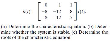
E6.17 The matrix differential equation of a state variable model of a system is x(t) = 0 1 -1 8 x(t). -8-12 -8 -12 5 (a) Determine the characteristic equation. (b) Deter- mine whether the system is stable. (c) Determine the roots of the characteristic equation.
A system has a characteristic equation q1s2 = s5 + 5s4 + 12s3 + 6s2 + 42s + 10 = 0(a) Determine whether the system is stable, using the Routh–Hurwitz criterion. (b) Determine the roots of the characteristic equation.
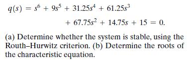
A system has a characteristic equation q(s) s+95 + 31.25s4 + 61.25s = + 67.75s2+14.75s + 15 = 0. (a) Determine whether the system is stable, using the Routh-Hurwitz criterion. (b) Determine the roots of the characteristic equation.
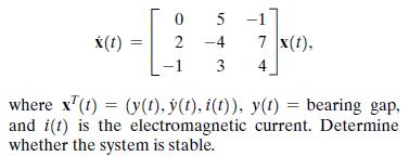
By using magnetic bearings, a rotor is supported contactless. The technique of contactless support for rotors becomes more important in light and heavy industrial applications [14]. The matrix differential equation for a magnetic bearing system is 0 x(t) 2 -4 5 7 x(t), 3 4 where x(t)=(y(t), y(t),
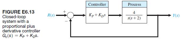
E6.13 Consider the feedback system in Figure E6.13.Determine the range of KP and KD for stability of the closed-loop system. FIGURE E6.13 Closed-loop system with a proportional plus derivative controller Gc(s) =KpKps. Controller Process 4 R(s) Kp+Kps Y(s) s(s+2)
E6.12 A system has the second-order characteristic equation s2 + as + b = 0, where a and b are constant parameters. Determine the necessary and sufficient conditions for the system to be stable. Is it possible to determine stability of a second-order system just by inspecting the coefficients of
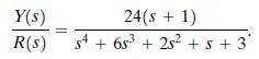
E6.11 A system with a transfer function Y(s)>R(s) isDetermine the steady-state error to a unit step input.Is the system stable? Y(s) 24(s + 1) R(s) s4+683 +252 + s + 3
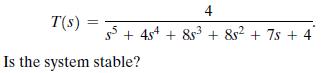
E6.10 Consider a feedback system with closed-loop transfer function 4 T(s) 5+44 +853 +852 + 7s+4 Is the system stable?
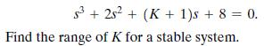
E6.9 A system has a characteristic equation 3+252 + (K+ 1)s + 8 = 0. Find the range of K for a stable system.
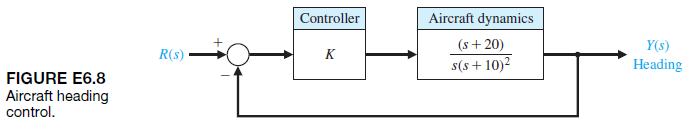
E6.8 Designers have developed small, fast, vertical- takeoff fighter aircraft that are invisible to radar (stealth aircraft). This aircraft concept uses quickly turning jet nozzles to steer the airplane [16]. The control system for the heading or direction control is shown in Figure E6.8. Determine
E6.7 For the feedback system of Exercise E6.5, find the value of K when two roots lie on the imaginary axis.Determine the value of the three roots.
E6.6 A negative feedback system has a loop transfer function(a) Find the value of the gain when the z of the closedloop roots is equal to 0.5. (b) Find the value of K when two roots lie on the imaginary axis. Determine the value of the three roots. K(s + 5) = L(s) Ge(s)G(s): = s(s - 2)
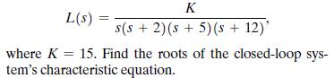
E6.5 A unity feedback system has a loop transfer function K L(s) s(s2)(s+5)(s + 12)' where K 15. Find the roots of the closed-loop sys- tem's characteristic equation.
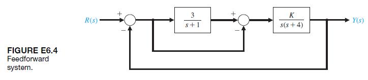
E6.4 A control system has the structure shown in Figure E6.4. Determine the gain at which the system will become unstable. FIGURE E6.4 Feedforward system. + 3 R(s) s+1 + K Y(s) s(s+4)
E6.3 A system has the characteristic equation s4 + 10s3 +32s2 + 37s + 20 = 0. Using the Routh-Hurwitz criterion, determine if the system is stable.
A system has a characteristic equation s3 + 10s2 +2s + 30 = 0. Using the Routh–Hurwitz criterion, show that the system is unstable.
A system has a characteristic equation s3 + 5K s2 +12 + K2s + 15 = 0. Determine the range of K for a stable system.
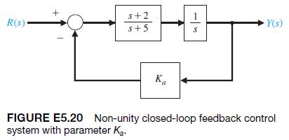
E5.20 Consider the closed-loop system in Figure E5.20, where(a) Determine the closed-loop transfer function T1s2 = Y1s2>R1s2.(b) Determine the steady-state error of the closedloop system response to a unit ramp input.(c) Select a value for Ka so that the steady-state error of the system response
E5.19 A second-order system has the closed-loop transfer function(a) Estimate the percent overshoot P.O., the time to peak Tp, and the settling time Ts of the unit step response.(b) Obtain the system response to a unit step and verify the results in part (a). 2 Y(s) 20 T(s) = R(s) s + 25ws + w
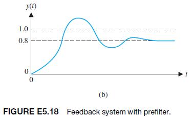
E5.18 A system is shown in Figure E5.18(a). The response to a unit step, when K = 1, is shown in Figure E5.18(b). Determine the value of K so that the steadystate error is equal to zero. 1.0 0.8 y(t) 0 0 (b) FIGURE E5.18 Feedback system with prefilter.
E5.17 A closed-loop control system transfer function T1s2 has two dominant complex conjugate poles. Sketch the region in the left-hand s-plane where the complex poles should be located to meet the given specifications. (a) 0.6 (b) 0.5 (c) 0.5, 5 wn 0.8, 0.707, n 10 wn 10 wn 10 (d) 0.707, 5 n
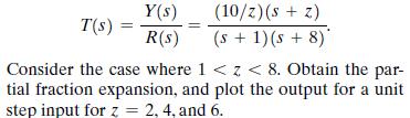
E5.16 A second-order system is Y(s) (10/z) (s + z) T(s) = R(s) (s + 1)(s+8) Consider the case where 1 < < 8. Obtain the par- tial fraction expansion, and plot the output for a unit step input for z = 2, 4, and 6.
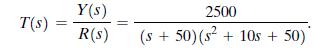
E5.15 A closed-loop control system has a transfer function T1s2 as follows:Plot y1t2 for a unit step input when (a) the actual T1s2 is used, and (b) using the dominant complex poles.Compare the results. Y(s) 2500 T(s) = R(s) (s+50) (s + 10s + 50)
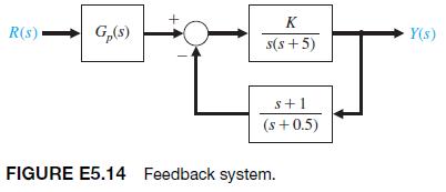
E5.14 A feedback system is shown in Figure E5.14.(a) Determine the steady-state error for a unit step when K = 0.6 and Gp1s2 = 1.(b) Select an appropriate value for Gp1s2 so that the steady-state error is equal to zero for the unit step input. K R(s) G(s) Y(s) s(s+5) s+1 (s+0.5) FIGURE E5.14
E5.13 For the system with unity feedback shown in Figure E5.11, determine the steady-state error for a step and a ramp input when 20 G(s) s+14s +50
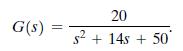
E5.12 The Ferris wheel is often featured at state fairs and carnivals. George Ferris was born in Galesburg, Illinois, in 1859; he later moved to Nevada and then graduated from Rensselaer Polytechnic Institute in 1881. By 1891, Ferris had considerable experience with iron, steel, and bridge
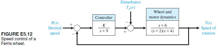
E5.11 A system with unity feedback is shown in Figure E5.11. Determine the steady-state error for a step and a ramp input when R(s) G(s) = + 10(s + 5) s(s2)(s+4) (s + 6) G(s) Y(s)
E5.10 A second-order control system has the closedloop transfer function T1s2 = Y1s2>R1s2. The system specifications for a step input follow:1. Percent overshoot P.O. … 5,.2. Settling time Ts 6 4s.3. Peak time Tp 6 1s.Show the desired region for the poles of T1s2 in order to achieve the desired
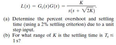
E5.9 A unity negative feedback control system has the loop transfer function L(s) Ge(s)G(s) K s(s + V2K) (a) Determine the percent overshoot and settling time (using a 2% settling criterion) due to a unit step input. (b) For what range of K is the settling time is T, = 1s?
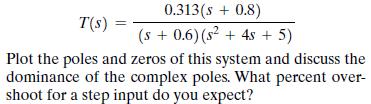
E5.8 A control system for positioning the head of a floppy disk drive has the closed-loop transfer function 0.313(s + 0.8) T(s) (s+ 0.6) (s + 4s + 5) Plot the poles and zeros of this system and discuss the dominance of the complex poles. What percent over- shoot for a step input do you expect?
E5.7 Effective control of insulin injections can result in better lives for diabetic persons. Automatically controlled insulin injection by means of a pump and a sensor that measures blood sugar can be very effective. A pump and injection system has a feedback control as shown in Figure E5.7.
E5.6 Consider the block diagram shown in Figure E5.6[16]. (a) Calculate the steady-state error for a ramp input. (b) Select a value of K that will result in zero percent overshoot to a step input. Provide rapid response.
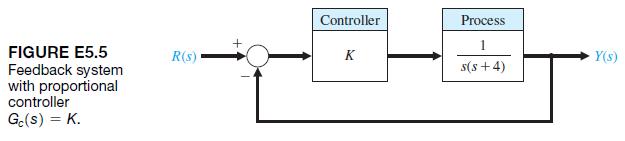
E5.5 Consider the feedback system in Figure E5.5. Find K such that the closed-loop system minimizes the ITAE performance criterion for a step input. FIGURE E5.5 Feedback system with proportional controller Gc(s) = K. Controller Process 1 R(s) K Y(s) s(s+4)
E5.4 A feedback system with negative unity feedback has a loop transfer function L(s) = Ge(s)G(s) === 2(s +8) s(s + 4) (a) Determine the closed-loop transfer function T(s) = Y(s)/R(s). (b) Find the time response, y(t), for a step input r(t) A for t> 0. (c) Determine the percent overshoot of the
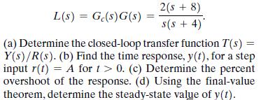
E5.3 New passenger rail systems that could profitably compete with air travel are under development. Two of these systems, the French TGV and the Japanese Shinkansen, reach speeds of 160 mph [17]. The Trans-rapid, a magnetic levitation train, is shown in Figure E5.3(a).The use of magnetic
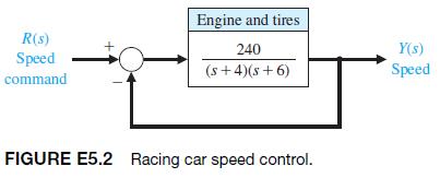
E5.2 The engine, body, and tires of a racing vehicle affect the acceleration and speed attainable [9]. The speed control of the car is represented by the model shown in Figure E5.2. (a) Calculate the steady-state error of the car to a step command in speed. (b) Calculate overshoot of the speed to a
E5.1 A motor control system for a computer disk drive must reduce the effect of disturbances and parameter variations, as well as reduce the steady-state error.We want to have no steady-state error for the headpositioning control system. (a) What type number is required? (How many integrations?)
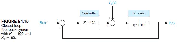
E4.15 Reconsider the unity feedback system discussed in E4.14. This time select K = 120 and K1 = 10. The closed-loop system is depicted in Figure E4.15. FIGURE E4.15 Closed-loop feedback system with K 100 and K = 50. R(s) ++ Controller K=120 Ta(s) Process 1 Y(s) + s(s+10)
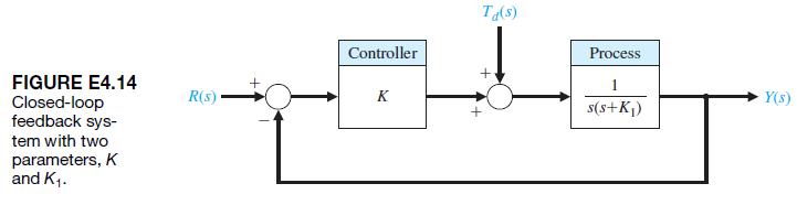
E4.14 Consider the unity feedback system shown in Figure E4.14. The system has two parameters, the controller gain K and the constant K1 in the process.(a) Calculate the sensitivity of the closed-loop transfer function to changes in K1.(b) How would you select a value for K to minimize the effects
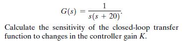
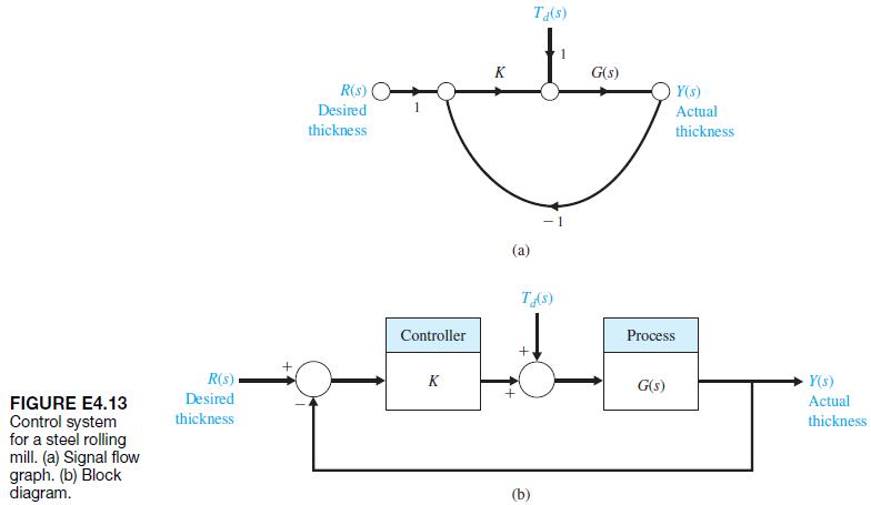
E4.13 A closed-loop system is used in a high-speed steel rolling mill to control the accuracy of the steel strip thickness. The transfer function for the process shown in Figure E4.13 can be represented as 1 G(s) == s(s +20) Calculate the sensitivity of the closed-loop transfer function to changes
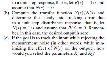
E4.12 In Figure E4.12, consider the closed-loop system with measurement noise N1s2, where G(s) = 100 s+100' Ge(s) = K, and H(s): = K 5+5 In the following analysis, the tracking error is defined to be E(s) = R(s) - Y(s): (a) Compute the transfer function T(s)= Y(s)/R(s) and determine the
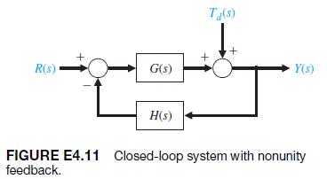
E4.11 Consider the closed-loop system in Figure E4.11, where K 14 G(s) and H(s) S+ 10 + 5s +6
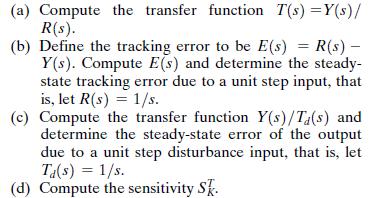
E4.10 Consider the feedback control system shown in Fig ure E4.10. (a) Determine the steady-state error for a step input in terms of the gain, K. (b) Determine the overshoot for the step response for 40 … K … 400.(c) Plot the overshoot and the steady-state error versus K. FIGURE E4.10 Feedback
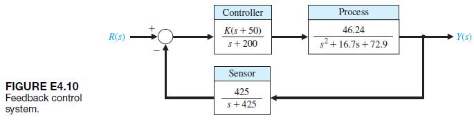
E4.9 Submersibles with clear plastic hulls have the potential to revolutionize underwater leisure. One small submersible vehicle has a depth-control system as illustrated in Figure E4.9.(a) Determine the closed-loop transfer function T1s2 = Y1s2>R1s2.(b) Determine the sensitivity SK1 T and SK T
E4.8 Four-wheel drive automobiles are popular in regions where winter road conditions are often slippery due to snow and ice. A four-wheel drive vehicle with antilock brakes uses a sensor to keep each wheel rotating to maintain traction. One system is shown in Figure E4.8. Find the closed-loop
E4.7 Most people have experienced an out-of-focus slide projector. A projector with an automatic focus adjusts for variations in slide position and temperature disturbances [11]. Draw the block diagram of an autofocus system and describe how the system works.An unfocused slide projection is a
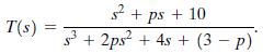
E4.6 A feedback system has the closed-loop transfer function given byCompute the sensitivity of the closed-loop transfer function to changes in the parameter p, where p 7 0.Compute the steady-state error to a unit step input as a function of the parameter p. s+ps + 10 T(s) == s3+2ps+4s+(3-p)
E4.5 A unity feedback system has the loop transfer functionDetermine the relationship between the steady-state error to a ramp input and the gain K and system parameterb. For what values of K and b can we guarantee that the magnitude of the steady-state error to a ramp input is less than 0.1? 10K
Showing 400 - 500
of 1037
1
2
3
4
5
6
7
8
9
10
11
Step by Step Answers