New Semester
Started
Get
50% OFF
Study Help!
--h --m --s
Claim Now
Question Answers
Textbooks
Find textbooks, questions and answers
Oops, something went wrong!
Change your search query and then try again
S
Books
FREE
Study Help
Expert Questions
Accounting
General Management
Mathematics
Finance
Organizational Behaviour
Law
Physics
Operating System
Management Leadership
Sociology
Programming
Marketing
Database
Computer Network
Economics
Textbooks Solutions
Accounting
Managerial Accounting
Management Leadership
Cost Accounting
Statistics
Business Law
Corporate Finance
Finance
Economics
Auditing
Tutors
Online Tutors
Find a Tutor
Hire a Tutor
Become a Tutor
AI Tutor
AI Study Planner
NEW
Sell Books
Search
Search
Sign In
Register
study help
computer science
modern database management 13th edition
Modern Control Systems 13th Global Edition Robert Bishop Richard Dorf - Solutions
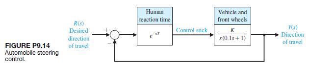
P9.14 Electronics and computers are being used to control automobiles. Figure P9.14 is an example of an automobile control system, the steering control for a research automobile. The control stick is used for steering. A typical driver has a reaction time of T = 0.2 s.(a) Using the Nichols chart,
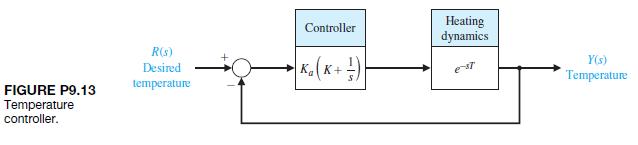
P9.13 A controller is used to regulate the temperature of a mold for plastic part fabrication, as shown in Figure P9.13. The value of the delay time is estimated as 1.2 s.(a) Using the Nyquist criterion, determine the stability of the system for Ka = K = 1. (b) Determine a suitable value for Ka for
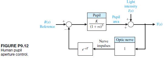
P9.12 A simplified model of the control system for regulating the pupillary aperture in the human eye is shown in Figure P9.12 [20]. The gain K represents the pupillary gain, and t is the pupil time constant, which is 0.4 s. The time delay T is equal to 0.5 s. The pupillary gain is K = 1.9.(a)
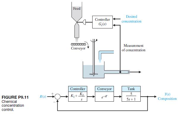
P9.11 A control system for a chemical concentration control system is shown in Figure P9.11. The system receives a granular feed of varying composition, and we want to maintain a constant composition of the output mixture by adjusting the feed-flow valve.The transport of the feed along the conveyor
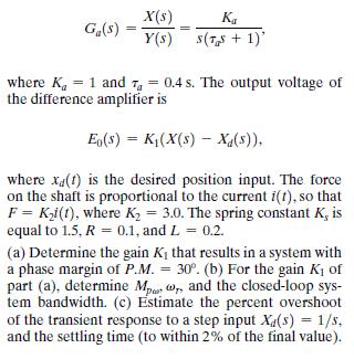
P9.10 Machine tools are often automatically controlled as shown in Figure P9.10. These automatic systems are often called numerical machine controls [9]. On each axis, the desired position of the machine tool is compared with the actual position and is used to actuate a solenoid coil and the shaft
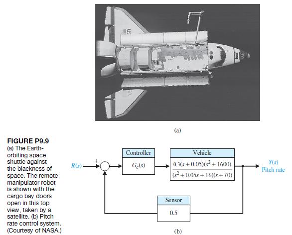
P9.9 The space shuttle, shown in Figure P9.9(a), carried large payloads into space and returned them to Earth for reuse [19]. The shuttle used elevons at the trailing edge of the wing and a brake on the tail to control the flight during entry. The block diagram of a pitch rate control system is
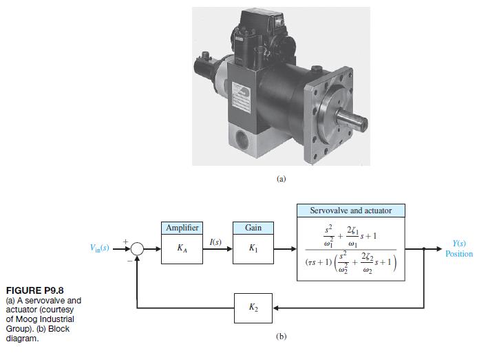
P9.8 Electrohydraulic servomechanisms are used in control systems requiring a rapid response for a large mass. An electrohydraulic servomechanism can provide an output of 100 kW or greater [17]. A photo of a servovalve and actuator is shown in Figure P9.8(a).The output sensor yields a measurement
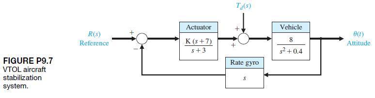
P9.7 A vertical takeoff (VTOL) aircraft is an inherently unstable vehicle and requires an automatic stabilization system. An attitude stabilization system for the K-16B U.S. Army VTOL aircraft has been designed and is shown in block diagram form in Figure P9.7 [16].(a) Obtain the Bode plot of the
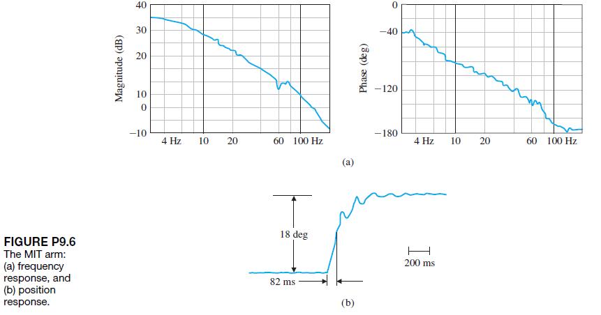
P9.6 A direct-drive arm is an innovative mechanical arm in which no reducers are used between motors and their loads. Because the motor rotors are directly coupled to the loads, the drive systems have no backlash, small friction, and high mechanical stiffness, which are all important features for
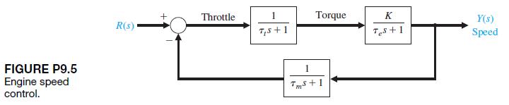
P9.5 A speed control for a gasoline engine is shown in Figure P9.5. Because of the restriction at the carburetor intake and the capacitance of the reduction manifold, the lag tt occurs and is equal to 1 second.The engine time constant te is equal to J>b = 3 s.The speed measurement time constant
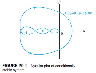
P9.4 The Nyquist plot of a conditionally stable system is shown in Figure P9.4 for a specific gain K. (a) Determine whether the system is stable, and find the number of roots (if any) in the right-hand s-plane. The system has no poles of Gc1s2G1s2 in the right half-plane.(b) Determine whether the
P9.3 (a) Find a suitable contour s in the s-plane that can be used to determine whether all roots of the characteristic equation have damping ratios greater than z1.(b) Find a suitable contour s in the s-plane that can be used to determine whether all the roots of the characteristic equation have
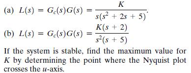
P9.2 Sketch the Nyquist plots of the following loop transfer functions L11s2 = Gc11s2G11s2, and determine whether the system is stable by applying the Nyquist criterion: K (a) L(s)G(s)G(s) = s(s + 2s + 5) K(s + 2) (b) L(s)G(s)G(s) : = s(s + 5) If the system is stable, find the maximum value for K
P9.1 For the Nyquist plots of Problem P8.1, use the Nyquist criterion to ascertain the stability of the various systems. In each case, specify the values of N, P, and Z.
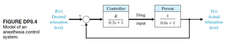
!!~!!~!!Anesthesia can be administered automatically by a control system. To ensure adequate operating conditions for the surgeon, muscle relaxant drugs, which block involuntary muscle movements, are administered.A conventional method used by anesthesiologists for muscle relaxant administration is
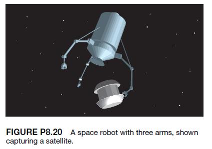
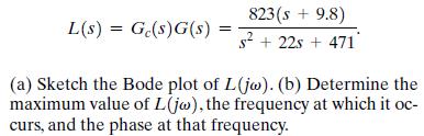
P8.20 For the successful development of space projects, robotics and automation will be a key technology.Autonomous and dexterous space robots can reduce the workload of astronauts and increase operational efficiency in many missions. Figure P8.20 shows a concept called a free-flying robot [9, 13].
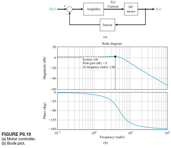
A DC motor controller used extensively in automobiles is shown in Figure P8.19(a). The measured plot of1s2>I1s2 is shown in Figure P8.19(b). Determine the transfer function of 1s2>I1s2. FIGURE P8.19 (a) Motor controller. (b) Bode plot. Phase (deg) Magnitude (dB) I(s) Current DC Ad(s)
Remote operation plays an important role in hostile environments. Research engineers have been trying to improve teleoperations by feeding back rich sensory information acquired by the robot to the operator with a sensation of presence. This concept is called tele-existence or telepresence [9].The
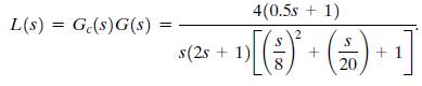
The experimental Oblique Wing Aircraft (OWA)has a wing that pivots, as shown in Figure P8.17. The wing is in the normal unskewed position for low speeds and can move to a skewed position for improved supersonic flight [11]. The aircraft control system loop transfer function is(a) Sketch the Bode
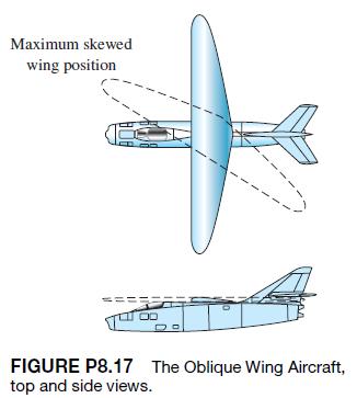
A space shuttle was used to repair satellites.Figure P8.16 illustrates how a crew member, with her feet strapped to the platform on the end of the shuttle’s robotic arm, used her arms to stop the satellite’s spin. The control system of the robotic arm has a closed-loop transfer function FIGURE
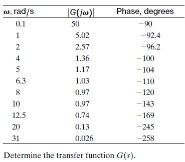
To determine the transfer function of a process G1s2, the frequency response may be measured using a sinusoidal input. One system yields the data in the following table: w, rad/s 0.1 |G(jw) Phase, degrees 50 -90 124 5.02 -92.4 2.57 -96.2 1.36 -100 5 1.17 -104 6.3 1.03 -110 8 0.97 -120 10 0.97 -143
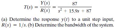
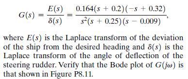
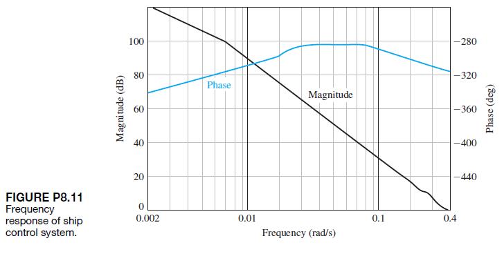
Automatic steering of a ship is a particularly useful application of feedback control theory [20]. In the case of heavily traveled seas, it is important to maintain the motion of the ship along an accurate track. An automatic system is more likely to maintain a smaller error from the desired
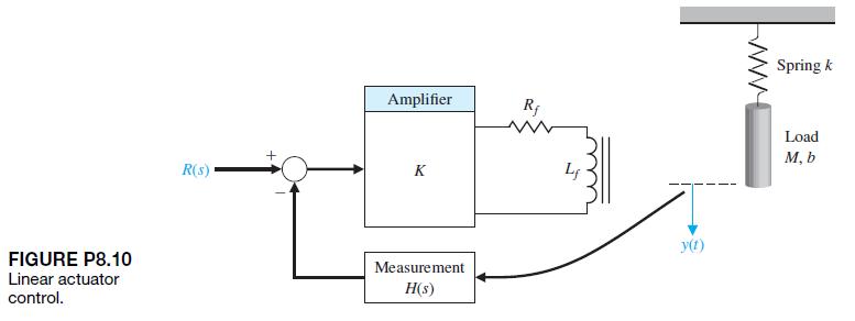
A linear actuator is used in the system shown in Figure P8.10 to position a mass M. The actual position of the mass is measured by a slide wire resistor, and thus H1s2 = 1.0. The amplifier gain is selected so that the steady-state error of the system is less than 1% of the magnitude of the position
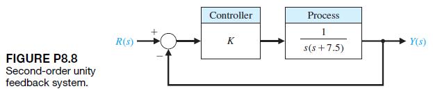
A feedback control system is shown in Figure P8.8. The specification for the closed-loop system requires that the percent overshoot to a step input be P.O. … 10,.(a) Determine the corresponding specification Mpv in the frequency domain for the closed-loop transfer function.(b) Determine the
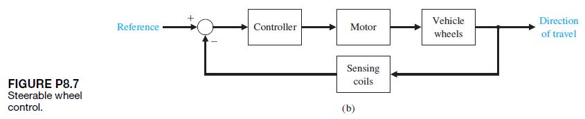
P8.7 Driverless vehicles can be used in warehouses, airports, and many other applications. These vehicles follow a wire embedded in the floor and adjust the steerable front wheels in order to maintain proper direction, as shown in Figure P8.7(a) [10].The sensing coils, mounted on the front wheel
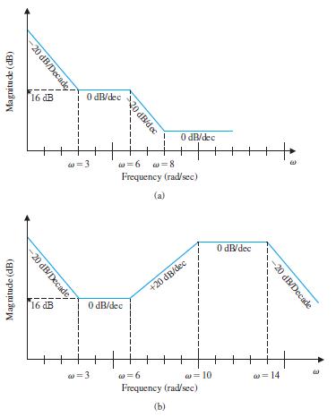
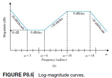
The asymptotic log-magnitude curves for two loop transfer functions are given in Figure P8.6. Sketch the corresponding asymptotic phase shift curves for each system. Estimate the transfer function for each system. Assume that the systems have minimum phase transfer functions. Magnitude (dB) -20
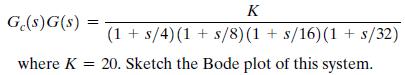
P8.5 The global robot industry is growing rapidly [8]. A typical industrial robot has multiple degrees of freedom.A unity feedback position control system for a force-sensing joint has a loop transfer function Ge(s)G(s) = K (1s/4)(1s/8)(1 + s/16)(1 + s/32) where K = 20. Sketch the Bode plot of this
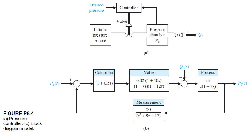
A control system for controlling the pressure in a closed chamber is shown in Figure P8.4. Sketch the Bode plot of the loop transfer function. FIGURE P8.4 (a) Pressure controller. (b) Block diagram model. Desired pressure Controller Valve Infinite Pressure pressure source chamber Po Qo e(s)
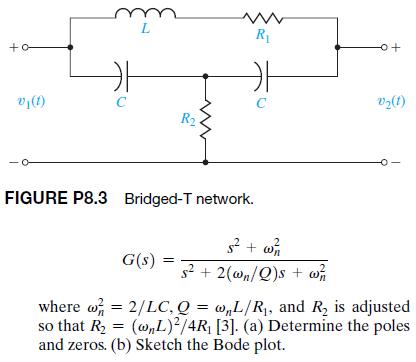
P8.3 A rejection network is the bridged-T network shown in Figure P8.3. The transfer function of this network is L +o www R -o+ v(1) C C V(1) R2 FIGURE P8.3 Bridged-T network. G(s) 5 + w s2+2(wn/Q)s + w where w = 2/LC, Q = w,L/R, and R2 is adjusted so that R = (w,L)2/4R [3]. (a) Determine the poles
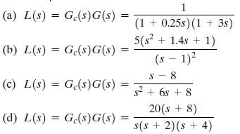
Sketch the Bode plot representation of the frequency response for the transfer functions given inProblem P8.1.Sketch the polar plot for the following loop transfer functions: (a) L(s)G(s)G(s) (b) L(s) = Ge(s)G(s) = (c) L(s) = Ge(s)G(s) (d) L(s) = Ge(s)G(s) = 1 (1+0.25s) (1 + 3s) 5(s+1.4s+1) S (s -
Sketch the polar plot for the following loop transfer functions: (a) L(s)G(s)G(s) (b) L(s) = Ge(s)G(s) = (c) L(s) = Ge(s)G(s) (d) L(s) = Ge(s)G(s) = 1 (1+0.25s) (1 + 3s) 5(s+1.4s+1) S (s - 1) - 8 s+65 +8 20(s+8) s(s + 2) (s + 4)
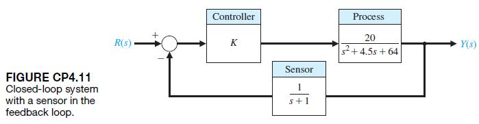
Consider the nonunity feedback system is depicted in Figure CP4.11.(a) Determine the closed-loop transfer function T1s2 = Y1s2>R1s2.(b) For K = 10, 12, and 15, plot the unit step responses. Determine the steady-state errors and the settling times from the plots.For parts (a) and (b), develop an
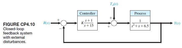
Consider the closed-loop system is depicted in Figure CP4.10. The controller gain K can be modified to meet the design specifications.(a) Determine the closed-loop transfer function T1s2 = Y1s2>R1s2.(b) Plot the response of the closed-loop system for K = 5, 10, and 50.(c) When the controller
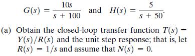
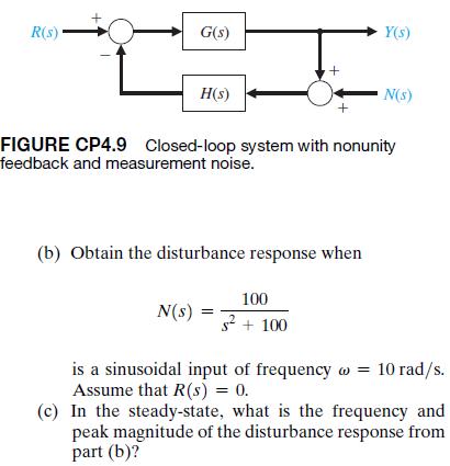
Consider the closed-loop system in Figure CP4.9, whose transfer function is G(s) == 10s s + 100 5 and H(s): = s + 50 (a) Obtain the closed-loop transfer function T(s) = Y(s)/R(s) and the unit step response; that is, let R(s) = 1/s and assume that N(s) = 0.
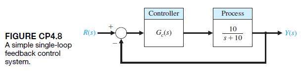
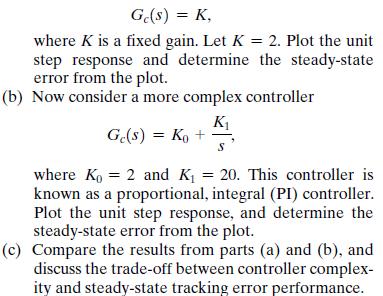
A negative feedback control system is depicted in Figure CP4.8. Suppose that our design objective is to find a controller Gc1s2 of minimal complexity such that our closed-loop system can track a unit step input with a steady-state error of zero.(a) As a first try, consider a simple proportional
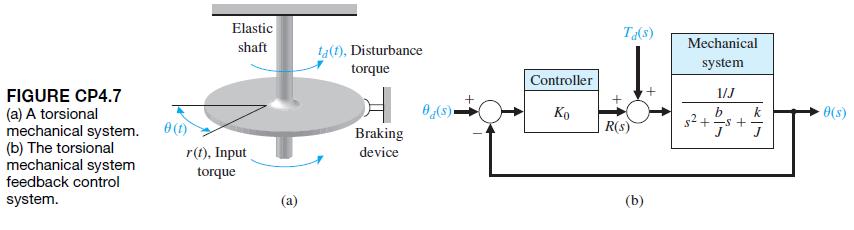
CP4.7 Consider the torsional mechanical system in Figure CP4.7(a). The torque due to the twisting of the shaft is -ku1s2; the damping torque due to the braking device is -bu1s2; the disturbance torque is Td1s2;the input torque is R1s2; and the moment of inertia of the mechanical system is J. The
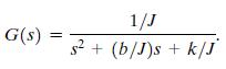
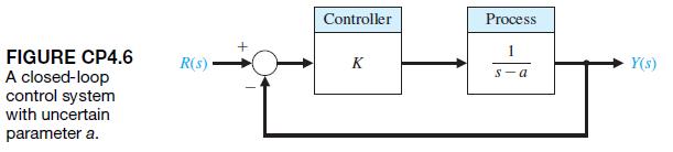
CP4.6 Consider the closed-loop control system shown in Figure CP4.6. The controller gain is K = 2. The nominal value of the plant parameter is a = 1. The nominal value is used for design purposes only, since in reality the value is not precisely known. The objective of our analysis is to
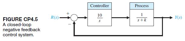
CP4.5 Consider the closed-loop control system shown in Figure CP4.5. Develop an m-file script to assist in the search for a value of k so that the percent overshoot to a unit step input is P.O. Ú 1,, but P.O. … 10,.The script should compute the closed-loop transfer function T1s2 = Y1s2>R1s2
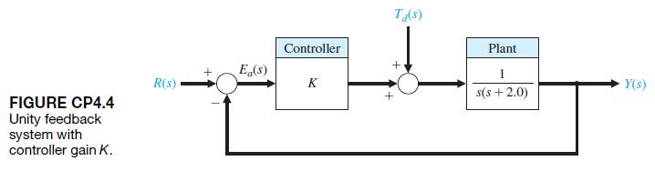
Consider the feedback system in Figure CP4.4.Suppose that the controller is K = 10.(a) Develop an m-file to compute the closed-loop transfer function T1s2 = Y1s2>R1s2 and plot the unit step response. (b) In the same m-file, compute the transfer function from the disturbance Td1s2 to the output
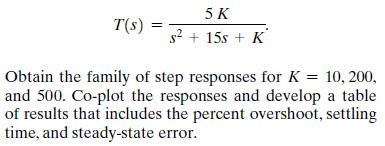
Consider the closed-loop transfer function 5K T(s) = s + 15s + K Obtain the family of step responses for K = 10,200, and 500. Co-plot the responses and develop a table of results that includes the percent overshoot, settling time, and steady-state error.
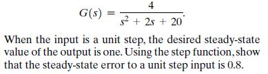
Consider the transfer function (without feedback) 4 G(s) s + 2s + 20 When the input is a unit step, the desired steady-state value of the output is one. Using the step function, show that the steady-state error to a unit step input is 0.8.
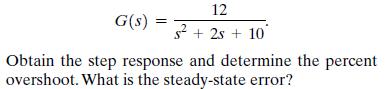
Consider a unity feedback system with 12 G(s) = s+2s+ 10 Obtain the step response and determine the percent overshoot. What is the steady-state error?
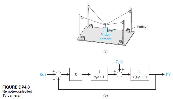
A new suspended, mobile, remote-controlled video camera system to bring three-dimensional mobility to professional football is shown in Figure DP4.8(a) [29]. The camera can be moved over the field, as well as up and down. The motor control on each pulley is represented by the system in Figure
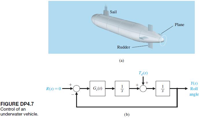
DP4.7 Interest in unmanned underwater vehicles(UUVs) has been increasing recently, with a large number of possible applications being considered.These include intelligence-gathering, mine detection, and surveillance applications. Regardless of the intended mission, a strong need exists for reliable
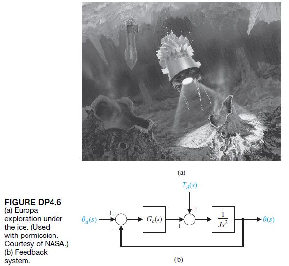
A hydrobot is under consideration for remote exploration under the ice of Europa, a moon of the giant planet Jupiter. Figure DP4.6(a) shows one artistic version of the mission. The hydrobot is a selfpropelled underwater vehicle that would analyze the chemical composition of the water in a search
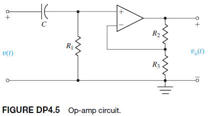
An op-amp circuit can be used to generate a short pulse. The circuit shown in Figure DP4.5 can generate the pulse v 01t2 = 5e-100t, t 7 0, when the input v1t2 is a unit step [6]. Select appropriate values for the resistors and capacitors. Assume an ideal op-amp. + v(t) HE C R R FIGURE DP4.5 Op-amp
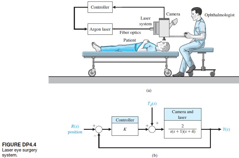
DP4.4 Lasers have been used in eye surgery for many years. They can cut tissue or aid in coagulation [17].The laser allows the ophthalmologist to apply heat to a location in the eye in a controlled manner. Many procedures use the retina as a laser target. The retina is the thin sensory tissue that
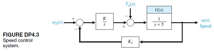
Consider the system shown in Figure DP4.3.(a) Determine the range of K1 allowable so that the steady state tracking error is ess … 1,.(b) Determine a suitable value for K1 and K so that the magnitude of the steady-state error to a wind disturbance Td1t2 = 2t mrad>s, 0 … t 6 5 s, is less than
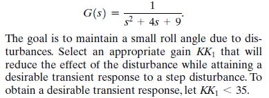
The control of the roll angle of an airplane is achieved by using the torque developed by the ailerons.A linear model of the roll control system for a small experimental aircraft is shown in Figure DP4.2, where G(s) 1 s+45 +9 The goal is to maintain a small roll angle due to dis- turbances. Select
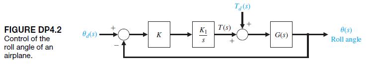
A closed-loop speed control system is subjected to a disturbance due to a load, as shown in Figure DP4.1. The desired speed is vd1t2 = 100 rad>s, and the load disturbance is a unit step input Td1s2 = 1>s.Assume that the speed has attained the no-load speed of 100 rad/s and is in steady state.
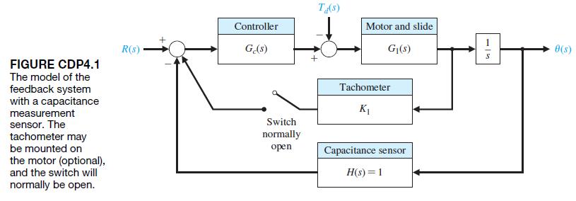
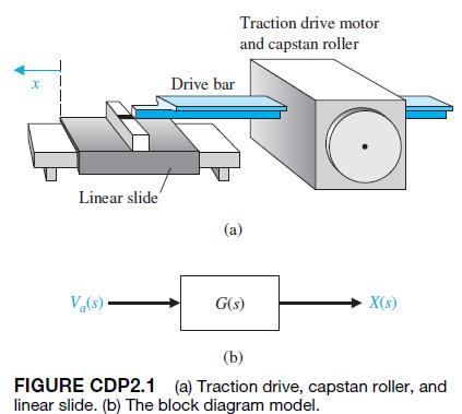
A capstan drive for a table slide is described in CDP2.1. The position of the slide x is measured with a capacitance gauge, as shown in Figure CDP4.1, which is very linear and accurate. Sketch the model of the feedback system and determine the response of the system when the controller is an
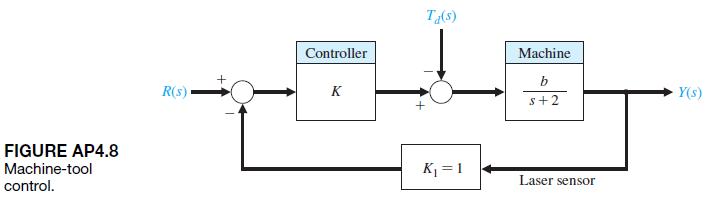
AP4.8 The block diagram of a machine-tool control system is shown in Figure AP4.8.(a) Determine the transfer function T1s2 = Y1s2>R1s2.(b) Determine the sensitivity Sb T.(c) Select K when 1 … K … 50 so that the effects of the disturbance and Sb T are minimized FIGURE AP4.8 Machine-tool
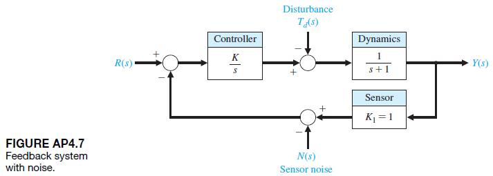
AP4.7 A feedback control system with sensor noise and a disturbance input is shown in Figure AP4.7. The goal is to reduce the effects of the noise and the disturbance.Let R1s2 = 0.(a) Determine the effect of the disturbance on Y1s2.(b) Determine the effect of the noise on Y1s2.(c) Select the best
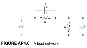
A useful circuit, called a lead network, is shown in Figure AP4.6.(a) Determine the transfer function G1s2 =V01s2>V1s2.(b) Determine the sensitivity of G1s2 with respect to the capacitance C.(c) Determine and plot the transient response V01s2 for a step input V1s2 = 1>s. C www + R + v(t)
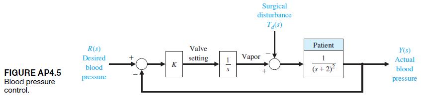
A system that controls the mean arterial pressure during anesthesia has been designed and tested [12].The level of arterial pressure is postulated to be a proxy for depth of anesthesia during surgery. A block diagram of the system is shown in Figure AP4.5, where the impact of surgery is represented
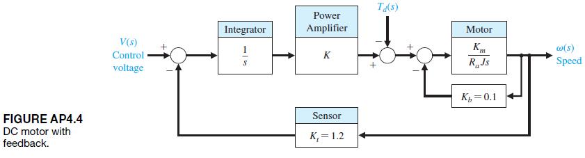
An armature-controlled DC motor with feedback is shown in Figure AP4.4. Assume that Km = 10, J = 1, and R = 1. Let the tracking error be E1s2 = V1s2 - Kt v1s2.(a) Determine the required gain, K, to restrict the steady-state error to a ramp input to 0.1 (assume that Td1s2 = 0).(b) For the gain
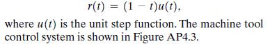
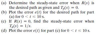
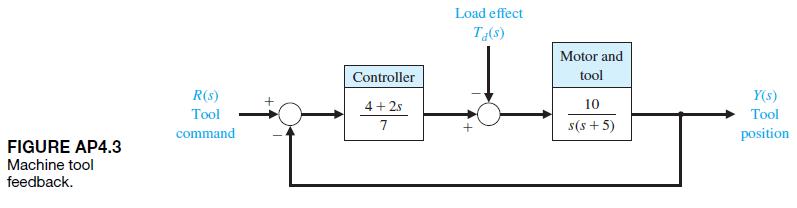
AP4.3 A machine tool is designed to follow a desired path so that r(t) = (1 t)u(t), where u(t) is the unit step function. The machine tool control system is shown in Figure AP4.3.
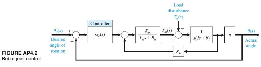
The shoulder joint of a robotic arm uses a DC motor with armature control and a set of gears on the output shaft. The model of the system is shown in Figure AP4.2 with a disturbance torque Td1s2 which represents the effect of the load. Determine the steady-state error when the desired angle input
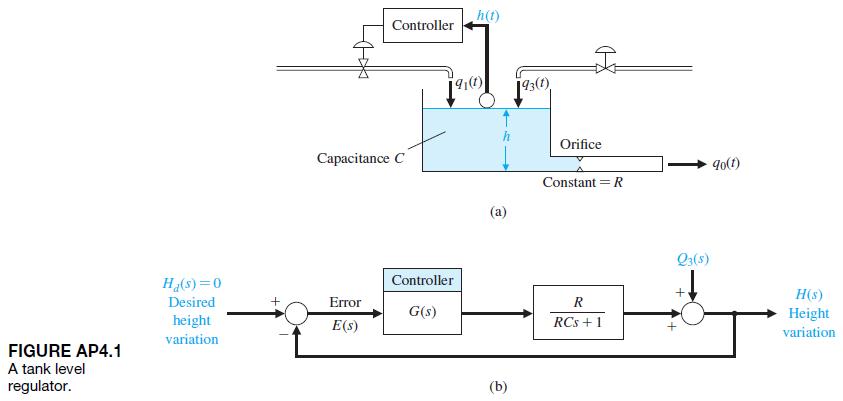
A tank level regulator control is shown in Figure AP4.1(a). It is desired to regulate the level H1s2 in response to a disturbance change Q31s2. The block diagram shows small variable changes about the equilibrium conditions so that the desired Hd1s2 = 0.Determine the equation for the error E1s2,
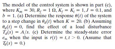
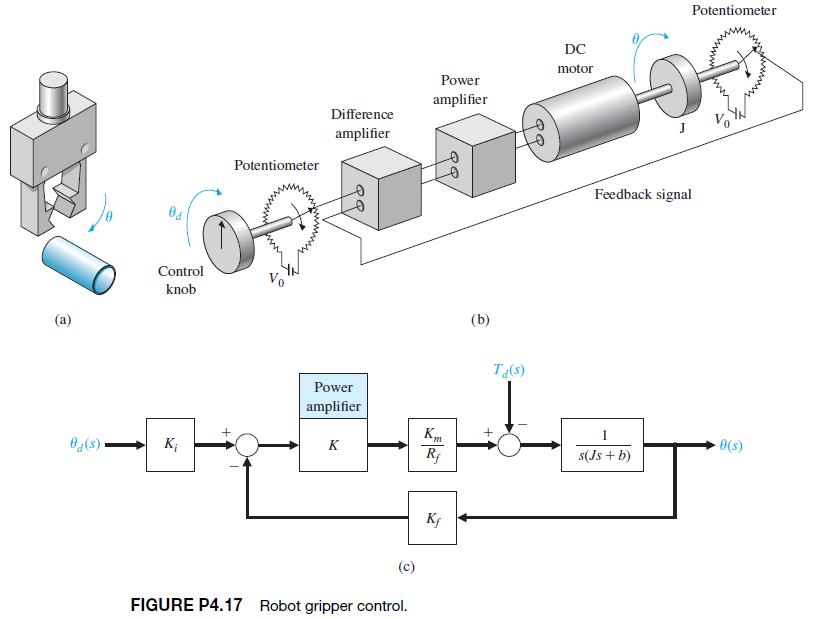
A robot gripper, shown in part (a) of Figure P4.17, is to be controlled so that it closes to an angle u by using a DC motor control system, as shown in part (b). The model of the control system is shown in part (c), where Km = 30, R = 1, K = K = 1,J = 0.1, and b = 1. (a) Determine the response (t)
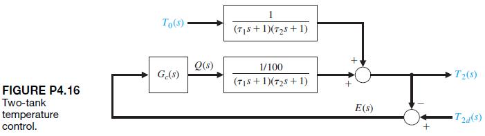
P4.16 Figure P4.16 shows the model of a two-tank system containing a heated liquid, where T01s2 is the temperature of the fluid flowing into the first tank and T21s2 is the temperature of the liquid flowing out of the second tank. The system of two tanks has a heater in the first tank with a
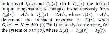
P4.15 The steering control of a modern ship may be represented by the system shown in Figure P4.15 [16, 20].(a) Find the steady-state effect of a constant wind force represented by Td1s2 = 1>s for K = 10 and K = 25.Assume that the rudder input R(s) is zero, without any disturbance, and has not
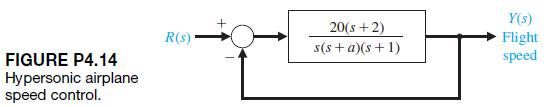
A proposed hypersonic plane would climb to 100,000 feet, fly 3800 miles per hour, and cross the Pacific in 2 hours. Control of the aircraft speed could be represented by the model in Figure P4.14. Find the sensitivity of the closed-loop transfer function T1s2 to a small change in the parameter a.
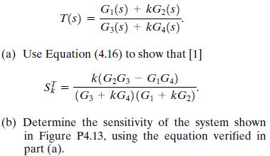
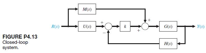
One form of a closed-loop transfer function is T(s) == G(s) + KG2(s) G3(s) + KG4(s) (a) Use Equation (4.16) to show that [1] k(GG3 - GG4) SE = (G3+kG4) (G1 + kG)* (b) Determine the sensitivity of the system shown in Figure P4.13, using the equation verified in part (a).
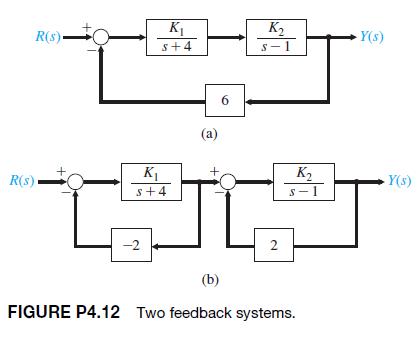
P4.12 Two feedback systems are shown in Figures P4.12(a)and (b). (a) Evaluate the closed-loop transfer functions T1 and T2 for each system. (b) Compare the sensitivities of the two systems with respect to the parameter K1 for the nominal values of K1 = K2 = 1. R(s) R(s) K S+4 K Y(s) S-1 K s+4 (a) 6
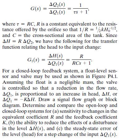
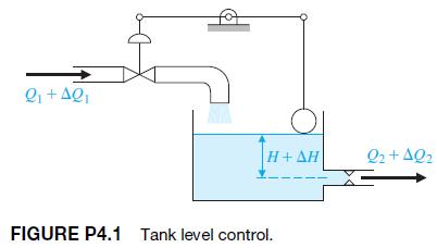
One important objective of the paper-making process is to maintain uniform consistency of the stock output as it progresses to drying and rolling. A diagram of the thick stock consistency dilution control system is shown in Figure P4.11(a). The amount of water added determines the consistency. The
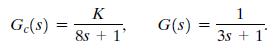
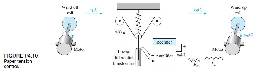
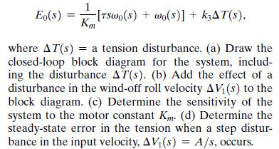
For a paper processing plant, it is important to maintain a constant tension on the continuous sheet of paper between the wind-off and wind-up rolls. The tension varies as the widths of the rolls change, and an adjustment in the take-up motor speed is necessary, as shown in Figure P4.10. If the
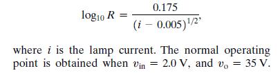
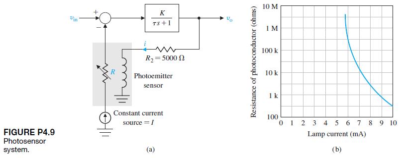
A useful unidirectional sensing device is the photoemitter sensor [15]. A light source is sensitive to the emitter current flowing and alters the resistance of the photosensor. Both the light source and the photoconductor are packaged in a single four-terminal device.This device provides a large
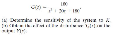
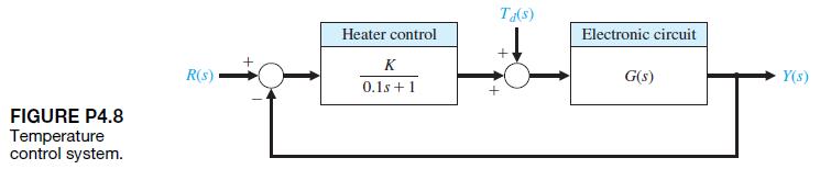
P4.8 Extreme temperature changes result in many failures of electronic circuits [1]. Temperature control feedback systems reduce the change of temperature by using a heater to overcome outdoor low temperatures.A block diagram of one system is shown in Figure P4.8. The effect of a drop in
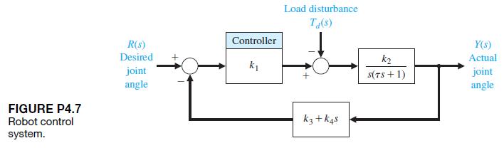
P4.7 A robot uses feedback to control the orientation of each joint axis. The load effect varies due to varying load objects and the extended position of the arm.The system will be deflected by the load carried in the gripper. Thus, the system may be represented by Figure P4.7, where the load
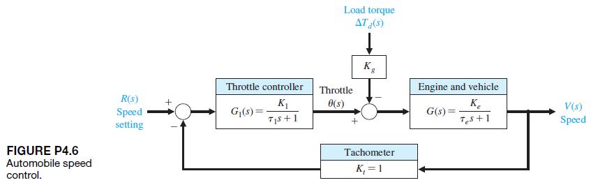
An automatic speed control system will be necessary for passenger cars traveling on the automatic highways of the future. A model of a feedback speed control system for a standard vehicle is shown in Figure P4.6. The load disturbance due to a percent grade Td1s2 is also shown. The engine gain Ke
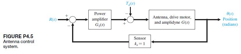
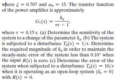
P4.5 Large microwave antennas have become increasingly important for radio astronomy and satellite tracking. A large antenna with a diameter of 60 ft, for example, is susceptible to large wind gust torques.A proposed antenna is required to have an error of less than 0.10° in a 35 mph wind.
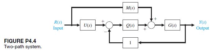
A control system has two forward paths, as shown in Figure P4.4. (a) Determine the overall transfer function T1s2 = Y1s2>R1s2. (b) Calculate the sensitivity, SG T , using Equation (4.16). (c) Does the sensitivity depend on U1s2 or M1s2? M(s) R(s) U(s) Q(s) G(s) Input Y(s) Output FIGURE P4.4
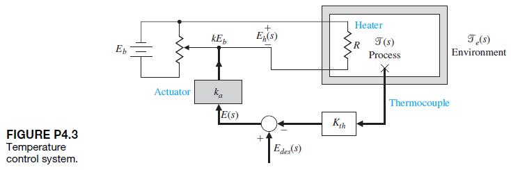
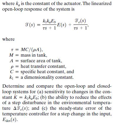
One of the most important variables that must be controlled in industrial and chemical systems is temperature.A simple representation of a thermal control system is shown in Figure P4.3 [14]. The temperature of the process is controlled by the heater with a resistance R. An approximate
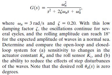
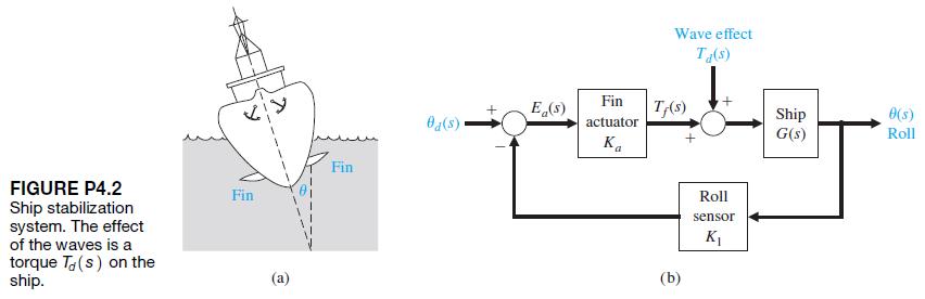
It is important to ensure passenger comfort on ships by stabilizing the ship’s oscillations due to waves [13].Most ship stabilization systems use fins or hydrofoils projecting into the water to generate a stabilization torque on the ship. A simple diagram of a ship stabilization system is shown
The open-loop transfer function of a fluid-flow system can be written as (5) 1 G(s): = 1 (5) TS + 1' where RC, R is a constant equivalent to the resis- tance offered by the orifice so that 1/R = 1/2kH, and C = the cross-sectional area of the tank. Since AH=RAQ2, we have the following for the
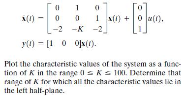
Consider the state variable model with parameter K given by 0 1 0 x(t) 0 0 1 x(t) + u(t), -2 -K -2 y(t) =[100]x(t). Plot the characteristic values of the system as a func- tion of K in the range 0 < K < 100. Determine that range of K for which all the characteristic values lie in the left
CP3.7 Consider the following system: [ ] + 1 x [ { b ] = ( -2 -3 |y(t) = [10]x(t) -2 x(t)
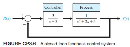
CP3.6 Consider the closed-loop control system in Figure CP3.6.(a) Determine a state variable representation of the controller.(b) Repeat part (a) for the process.(c) With the controller and process in state variable form, use the series and feedback functions to compute a closed-loop system
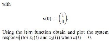
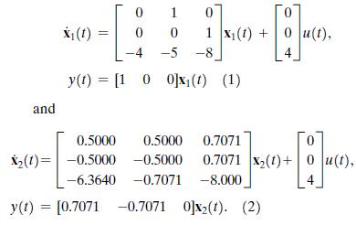
Consider the two systems(a) Using the tf function, determine the transfer function Y1s2/U1s2 for system (1).(b) Repeat part (a) for system (2).(c) Compare the results in parts (a) and (b) and comment. and 0 1 0 0 x(1) 0 0 1 x(t) + 0 u(t), -4 -5 -8 4 y(t) =[100]x(t) (1) 0.5000 0.5000 0.7071
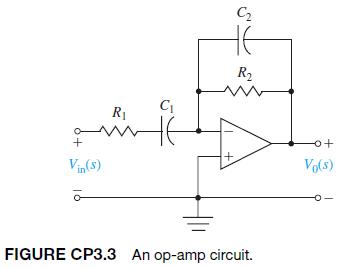
Consider the circuit shown in Figure CP3.3.Determine the transfer function V01s2>Vin1s2. Assume an ideal op-amp.(a) Determine the state variable representation when R1 = 1 k, R2 = 10 k, C1 = 0.5 mF, and C2 = 0.1 mF.(b) Using the state variable representation from part(a), plot the unit step
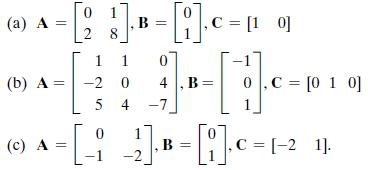
Determine a transfer function representation for the following state variable models using the tf function: 0 (a) A B 2 8 = [] c = [10] 1 0 (b) A = -2 0 4,B= 0,C=[010] 54 -7 0 (c) A C = [-2 1]. 1 -2
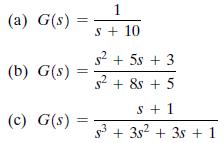
Determine a state variable representation for the following transfer functions (without feedback) using the ss function: (b) G(s) === (a) G(s) 1 S+ 10 s+5s +3 $2 s + 8s + 5 S+1 (c) G(s): = 53 +352 +35+1
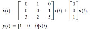
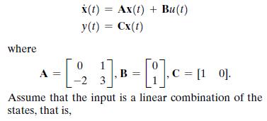
Consider the single-input, single-output system described by x(t) = Ax(t) + Bu(t) y(t) = Cx(t) where 0 A } ], B = [1]. C = [1 - 0]. Assume that the input is a linear combination of the states, that is,
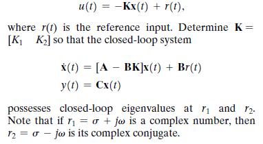
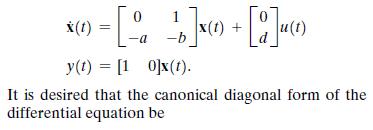
A system has the state variable matrix equation in phase variable form 1 x(t) -a -b = [a b] x + [ ] 4 (1) y(t) = [10]x(t). It is desired that the canonical diagonal form of the differential equation be
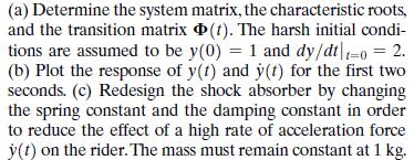
A spring-mass-damper system, as shown in Figure 3.3, is used as a shock absorber for a large high-performance motorcycle. The original parameters selected are m = 1 kg, b = 9 N s>m, and k = 20 N>m. (a) Determine the system matrix, the characteristic roots, and the transition matrix (t). The
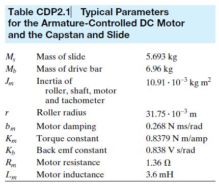
The traction drive uses the capstan drive system shown in Figure CDP2.1. Neglect the effect of the motor inductance and determine a state variable model for the system. The parameters are given in Table CDP2.1. The friction of the slide is negligible. Table CDP2.1 Typical Parameters for the
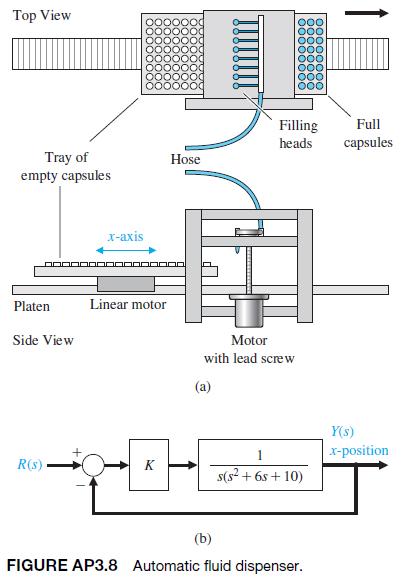
A system for dispensing radioactive fluid into capsules is shown in Figure AP3.8(a). The horizontal axis moving the tray of capsules is actuated by a linear motor. The x-axis control is shown in Figure AP3.8(b).(a) Obtain a state variable model of the closed-loop system with input r1t2 and output
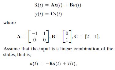
Consider the single-input, single-output system described by where A x(t) Ax(t) + Bu(t) y(t) = Cx(t) = [ ] B = [] c = 12 11. 0 Assume that the input is a linear combination of the states, that is, == u(t) = -Kx(t) + r(t),
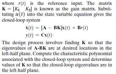
Consider a crane moving in the x direction while the mass m moves in the z direction, as shown in Figure AP3.6. The trolley motor and the hoist motor are very powerful with respect to the mass of the trolley, the hoist wire, and the load m. Consider the input control variables as the distances D(t)
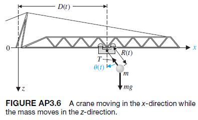
Figure AP3.5 shows a mass M suspended from another mass m by means of a light rod of length L.Obtain a state variable model using a linear model assuming a small angle for u1t2. Assume the output is the angle, u1t2. 12 www (1)x+ k|2 m www i0(1) M FIGURE AP3.5 Mass suspended from cart.
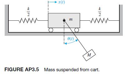
Front suspensions have become standard equipment on mountain bikes. Replacing the rigid fork that attaches the bicycle’s front tire to its frame, such suspensions absorb bump impact energy, shielding both frame and rider from jolts. Commonly used forks, however, use only one spring constant and
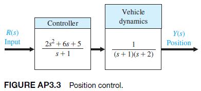
AP3.3 The control of an autonomous vehicle motion from one point to another point depends on accurate control of the position of the vehicle [16]. The control of the autonomous vehicle position Y1s2 is obtained by the system shown in Figure AP3.3. Obtain a state variable representation of the
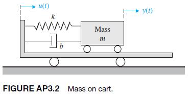
Consider the mass m mounted on a massless cart, as shown in Figure AP3.2. Determine the transfer function Y1s2/U(s), and use the transfer function to obtain a state-space representation of the system. (1)n+ wwwww Mass b m FIGURE AP3.2 Mass on cart. y(f)
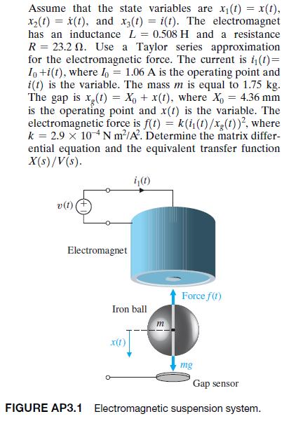
Consider the electromagnetic suspension system shown in Figure AP3.1. An electromagnet is located at the upper part of the experimental system. Using the electromagnetic forcef, we want to suspend the iron ball. Note that this simple electromagnetic suspension system is essentially unworkable.
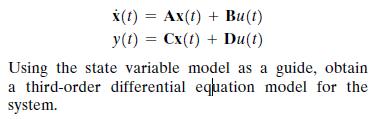
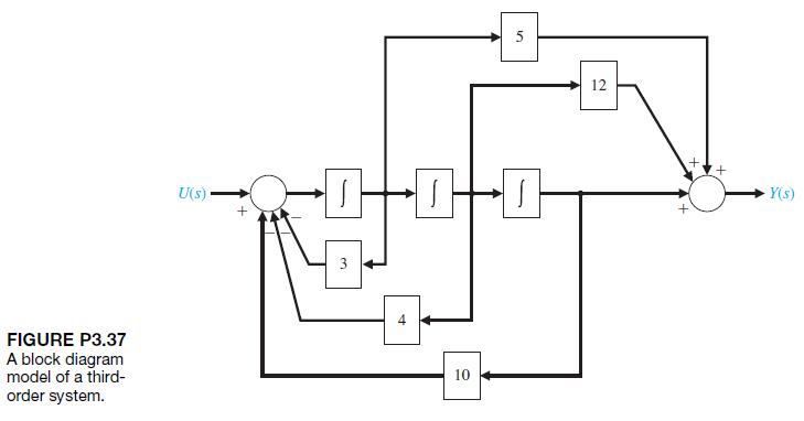
P3.37 Consider the block diagram in Figure P3.37. Using the block diagram as a guide, obtain the state variable model of the system in the form x(t) = Ax(t) + Bu(t) y(t)=Cx(t) + Du(t) Using the state variable model as a guide, obtain a third-order differential equation model for the system.
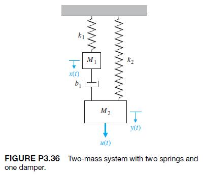
P3.36 Consider the two-mass system in Figure P3.36. Find a state variable representation of the system. Assume the output is x1t2. k x(t) M k b M2 y(1) u(t) FIGURE P3.36 Two-mass system with two springs and one damper.
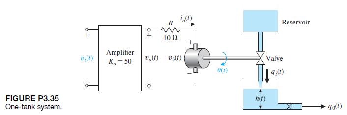
Determine a state-space representation for the system shown in Figure P3.35. The motor inductance is negligible, the motor constant is Km = 10, the back electromagnetic force constant is Kb = 0.0706, the motor friction is negligible. The motor and valve inertia is J = 0.006, and the area of the
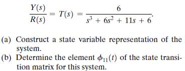
A system has the transfer function Y(s) 6 T(s) = R(s) 36s2+11s+6 (a) Construct a state variable representation of the system. (b) Determine the element 11(t) of the state transi- tion matrix for this system.
P3.33 The attitude dynamics of a rocket are represented by Y(s) G(s) U(s) = and state variable feedback is used where x(t): y(t), x2(t) = y(t), and u(t) = -x2(t) - 0.5x(1). Determine the roots of the characteristic equation of this system and the response of the system when the initial conditions
Showing 100 - 200
of 1037
1
2
3
4
5
6
7
8
9
10
11
Step by Step Answers