New Semester
Started
Get
50% OFF
Study Help!
--h --m --s
Claim Now
Question Answers
Textbooks
Find textbooks, questions and answers
Oops, something went wrong!
Change your search query and then try again
S
Books
FREE
Study Help
Expert Questions
Accounting
General Management
Mathematics
Finance
Organizational Behaviour
Law
Physics
Operating System
Management Leadership
Sociology
Programming
Marketing
Database
Computer Network
Economics
Textbooks Solutions
Accounting
Managerial Accounting
Management Leadership
Cost Accounting
Statistics
Business Law
Corporate Finance
Finance
Economics
Auditing
Tutors
Online Tutors
Find a Tutor
Hire a Tutor
Become a Tutor
AI Tutor
AI Study Planner
NEW
Sell Books
Search
Search
Sign In
Register
study help
computer science
modern database management 13th edition
Modern Control Systems 13th Global Edition Robert Bishop Richard Dorf - Solutions
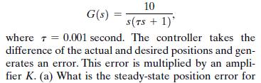
E4.4 A magnetic disk drive requires a motor to position a read/write head over tracks of data on a spinning disk, as shown in Figure E4.4. The motor and head may be represented by the transfer function 10 G(s) S(TS + 1)' where = 0.001 second. The controller takes the difference of the actual and
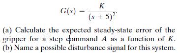
E4.3 A robotic arm and camera could be used to pick fruit, as shown in Figure E4.3(a). The camera is used to close the feedback loop to a microcomputer, which controls the arm [8, 9]. The transfer function for the process is K G(s) (s + 5)* (a) Calculate the expected steady-state error of the
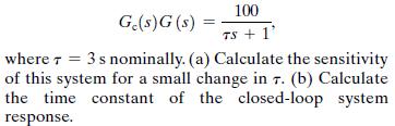
E4.2 A closed-loop system is used to track the sun to obtain maximum power from a photovoltaic array.The tracking system may be represented by a unity feedback control system and 100 Ge(s)G(s) = TS+1' where 3s nominally. (a) Calculate the sensitivity of this system for a small change in 7. (b)
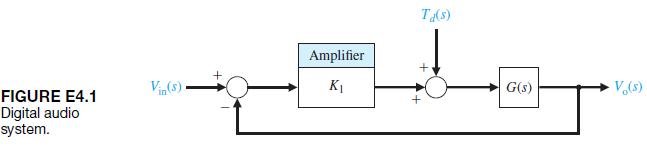
E4.1 A digital audio system is designed to minimize the effect of disturbances as shown in Figure E4.1. As an approximation, we may represent G1s2 = K2.(a) Calculate the sensitivity of the system due to K2.(b) Calculate the effect of the disturbance noise Td1s2 on Vo1s2. (c) What value would you
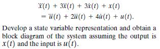
E3.23 Consider a system modeled via the third-order differential equation x(t) + 3x(t) + 3x(t) + x(t) =(t) + 2(t) + 4u (t) + u(t). Develop a state variable representation and obtain a block diagram of the system assuming the output is x(t) and the input is u(t).
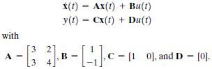
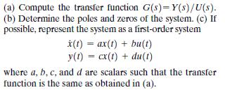
E3.22 Consider the system in state variable form with A x(t) = Ax(t) + Bu(t) y(t) =Cx(t) + Du(t) 4 [3]B= [] C = [10], and D = [0].
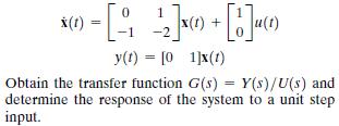
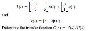
E3.21 A single-input, single-output system is described by 1 ) = [__2] x + [b]u)\ x(t) -2 y(t) = [01]x(t) u(t) Obtain the transfer function G(s) = Y(s)/U(s) and determine the response of the system to a unit step input.
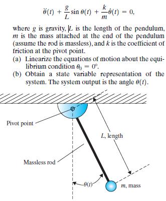
E3.20 For the simple pendulum shown in Figure E3.20, the nonlinear equations of motion are given by 8 (1) + sin (1)+(t) = 0. m where g is gravity. |L is the length of the pendulum, m is the mass attached at the end of the pendulum (assume the rod is massless), and k is the coefficient of friction
E3.19 A single-input, single-output system has the matrix equations 0 x(t) 3 and y(t) = [30]x(t). Determine the transfer function G(s) = Y(s)/U(s).
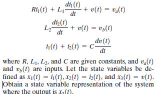
E3.18 Consider a system represented by the following differential equations: dis(t) Ri(t) +L + v(t) = va(t) dt di(t) L2 + v(t) = v(t) dt dv(t) in(t) + iz(t) = C- dt where R, L1, L2, and C are given constants, and v(t) and v(t) are inputs. Let the state variables be de- fined as xi(t) i(t), x2(t) =
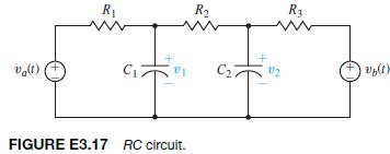
E3.17 Determine a state variable differential matrix equation for the circuit shown in Figure E3.17: R R R3 C C FIGURE E3.17 RC circuit. V(1)
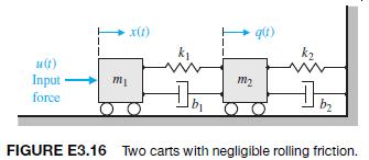
E3.16 Two carts with negligible rolling friction are connected as shown in Figure E3.16. An input force is u1t2.The output is the position of cart 2, that is, y1t2 = q1t2.Determine a state space representation of the system. x(1) q(t) u(t) Input force m m2 b FIGURE E3.16 Two carts with negligible
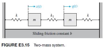
E3.15 Consider the case of the two masses connected as shown in Figure E3.15. The sliding friction of each mass has the constantb. Determine a state variable matrix differential equation. x(1) m m Sliding friction constant b FIGURE E3.15 Two-mass system. q(t)
E3.14 Develop the state-space representation of a radioactive material of mass M to which additional radioactive material is added at the rate r1t2 = Ku1t2, where K is a constant. Identify the state variables. Assume that the mass decay is proportional to the mass present.
E3.13 A system is described by the two differential equationswhere w1t2 and y1t2 are functions of time, and u1t2 is an input. (a) Select a set of state variables. (b) Write the matrix differential equation and specify the elements of the matrices. (c) Find the characteristic roots of the system in
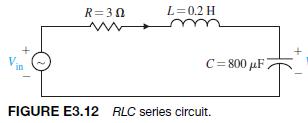
E3.12 Use a state variable model to describe the circuit of Figure E3.12. Obtain the response to an input unit step when the initial current is zero and the initial capacitor voltage is zero. R=30 L=0.2 H in C=800 F2 FIGURE E3.12 RLC series circuit.
E3.11 Determine a state variable representation for the system described by the transfer function Y(s) T(s) R(s) 4(x+3) (s + 2) (s + 6)
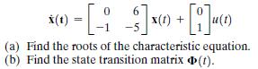
E3.10 A hovering vehicle control system is represented by two state variables, and [13] 0 6 x(t) | x(t) + [1](1) (a) Find the roots of the characteristic equation. (b) Find the state transition matrix (1).
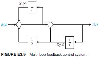
E3.9 A multi-loop block diagram is shown in Figure E3.9.The state variables are denoted by x11t2 and x21t2.(a) Determine a state variable representation of the closed-loop system where the output is denoted by y1t2 and the input is r1t2. (b) Determine the characteristic equation. R(s) X(5) -> 1
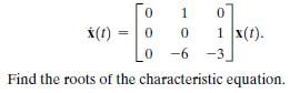
E3.8 Consider the system 0 1 0 x(t) ===== 0 0 1 x(f). 0 -6 -3. Find the roots of the characteristic equation.
E3.7 Consider the spring and mass shown in Figure 3.3 where M = 1 kg, k = 100 N>m, and b = 20 Ns>m.(a) Find the state vector differential equation. (b) Find the roots of the characteristic equation for this system.
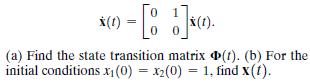
E3.6 Consider the system (a) Find the state transition matrix (t). (b) For the initial conditions x1(0) = x2(0) = 1, find x(t).
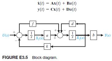
E3.5 A system is represented by a block diagram as shown in Figure E3.5. Write the state equations in the form U(s) 51- f x(t) = Ax(t) + Bu(t) ==== y(t) Cx(t) + Du(t) d 1 b Y(s) a X(5) X(s) k FIGURE E3.5 Block diagram.
E3.4 Obtain a state variable matrix for a system with a differential equation dy(t) dy(t) +4- dy(t) +6- dt3 dt dt +8y(t)=20u(t).
E3.3 A system can be represented by the state vector differential equation (1) Ax(t) + Bu(t), where 0 Find the characteristic roots of the system.
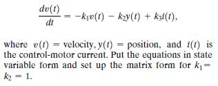
E3.2 A robot-arm drive system for one joint can be represented by the differential equation [8] dv(t) dt => -kv(t) ky(t) + ki(1), where v(t) velocity, y(t) = position, and i(t) is the control-motor current. Put the equations in state variable form and set up the matrix form for k = k = 1.
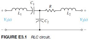
E3.1 For the circuit shown in Figure E3.1 identify a set of state variables. V(5) C R www L2 V2(3) FIGURE E3.1 RLC circuit.
E2.31 Determine the partial fraction expansion for V1s2 and compute the inverse Laplace transform. The transfer function V1s2 is given by: V(s) == 400 s+8s+400
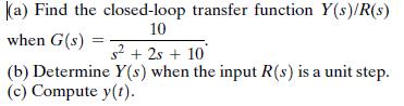
E2.30 A system is shown in Figure E2.30. (a) Find the closed-loop transfer function Y(s)/R(s) 10 when G(s) s+2s+ 10 (b) Determine Y(s) when the input R(s) is a unit step. (c) Compute y(t).
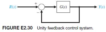
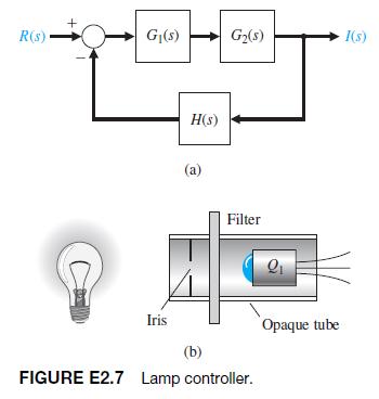
E2.29 A system is shown in Fig. E2.29(a).(a) Determine G1s2 and H1s2 of the block diagram shown in Figure E2.29(b) that are equivalent to those of the block diagram of Figure E2.29(a).(b) Determine Y1s2/R(s) for Figure E2.29(b). R(s) + 1 s+5 (a) 1 s+10 Y(s) R(s) G(s) Y(s) H(s) (b) FIGURE E2.29
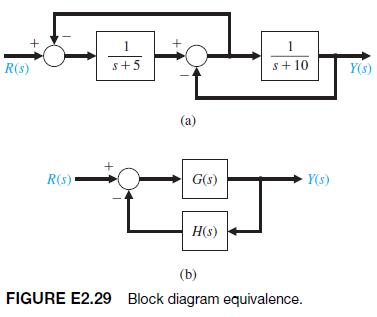
E2.28 Determine the transfer function Vo(s)>V(s) for the op-amp circuit shown in Figure E2.28 [1]. Let R1 =167 k, R2 = 240 k, R3 = 1 k, R4 = 100 k, and C = 1 mF. Assume an ideal op-amp. FIGURE E2.28 Op-amp circuit. +9 R R R3 R4 Vo +
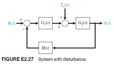
E2.27 Find the transfer function Y1s2>Td 1s2 for the system shown in Figure E2.27. R(s) G($) Ta(s) G(s) Y(s) H(s) FIGURE E2.27 System with disturbance.
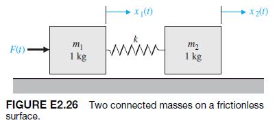
E2.26 Determine the transfer function X2 1s2>F1s2 for the system shown in Figure E2.26. Both masses slide on a frictionless surface and k = 1 N>m. x(1) m F(t)- wwwwww m2 1 kg 1 kg x2(1) FIGURE E2.26 Two connected masses on a frictionless surface.
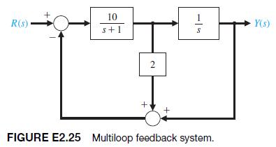
E2.25 The block diagram of a system is shown in Figure E2.25. Determine the transfer function T1s2 = Y1s2>R1s2. 10 R(s) s+1 2 + -5 FIGURE E2.25 Multiloop feedback system. Y(s)
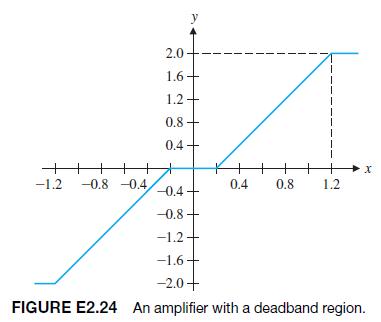
E2.24 An amplifier may have a region of deadband as shown in Figure E2.24. Use an approximation that uses a cubic equation y = ax3 in the approximately linear region. Select a and determine a linear approximation for the amplifier when the operating point is x = 0.6. 2.0 1.6- 1.2 0.8 0.4+ x -1.2
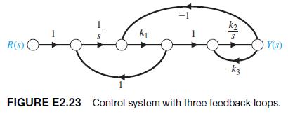
E2.23 Determine the closed-loop transfer function T1s2 =Y1s2>R1s2 for the system of Figure E2.23. R(s) ( Y(s) FIGURE E2.23 Control system with three feedback loops.
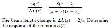
E2.22 The rotational velocity v of the satellite shown in Figure E2.22 is adjusted by changing the length of the beam L. The transfer function between v1s2 and the incremental change in beam length L1s2 is w(s) 8(s + 3) AL(s) (s + 2)(s + 3) The beam length change is AL(s) = 2/s. Determine the
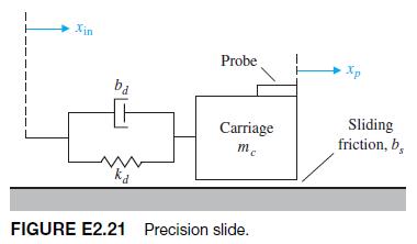
E2.21 A high-precision positioning slide is shown in Figure E2.21. Determine the transfer function Xp1s2>Xin1s2 when the drive shaft friction is bd = 0.7, the drive shaft spring constant is kd = 2, mc = 1, and the sliding friction is bs = 0.8. Xin ba Probe Xp Carriage mc FIGURE E2.21 Precision
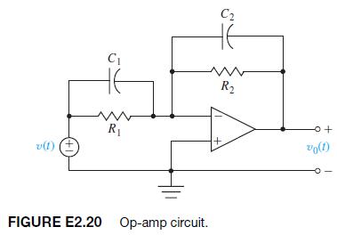
E2.20 Determine the transfer function V01s2>V1s2 of the operational amplifier circuit shown in Figure E2.20.Assume an ideal operational amplifier. Determine the transfer function when R1 = R2 =170 k, C1 =15 mF, and C2 = 25 mF. v(f) +1 C2 C www R R FIGURE E2.20 Op-amp circuit. +o vo(1)
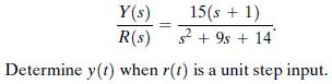
E2.19 The transfer function of a system is Y(s) 15(s + 1) R(s) 29s+ 14 Determine y(t) when r(t) is a unit step input.
E2.18 The output y and input x of a device are related by y = x + 1.9x3.(a) Find the values of the output for steady-state operation at the two operating points xo = 1.2 and xo = 2.5.(b) Obtain a linearized model for both operating points and compare them.
E2.17 A spring develops a force f represented by the relation f = kx2, where x is the displacement of the spring. Determine a linear model for the spring when xo = 12.
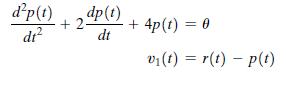
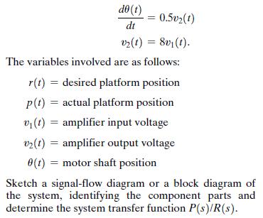
E2.16 The position control system for a spacecraft platform is governed by the following equations: dp(t) dp(t) dr +2- + 4p(t) = 0 dt v(t)=r(t)p(t)
E2.15 Obtain the differential equations for the circuit in Figure E2.15 in terms of i11t2 and i21t2. v(t) 1+) C R L i(1) 12(1) L R FIGURE E2.15 Electric circuit.
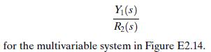
E2.14 Find the transfer function Y(s) R(s) for the multivariable system in Figure E2.14.
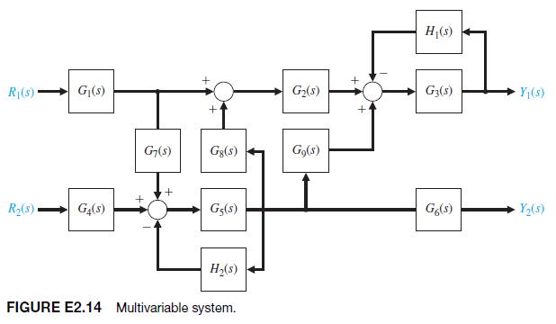
E2.13 Consider the feedback system in Figure E2.13. Compute the transfer functions Y1s2>Td1s2 and Y1s2>N1s2. Ta(s) Controller Plant + Ea(s) R(s) K Y(s) s(s+20) FIGURE E2.13 Feedback system with measurement noise, N(s), and plant disturbances, T(s). N(s)
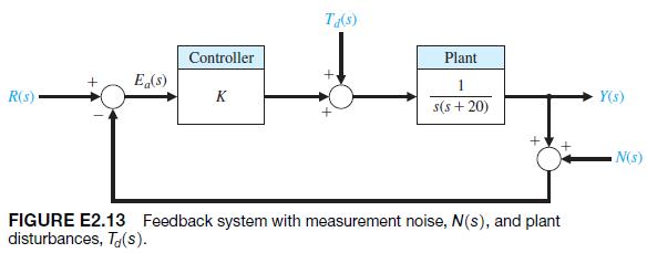
E2.12 Off-road vehicles experience many disturbance inputs as they traverse over rough roads. An active suspension system can be controlled by a sensor that looks “ahead” at the road conditions. An example of a simple suspension system that can accommodate the bumps is shown in Figure E2.12.
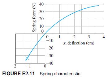
E2.11 A spring exhibits a force-versus-displacement characteristic as shown in Figure E2.11. For small deviations from the operating point xo, find the spring constant when xo is (a) -1.1; (b) 0; (c) 2.8. Spring force (N) 40 30 20 10 0 0 1 -10 -20 -30 -40 -2 -1 0 2 3 4 x, deflection (cm) FIGURE
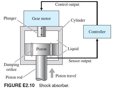
E2.10 One of the beneficial applications of an automotive control system is the active control of the suspension system. One feedback control system uses a shock absorber consisting of a cylinder filled with a compressible fluid that provides both spring and damping forces [17]. The cylinder has a
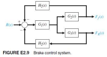
E2.9 A four-wheel antilock automobile braking system uses electronic feedback to control automatically the brake force on each wheel [15]. A block diagram model of a brake control system is shown in Figure E2.9, where Ff 1s2 and FR1s2 are the braking force of the front and rear wheels,
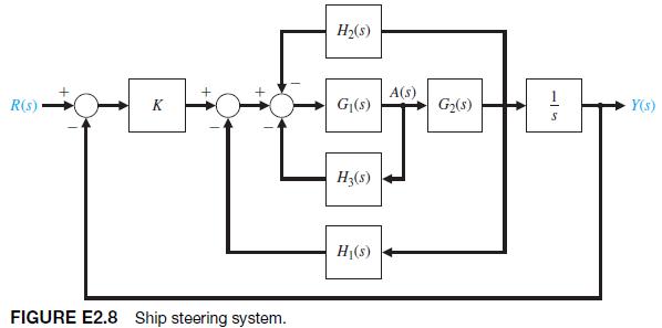
E2.8 A control engineer, N. Minorsky, designed an innovative ship steering system in the 1930s for the U.S.Navy. The system is represented by the block diagram shown in Figure E2.8, where Y1s2 is the ship’s course, R1s2 is the desired course, and A1s2 is the rudder angle [16]. Find the transfer
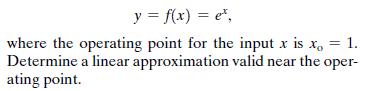
E2.7 A lamp’s intensity stays constant when monitored by an optotransistor-controlled feedback loop. When the voltage drops, the lamp’s output also drops, and optotransistor Q1 draws less current. As a result, a power transistor conducts more heavily and charges a capacitor more rapidly [24].
E2.6 A nonlinear device is represented by the function y = f(x) = ex, 1. where the operating point for the input x is xo Determine a linear approximation valid near the oper- ating point.
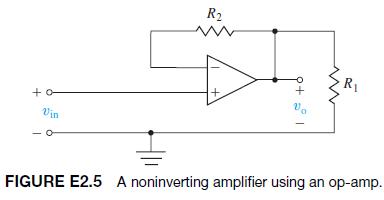
E2.5 A noninverting amplifier uses an op-amp as shown in Figure E2.5. Assume an ideal op-amp model and determine v o >v in. +o Vin R2 + v. FIGURE E2.5 A noninverting amplifier using an op-amp.
E2.4 A laser printer uses a laser beam to print copy rapidly for a computer. The laser is positioned by a control input r1t2, so that we have 4(s + 50) Y(s) == -R(s). s+30s+2001 The input r(t) represents the desired position of the laser beam. (a) If r(t) is a unit step input, find the output y(t).
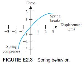
E2.3 The force versus displacement for a spring is shown in Figure E2.3 for the spring-mass-damper system of Figure 2.1. Graphically find the spring constant for the equilibrium point of y = 1.0 cm and a range of operation of + 2.0 cm. -3-2-1 2 1 Force Spring breaks + + 1 2 3. A Displacement (cm)
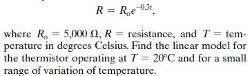
E2.2 A thermistor has a response to temperature represented by R = Roe 0.31 where R = 5,000 2, R = resistance, and T = tem- perature in degrees Celsius. Find the linear model for the thermistor operating at T = 20C and for a small range of variation of temperature.
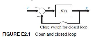
E2.1 A unity, negative feedback system has a nonlinear function y = f1e2 = e2, as shown in Figure E2.1. For an input r in the range of 0 to 4, calculate and plot the open-loop and closed-loop output versus input and show that the feedback system results in a more linear relationship. T f(e) Close
E1.14 Sketch a block diagram of a person playing a video game. Suppose that the input device is a joystick and the game is being played on a desktop computer.
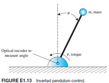
E1.13 Consider the inverted pendulum shown in Figure E1.13. Sketch the block diagram of a feedback control system. Identify the process, sensor, actuator, and controller. The objective is keep the pendulum in the upright position, that is to keep u = 0, in the presence of disturbances. Optical
E1.12 Unmanned aerial vehicles (UAVs) are being developed to operate in the air autonomously for long periods of time. By autonomous, we mean that there is no interaction with human ground controllers. Sketch a block diagram of an autonomous UAV that is tasked for crop monitoring using aerial
E1.11 Future advanced commercial aircraft will be E-enabled. This will allow the aircraft to take advantage of continuing improvements in computer power and network growth. Aircraft can continuously communicate their location, speed, and critical health parameters to ground controllers, and gather
E1.10 Describe the process of human biofeedback used to regulate factors such as pain or body temperature.Biofeedback is a technique whereby a human can, with some success, consciously regulate pulse, reaction to pain, and body temperature.
E1.9 Describe the block diagram of the control system of a skateboard with a human rider.
E1.8 Modern automated highways are being implemented around the world. Consider two highway lanes merging into a single lane. Describe a feedback control system carried on the automobile trailing the lead automobile that ensures that the vehicles merge with a prescribed gap between the two vehicles.
E1.7 Because a sailboat cannot sail directly into the wind, and traveling straight downwind is usually slow, the shortest sailing distance is rarely a straight line. Thus sailboats tack upwind—the familiar zigzag course—and jibe downwind. A tactician’s decision of when to tack and where to go
E1.6 An autofocus camera will adjust the distance of the lens from the film by using a beam of infrared or ultrasound to determine the distance to the subject[42]. Sketch a block diagram of this control system, and briefly explain its operation.
E1.5 Fly-fishing is a sport that challenges the person to cast a small feathery fly using a light rod and line.The goal is to place the fly accurately and lightly on the distant surface of the stream [59]. Describe the fly-casting process and a model of this process.
E1.4 An automobile driver uses a control system to maintain the speed of the car at a prescribed level. Sketch a block diagram to illustrate this feedback system.
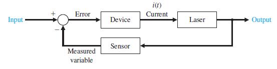
E1.3 A precise optical signal source can control the output power level to within 1% [32]. A laser is controlled by an input current to yield the power output. A microprocessor controls the input current to the laser.The microprocessor compares the desired power level with a measured signal
E1.2 Describe typical actuators that can convert the following[93]:a. Fluidic energy to mechanical energyb. Electrical energy to mechanical energyc. Mechanical deformation to electrical energyd. Chemical energy to kinetic energye. Heat to electrical energy
E1.1 Describe typical sensors that can measure each of the following [93]:a. Linear positionb. Velocity (or speed)c. Nongravitational accelerationd. Rotational position (or angle)e. Rotational velocityf. Temperature g. Pressure h. Liquid (or gas) flow rate i. Torque j. Force k. Earth’s magnetic
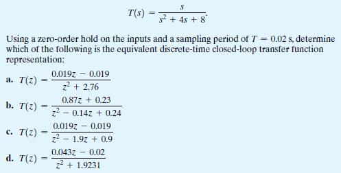
Consider a continuous-time system with the closed-loop transfer function = S T(s) =3 +45 + 8 Using a zero-order hold on the inputs and a sampling period of 7 = 0.02 s, determine which of the following is the equivalent discrete-time closed-loop transfer function representation: a. T(z) = b. T(z) ==
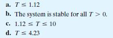
The range of the sampling period T for which the closed-loop system is stable is: a. T1.12 b. The system is stable for all T> 0. c. 1.12 T 10 d. T 4.23
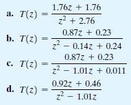
The closed-loop transfer function T1z2 of this system using a sampling period of T = 0.5 s is which of the following: 1.76z +1.76 a. T(z) z + 2.76 0.87z+0.23 b. T(z) z2 0.14z+0.24 0.87z + 0.23 c. T(z) z2 1.01z +0.011 0.922 + 0.46 d. T(z) = = z - 1.01z
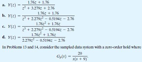
The unit step response of the closed-loop system is: a. Y(z) b. Y(z) = = c. Y(z) = d. Y(z) = 1.76z + 1.76 z + 3.279z + 2.76 1.76z + 1.76 z3 +2.279z2 0.5194z - 2.76 - 1.76z + 1.76z z3+2.279z2 0.5194z - 2.76 1.76z + 1.76z 2.279z2 -0.5194z - 2.76 In Problems 13 and 14, consider the sampled data system
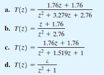
The closed-loop transfer function T1z2 of this system with sampling at T = 1 s is a. T(z) = 1.76z + 1.76 z + 3.279z +2.76 Z +1.76 b. T(z) z + 2.76 c. T(z) === 1.76z + 1.76 z + 1.519z+1 d. T(z) = 2+1
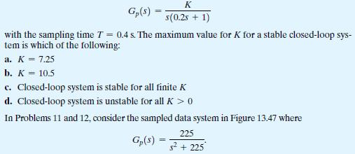
Consider the unity feedback system in Figure 13.47, where K Gp($) s(0.25 + 1) with the sampling time 7 = 0.4 s. The maximum value for K for a stable closed-loop sys- tem is which of the following: a. K = 7.25 b. K = 10.5 c. Closed-loop system is stable for all finite K d. Closed-loop system is
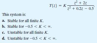
Consider a sampled-data system with the closed-loop system transfer function = T(2) K- This system is: a. Stable for all finite K. b. Stable for -0.5 < K < . c. Unstable for all finite K. d. Unstable for -0.5 < K < 0. z + 2z z + 0.22 -0.5"
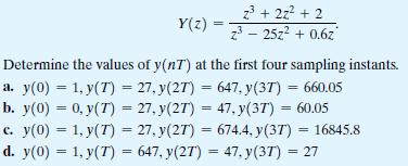
The impulse response of a system is given by z + 2z + 2 Y(z) = z - 25z + 0.6z" Determine the values of y(nT) at the first four sampling instants. 27, y(27) = 647, y(3T) = 660.05 = a. y(0) 1, y(7) b. y(0) = 0, y(T) = 27, y(27) = 47, y(37) = 60.05 c. y(0) = 1, y(T) = 27, y(27) = 674.4, y(37) =
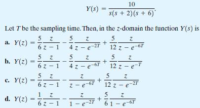
Consider the function in the s-domain 10 Y(s) === s(s + 2)(s+6)* Let T be the sampling time. Then, in the z-domain the function Y(s) is 5 Z a. Y(z) = 1 2 5 Z 5 Z 4z-e-2T + 12 z-e-67 5 Z 5 Z + 5 N + b. Y(z) = 56 6 z-1 5 Z c. Y(z) = 1 d. Y(z) = 1 - N 6z-1 4z-e-6 12z-e-T Z z-e-67 Z 12 z-e-27 5 Z +
The z-transform is a conformal mapping from the s-plane to the z-plane by the relation z = esT. True or False
A sampled system is stable if all the poles of the closed-loop transfer function lie outside the unit circle of the z-plane. True or False
Root locus methods are not applicable to digital control system design and analysis. True or False
The sampled signal is available only with limited precision. True or False
A digital control system uses digital signals and a digital computer to control a process. True or False
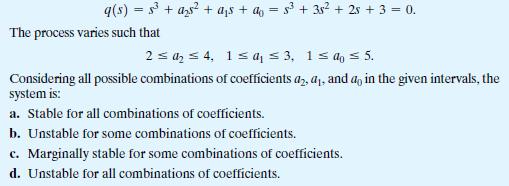
A feedback control system has the nominal characteristic equation 9(s) = 5 + a25 + as + a = s + 38 + 2 + 3 = 0. The process varies such that 2 a4, 1 a 3, 1 a 5. Considering all possible combinations of coefficients a, a, and a, in the given intervals, the system is: a. Stable for all
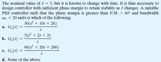
Consider the feedback control system in Figure 12.45 with 1 Gr(s) = 1 and G(s) Js
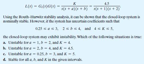
Consider a unity negative feedback system with a loop transfer function (with nominal values) L(s) = Ge(s)G(s) K s(sa)(s+b) 4.5 s(s + 1)(s + 2) Using the Routh-Hurwitz stability analysis, it can be shown that the closed-loop system is nominally stable. However, if the system has uncertain
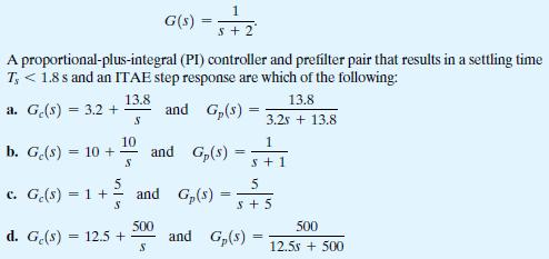
Consider the feedback control system in Figure 12.45 with plant 1 G(s)=5+2 A proportional-plus-integral (PI) controller and prefilter pair that results in a settling time T
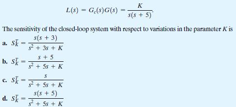
Consider the system in Figure 12.45 with Gp(s) = 1 and loop transfer function K = L(s) G(s)G(s) = s(s + 5) The sensitivity of the closed-loop system with respect to variations in the parameter K is = a. Sk = b. Sk c. Sk d. Sk = == s(s + 3) s + 35+ K S+5 s +55 + K S +5s + K s(s + 5) +5s + K
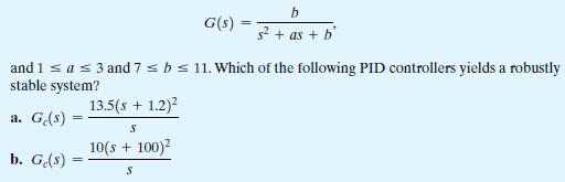
Consider the system in Figure 12.45 with Gp(s) = 1, b G(s) s + as + b and 1 a 3 and 7 b 11. Which of the following PID controllers yields a robustly stable system? a. Ge(s) = = b. G(s) = 13.5(s + 1.2) S 10(s + 100)2 S
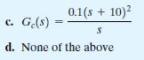
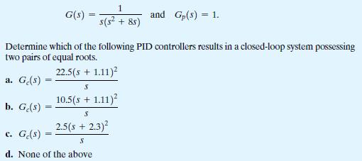
Consider the closed-loop system block-diagram in Figure 12.45, where 1 G(s) = s(s + 8s) and Gp(s) = 1. Determine which of the following PID controllers results in a closed-loop system possessing two pairs of equal roots. 22.5(s + 1.11) a. Ge(s) S 10.5(s + 1.11) b. G(s) = c. Ge(s) = S 2.5(s + 2.3) S
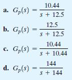
Considering the same PI controller as in Problem 7, a suitable prefilter, Gp1s2, which provides optimum ITAE response to a step input is: a. G(s) = b. G(s) 10.44 S+ 12.5 12.5 s+12.5 c. G(s) = d. G(s) 10.44 S+ 10.44 144 S+144
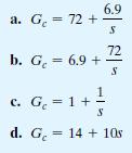
The proportional-plus-integral (PI) controller, Gc1s2, that provides optimum coefficients of the characteristic equation for ITAE(assuming vn = 12 and a step input) is which of the following: Ge a. G = 72+ b. G = 6.9 + =1 c. G = 1 + S 6.9 S 72 S d. G = 14 + 10s
Assume that the prefilter is Gp1s2 =
A closed-loop feedback system has the third-order characteristic equation q(s)=3+as+as+ao = 0, => where the nominal values of the coefficients are a = 3, a = 6, and do = 11. The uncertainty in the coefficients is such that the actual values of the coefficients can lie in the intervals 2 4, 4 a 9,
Control system designers seek small loop gain L(s) in order to minimize the sensitivity S(s) . True or False
A plant model will always be an inaccurate representation of the actual physical system. True or False
The PID controller consists of three terms in which the output is the sum of a proportional term, an integrating term, and a differentiating term, with an adjustable gain for each term. True or False
Showing 500 - 600
of 1037
1
2
3
4
5
6
7
8
9
10
11
Step by Step Answers