New Semester
Started
Get
50% OFF
Study Help!
--h --m --s
Claim Now
Question Answers
Textbooks
Find textbooks, questions and answers
Oops, something went wrong!
Change your search query and then try again
S
Books
FREE
Study Help
Expert Questions
Accounting
General Management
Mathematics
Finance
Organizational Behaviour
Law
Physics
Operating System
Management Leadership
Sociology
Programming
Marketing
Database
Computer Network
Economics
Textbooks Solutions
Accounting
Managerial Accounting
Management Leadership
Cost Accounting
Statistics
Business Law
Corporate Finance
Finance
Economics
Auditing
Tutors
Online Tutors
Find a Tutor
Hire a Tutor
Become a Tutor
AI Tutor
AI Study Planner
NEW
Sell Books
Search
Search
Sign In
Register
study help
computer science
systems analysis design
Power System Analysis And Design 6th Edition J. Duncan Glover, Thomas Overbye, Mulukutla S. Sarma - Solutions
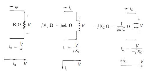
For a purely capacitive circuit, with sinusoidal-steady-state excitation, the voltage and current phasors are(a) In phase(b) Perpendicular to each other with \(V\) leading \(I\)(c) Perpendicular to each other with \(I\) leading \(V\).
With sinusoidal-steady-state excitation, the average power in a singlephase ac circuit with a purely resistive load is given by(a) \(\mathrm{I}_{\mathrm{rms}}^{2} R\)(b) \(\mathrm{V}_{\max }^{2} / R\)(c) Zero
The average power in a single-phase ac circuit with a purely inductive load, for sinusoidal-steady-state excitation, is(a) \(\mathrm{I}^{2} X_{\mathrm{L}}\)(b) \(\mathrm{V}_{\max }^{2} / X_{\mathrm{L}}\)(c) Zero \(X_{\mathrm{L}}=(\omega \mathrm{L})\) is the inductive reactance
The average power in a single-phase ac circuit with a purely capacitive load, for sinusoidal-steady-state excitation, is(a) Zero(b) \(\mathrm{V}_{\max }^{2} / X_{\mathrm{C}}\)(c) \(\mathrm{I}_{\mathrm{rms}}^{2} X_{\mathrm{C}}\) \(X_{\mathrm{C}}=1 /(\omega \mathrm{C})\) is the capacitive reactance
The average value of a double-frequency sinusoid, \(\sin 2(\omega t+\delta)\), is given by(a) 1(b) \(\delta\)(c) Zero
The power factor for an inductive circuit ( \(R\) - \(L\) load), in which the current lags the voltage, is said to be(a) Lagging(b) Leading(c) Zero
The power factor for a capacitive circuit ( \(R-C\) load), in which the current leads the voltage, is said to be(a) Lagging(b) Leading(c) One
In a single-phase ac circuit, for a general load composed of RLC elements under sinusoidal-steady-state excitation, the average reactive power is given by(a) Vrms IrmscosϕVrms Irmscosϕ(b) VrmsIrmssinϕVrmsIrmssinϕ(c) Zero ϕϕ is the power-factor angle
The instantaneous power absorbed by the load in a single-phase ac circuit, for a general RLC load under sinusoidal-steady-state excitation, is(a) Nonzero constant(b) Zero(c) Containing double-frequency components
With load convention, where the current enters the positive terminal of the circuit element, if \(\Omega\) is positive then positive reactive power is absorbed.(a) True(b) False
With generator convention, where the current leaves the positive terminal of the circuit element, if \(P\) is positive then positive real power is delivered.(a) False(b) True
Consider the load convention that is used for the RLC elements shown in Figure 2.2 of the text.A. If one says that an inductor absorbs zero real power and positive reactive power, is it(a) True(b) False B. If one says that a capacitor absorbs zero real power and negative reactive power (or
In an ac circuit, power factor improvement is achieved by(a) Connecting a resistor in parallel with the inductive load.(b) Connecting an inductor in parallel with the inductive load.(c) Connecting a capacitor in parallel with the inductive load.
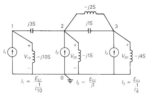
The admittance of the impedance \(-j \frac{1}{2} \Omega\) is given by(a) \(-j 2 S\)(b) \(j 2 S^{2}\)(c) \(-j 4 S\)
Consider Figure 2.9 of the text. Let the nodal equations in matrix form be given by Eq. (2.4.1) of the text.A. The element Y11Y11 is given by(a) 0(b) j13j13(c) −j7−j7B. The element Y31Y31 is given by(a) 0(b) −j5−j5(c) j1j1C. The admittance matrix is always symmetric square.(a) False(b)
The three-phase source line-to-neutral voltages are given by \(E_{a n}=10 \angle 0^{\circ}\), \(E_{b n}=10 \angle+240^{\circ}\), and \(E_{c n}=10 \angle-240^{\circ}\) volts.Is the source balanced?(a) Yes(b) No
In a balanced three-phase Y-connected system with a positive-sequence source, the line-to-line voltages are \(\sqrt{3}\) times the line-to-neutral voltages and lend by \(30^{\circ}\).(a) True(b) False
In a balanced system, the phasor sum of the line-to-line voltages and the phasor sum of the line-to-neutral voltages are always equal to zero.(a) False(b) True
Consider a three-phase Y-connected source feeding a balanced- \(\Delta\) load. The phasor sum of the line currents as well as the neutral current are always zero.(a) True(b) False
For a balanced- \(\Delta\) load supplied by a balanced positive-sequence source, the line currents into the load are \(\sqrt{3}\) times the \(\Delta\)-load currents and lag by \(30^{\circ}\).(a) True(b) False
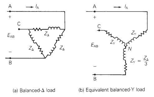
A balanced \(\Delta\)-load can be converted to an equivalent balanced- \(Y\) load by dividing the \(\Delta\)-load impedance by(a) \(\sqrt{3}\)(b) 3(c) \(1 / 3\)
When working with balanced three-phase circuits, per-phase analysis is commonly done after converting \(\Delta\) loads to Y loads, thereby solving only one phase of the circuit.(a) True(b) False
The total instantaneous power delivered by a three-phase generator under balanced operating conditions is(a) A function of time(b) A constant
The total instantaneous power absorbed by a three-phase motor (under balanced steady-state conditions) as well as a balanced three-phase impedance load is(a) A constant(b) A function of time
Under balanced operating conditions, consider the three-phase complex power delivered by the three-phase source to the three-phase load. Match the following expressions, those on the left to those on the right.(i) Real power, \(\mathrm{P}_{3 \phi}\)(a) \(\left(\sqrt{3} V_{L L} I_{L}ight)\) VA(ii)
One advantage of balanced three-phase systems over separate singlephase systems is reduced capital and operating costs of transmission and distribution.(a) True(b) False
While the instantaneous electric power delivered by a single-phase generator under balanced steady-state conditions is a function of time having two components of a constant and a double-frequency sinusoid, the total instantaneous electric power delivered by a three-phase generator under balanced
Given the complex numbers \(A_{1}=6 / 30\) and \(A_{2}=4+j 5\), (a) convert \(A_{1}\) to rectangular form; (b) convert \(A_{2}\) to polar and exponential form; (c) calculate \(A_{3}=\left(A_{1}+A_{2}ight)\), giving your answer in polar form; (d) calculate \(A_{4}=\) \(A_{1} A_{2}\), giving your
Convert the following instantaneous currents to phasors, using \(\cos (\omega t)\) as the reference. Give your answers in both rectangular and polar form.(a) \(i(t)=500 \sqrt{2} \cos (\omega t-30)\)(b) \(i(t)=4 \sin (\omega t+30)\)(c) \(i(t)=5 \cos (\omega t-15)+4 \sqrt{2} \sin (\omega t+30)\)
The instantaneous voltage across a circuit element is \(v(t)=\) \(400 \sin \left(\omega t+30^{\circ}ight)\) volts, and the instantaneous current entering the positive terminal of the circuit element is \(i(t)=100 \cos \left(\omega t+10^{\circ}ight) \mathrm{A}\). For both the current and voltage,
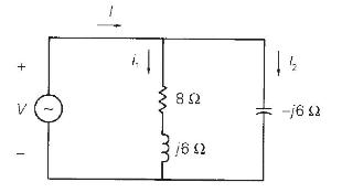
For the single-phase circuit shown in Figure 2.22, \(I=10 \angle 0^{\circ} \mathrm{A}\). (a) Compute the phasors \(I_{1}, I_{2}\), and \(V\). (b) Draw a phasor diagram showing \(I, I_{1}\), \(I_{2}\), and \(V\). 13 9!- 4 03 9/ 758 ^ +
A \(60-\mathrm{Hz}\), single-phase source with \(V=277 ot 30^{\circ}\) volts is applied to a circuit element.(a) Determine the instantaneous source voltage. Also determine the phasor and instantaneous currents entering the positive terminal if the circuit element is(b) a \(20-\Omega\) resistor,(c)
(a) Transform \(v(t)=75 \cos \left(377 t-15^{\circ}ight)\) to phasor form. Comment on whether \(\omega=377\) appears in your answer. (b) Transform \(V=50 / 10^{\circ}\) to instantaneous form. Assume that \(\omega=377\). (c) Add the two sinusoidal functions \(a(t)\) and \(b(t)\) of the same
Let a \(100-\mathrm{V}\) sinusoidal source be connected to a series combination of a \(3-\Omega\) resistor, an \(8-\Omega\) inductor, and a \(4-\Omega\) capacitor.(a) Draw the circuit diagram.(b) Compute the series impedance.(c) Determine the current \(I\) delivered by the source. Is the current
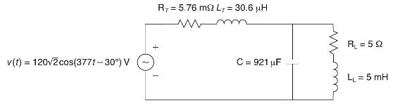
Consider the circuit shown in Figure 2.23 in time domain. Convert the entire circuit into phasor domain. v(t) = 120v2cos(377t-30) V R = 5.76 m2 L = 30.6 H C= : 921 uF R = 59 LL = 5 mH
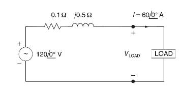
For the circuit shown in Figure 2.24, compute the voltage across the load terminals. + 0.192 /0.592 120/0 V 1 = 60/0 A VLOAD LOAD
For the circuit element of Problem 2.3, calculate(a) the instantaneous power absorbed,(b) the real power (state whether it is delivered or absorbed),(c) the reactive power (state whether delivered or absorbed),(d) the power factor (state whether lagging or leading).By convention the power factor
Referring to Problem 2.5, determine the instantaneous power, real power, and reactive power absorbed by(a) the \(20-\Omega\) resistor,(b) the \(10-\mathrm{mH}\) inductor,(c) the capacitor with \(25-\Omega\) reactance. Also determine the source power factor and state whether lagging or
The voltage \(v(t)=359.3 \cos (\omega t)\) volts is applied to a load consisting of a 10- resistor in parallel with a capacitive reactance \(X_{\mathrm{C}}=25 \Omega\). Calculate(a) the instantaneous power absorbed by the resistor,(b) the instantaneous power absorbed by the capacitor,(c) the real
Repeat Problem 2.12 if the resistor and capacitor are connected in series.Problem 2.12The voltage \(v(t)=359.3 \cos (\omega t)\) volts is applied to a load consisting of a 10- resistor in parallel with a capacitive reactance \(X_{\mathrm{C}}=25 \Omega\).
A single-phase source is applied to a two-terminal, passive circuit with equivalent impedance \(Z=3.0 \angle-45^{\circ} \Omega\), measured from the terminals. The source current is \(i(t)=2 \sqrt{2} \cos (\omega t) \mathrm{kA}\). Determine the (a) instantaneous power, (b) real power, (c) reactive
Let a voltage source \(v(t)=4 \cos \left(\omega t+60^{\circ}ight)\) be connected to an impedance \(Z=2 / 30^{\circ} \Omega\). (a) Given the operating frequency to be \(60 \mathrm{~Hz}\), determine the expressions for the current and instantaneous power delivered by the source as functions of time.
A single-phase, \(120-\mathrm{V}\) (rms), \(60-\mathrm{Hz}\) source supplies power to a series \(\mathrm{R}\) - \(\mathrm{L}\) circuit consisting of \(\mathrm{R}=10 \Omega\) and \(\mathrm{L}=40 \mathrm{mH}\).(a) Determine the power factor of the circuit and state whether it is lagging or
Consider a load impedance of \(Z=j \omega L\) connected to a voltage and \(V\) let the current drawn be \(I\).(a) Develop an expression for the reactive power \(\mathrm{Q}\) in terms of \(\omega, L\), and I, from complex power considerations.(b) Let the instantaneous current be \(i(t)=\sqrt{2}
Let a series RLC network be connected to a source voltage \(V\), drawing a current \(I\).(a) In terms of the load impedance \(Z=Z ot Z\), find expressions for \(\mathrm{P}\) and \(\mathrm{Q}\), from complex power considerations.(b) Express \(p(t)\) in terms of \(\mathrm{P}\) and \(\mathrm{Q}\), by
Consider a single-phase load with an applied voltage \(v(t)=150 \cos (\omega t+\) \(\left.10^{\circ}ight)\) volts and load current \(i(t)=5 \cos \left(\omega t-50^{\circ}ight) \mathrm{A}\). (a) Determine the power triangle. (b) Find the power factor and specify whether it is lagging or leading. (c)
A circuit consists of two impedances, \(Z_{1}=20 / 30^{\circ} \Omega\) and \(Z_{2}=25 / 60^{\circ} \Omega\), in parallel, supplied by a source voltage \(V=100 / 60^{\circ}\) volts. Determine the power triangle for each of the impedances and for the source.
An industrial plant consisting primarily of induction motor loads absorbs \(500 \mathrm{~kW}\) at 0.6 power factor lagging. (a) Compute the required \(\mathrm{kVA}\) rating of a shunt capacitor to improve the power factor to 0.9 lagging.(b) Calculate the resulting power factor if a synchronous
The real power delivered by a source to two impedances, \(Z_{1}=4+j 5 \Omega\) and \(Z_{2}=10 \Omega\), connected in parallel, is \(1000 \mathrm{~W}\). Determine (a) the real power absorbed by each of the impedances and (b) the source current.
A single-phase source has a terminal voltage \(V=120 / 0^{\circ}\) volts and a current \(I=15 / 30^{\circ}\) A, which leaves the positive terminal of the source. Determine the real and reactive power, and state whether the source is delivering or absorbing each.
A source supplies power to the following three loads connected in parallel: (1) a lighting load drawing \(10 \mathrm{~kW}\), (2) an induction motor drawing \(10 \mathrm{kVA}\) at 0.90 power factor lagging, and (3) a synchronous motor operating at \(10 \mathrm{hp}, 85 \%\) efficiency and 0.95 power
Consider the series RLC circuit of Problem 2.7 and calculate the complex power absorbed by each of the \(\mathrm{R}, \mathrm{L}\), and \(\mathrm{C}\) elements, as well as the complex power absorbed by the total load. Draw the resultant power triangle. Check whether the complex power delivered by
A small manufacturing plant is located \(2 \mathrm{~km}\) down a transmission line, which has a series reactance of \(0.5 \Omega / \mathrm{km}\). The line resistance is negligible. The line voltage at the plant is \(480 / 0^{\circ} \mathrm{V}\) (rms), and the plant consumes \(120 \mathrm{~kW}\) at
An industrial load consisting of a bank of induction motors consumes \(50 \mathrm{~kW}\) at a power factor of 0.8 lagging from a \(220-\mathrm{V}, 60-\mathrm{Hz}\), single-phase source. By placing a bank of capacitors in parallel with the load, the resultant power factor is to be raised to \(0.95
Three loads are connected in parallel across a single-phase source voltage of \(240 \mathrm{~V}\) (RMS).Load 1 absorbs \(15 \mathrm{~kW}\) and \(6.667 \mathrm{kvar}\);Load 2 absorbs \(3 \mathrm{kVA}\) at \(0.96 \mathrm{PF}\) leading;Load 3 absorbs \(15 \mathrm{~kW}\) at unity power factor.Calculate
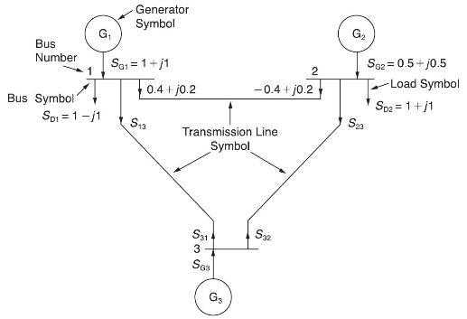
Modeling the transmission lines as inductors, with \(S_{i j}=S_{j i}^{*}\), Compute \(\mathrm{S}_{13}\), \(S_{31}, S_{23}, S_{32}\), and \(S_{G 3}\) in Figure 2.25. complex power balance holds good at each bus, satisfying KCL. Bus Number Bus Symbol G Generator Symbol SG1=1+/1 0.4+j0.2 Sp1=1/1 S13
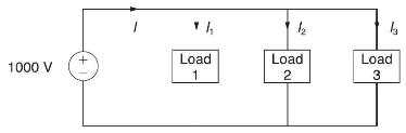
Figure 2.26 shows three loads connected in parallel across a \(1000-\mathrm{V}\) (RMS), 60-Hz single-phase source.Load 1: Inductive load, \(125 \mathrm{kVA}, 0.28 \mathrm{PF}\) lagging.Load 2: Capacitive load, \(10 \mathrm{~kW}, 40 \mathrm{kvar}\).Load 3: Resistive load, \(15 \mathrm{~kW}\).(a)
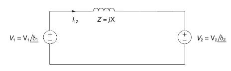
Consider two interconnected voltage sources connected by a line of impedance \(Z=j \mathrm{X} \Omega\), as shown in Figure 2.27.(a) Obtain expressions for \(\mathrm{P}_{12}\) and \(\mathrm{Q}_{12}\).(b) Determine the maximum power transfer and the condition for it to occur. V = V/81 1 + 112 m Z=jX
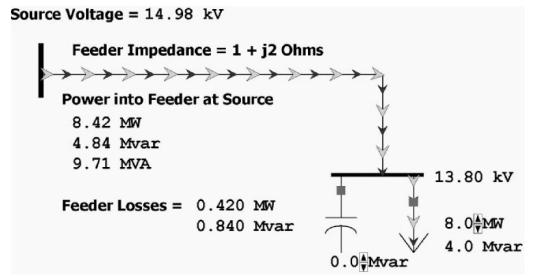
In PowerWorld Simulator case Problem 2_32 (see Figure 2.28) a 8 MW and 4 Mvar load is supplied at \(13.8 \mathrm{kV}\) through a feeder with an impedance of \(1+j 2 \Omega\). The load is compensated with a capacitor whose output, \(\Omega_{\text {cap }}\), can be varied is 0.5 Mvar steps between 0
For the system from Problem 2.32, plot the real and reactive line losses as Ωcap Ωcap is varied between 0 and 10.0 Mvars.Problem 2.32In PowerWorld Simulator case Problem 2_32 (see Figure 2.28) a 8 MW and 4 Mvar load is supplied at \(13.8 \mathrm{kV}\) through a feeder with an impedance of
For the system from Problem 2.32, assume that half the time the load is 10MW and 5 Mvar, and for the other half it is 20MW and 10 Mvar. What single value of Qcap would minimize the average losses? Assume that Qcap can only be varied in 0.5 Mvar steps.Problem 2.32In PowerWorld Simulator case
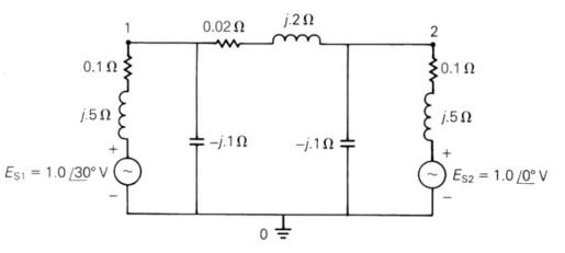
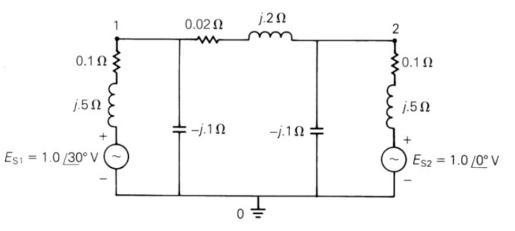
For the circuit shown in Figure 2.29, convert the voltage sources to equivalent current sources and write nodal equations in matrix format using bus 0 as the reference bus. Do not solve the equations. 0.102 j.50 Est = 1.0/30 V 0.02 -j.10 j.20 -j.10 = 2 0.102 1.50 Es2 = 1.0/0 V
For the circuit shown in Figure 2.29,(a) determine the \(2 \times 2\) bus admittance matrix \(\boldsymbol{Y}_{\text {bus }}\),(b) convert the voltage sources to current sources and determine the vector of source currents into buses 1 and 2. 0.1 15 Esi = 1.0 /30 V 0.02 -j.10 j.20 -j.10 of 2 20.1
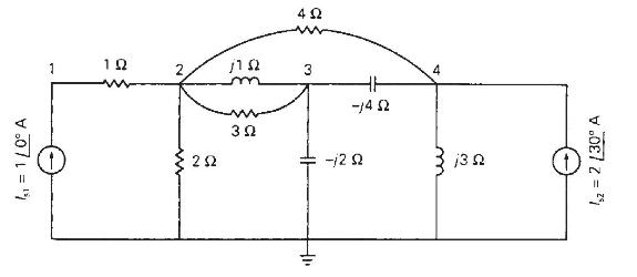
Determine the \(4 \times 4\) bus admittance matrix \(\boldsymbol{Y}_{\text {bus }}\) and write nodal equations in matrix format for the circuit shown in Figure 2.30. Do not solve the equations. 1 = 110 A 1 1 2 19 3 4 Ut 3 - -12 13 %z = 2 [30 A
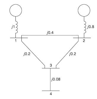
Given the impedance diagram of a simple system as shown in Figure 2.31, draw the admittance diagram for the system and develop the \(4 \times 4\) bus admittance matrix \(\boldsymbol{Y}_{\text {bus }}\) by inspection. am 1 j0.2 j0.4 3 | 10.08 4 10.2 2 10.8
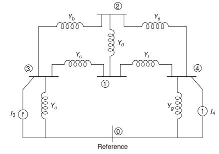
(a) Given the circuit diagram in Figure 2.32 showing admittances and current sources at nodes 3 and 4 , set up the nodal equations in matrix format.(b) If the parameters are given by: \(Y_{a}=-j 0.8 \mathrm{~S}, Y_{b}=-j 4.0 \mathrm{~S}\), \(Y_{c}=-j 4.0 \mathrm{~S}, Y_{d}=-j 8.0 \mathrm{~S},
A balanced three-phase \(240-\mathrm{V}\) source supplies a balanced three-phase load. If the line current \(I_{\mathrm{A}}\) is measured to be \(15 \mathrm{~A}\) and is in phase with the line-to-line voltage, \(V_{\mathrm{BC}}\), find the per-phase load impedance if the load is (a) Y-connected,
A three-phase \(25-\mathrm{kVA}, 480-\mathrm{V}, 60-\mathrm{Hz}\) alternator, operating under balanced steady-state conditions, supplies a line current of \(20 \mathrm{~A}\) per phase at a 0.8 lagging power factor and at rated voltage. Determine the power triangle for this operating condition.
A balanced \(\Delta\)-connected impedance load with \((12+j 9) \Omega\) per phase is supplied by a balanced three-phase \(60-\mathrm{Hz}, 208-\mathrm{V}\) source, (a) Calculate the line current, the total real and reactive power absorbed by the load, the load power factor, and the apparent load
A three-phase line, which has an impedance of \((2+j 4) \Omega\) per phase, feeds two balanced three-phase loads that are connected in parallel. One of the loads is Y-connected with an impedance of \((30+j 40) \Omega\) per phase, and the other is \(\Delta\)-connected with an impedance of \((60-j
Two balanced three-phase loads that are connected in parallel are fed by a three-phase line having a series impedance of \((0.4+j 2.7) \Omega\) per phase. One of the loads absorbs \(560 \mathrm{kVA}\) at 0.707 power factor lagging, and the other \(132 \mathrm{~kW}\) at unity power factor. The
Two balanced Y-connected loads, one drawing \(10 \mathrm{~kW}\) at 0.8 power factor lagging and the other \(15 \mathrm{~kW}\) at 0.9 power factor leading, are connected in parallel and supplied by a balanced three-phase Y-connected, \(480-\mathrm{V}\) source. (a) Determine the source current. (b)
Three identical impedances \(Z_{\Delta}=30 / 30^{\circ} \Omega\) are connected in \(\Delta\) to a balanced three-phase \(208-\mathrm{V}\) source by three identical line conductors with impedance \(Z_{\mathrm{L}}=(0.8+j 0.6) \Omega\) per line.(a) Calculate the line-to-line voltage at the load
Two three-phase generators supply a three-phase load through separate three-phase lines. The load absorbs \(30 \mathrm{~kW}\) at 0.8 power factor lagging. The line impedance is \((1.4+j 1.6) \Omega\) per phase between generator \(\mathrm{G}_{1}\) and the load, and \((0.8+j 1) \Omega\) per phase
Two balanced Y-connected loads in parallel, one drawing \(15 \mathrm{~kW}\) at 0.6 power factor lagging and the other drawing \(10 \mathrm{kVA}\) at 0.8 power factor leading, are supplied by a balanced, three-phase, 480 -volt source.(a) Draw the power triangle for each load and for the combined
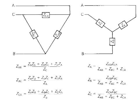
Figure 2.33 gives the general \(\Delta-Y\) transformation.(a) Show that the general transformation reduces to that given in Figure 2.16 for a balanced three-phase load.(b) Determine the impedances of the equivalent \(\mathrm{Y}\) for the following \(\Delta\) impedances: \(Z_{\mathrm{AB}}=j 10,
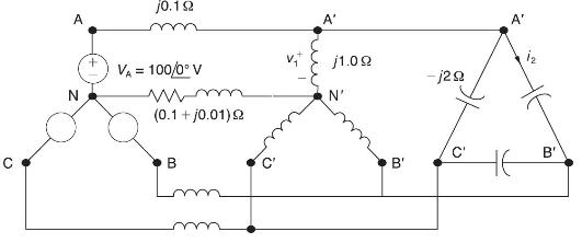
Consider the balanced three-phase system shown in Figure 2.34. Determine \(v_{1}(t)\) and \(i_{2}(t)\). Assume positive phase sequence. C A N j0.192 Va = 100/0 V wimm (0.1 + j001) 2 B A' j1.0g N' B' -j29 C' A' HE B'
A three-phase line with an impedance of \((0.2+j 1.0) \Omega /\) phase feeds three balanced three-phase loads connected in parallel.Load 1: Absorbs a total of \(150 \mathrm{~kW}\) and \(120 \mathrm{kvar}\).Load 2: Delta connected with an impedance of \((150-j 48) \Omega /\) phase.Load 3: \(120
A balanced three-phase load is connected to a \(4.16-\mathrm{kV}\), three-phase, fourwire, grounded-wye dedicated distribution feeder. The load can be modeled by an impedance of \(\mathrm{Z}_{\mathrm{L}}=(4.7+j 9) \Omega /\) phase, wye-connected. The impedance of the phase conductors is \((0.3+j 1)
The "Ohm's law" for the magnetic circuit states that the net magnetomotive force ( \(\mathrm{mmf}\) ) equals the product of the core reluctance and the core flux.(a) True(b) False
For an ideal transformer, the efficiency is(a) \(0 \%\)(b) \(100 \%\)(c) \(50 \%\)
For an ideal 2-winding transformer, the ampere-turns of the primary winding, \(N_{1} I_{1}\), is equal to the ampere-turns of the secondary winding, \(\mathrm{N}_{2} \mathrm{I}_{2}\)(a) True(b) False
An ideal transformer has no real or reactive power loss.(a) True(b) False
For an ideal 2-winding transformer, an impedance \(Z_{2}\) connected across winding 2 (secondary) is referred to winding 1 (primary) by multiplying \(Z_{2}\) by(a) The turns ratio \(\left(N_{1} / N_{2}ight)\)(b) The square of the turns ratio \(\left(N_{1} / N_{2}ight)^{2}\)(c) The cubed turns ratio
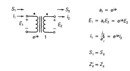
Consider Figure 3.4. For an ideal phase-shifting transformer, the impedance is unchanged when it is referred from one side to the other.(a) True(b) FalseFigure 3.4 S, - E + 3 || 1 E2 S2 + 2 = 8 E = arEz = ei#E2 | = = = eisla h S, = S 2 = 22
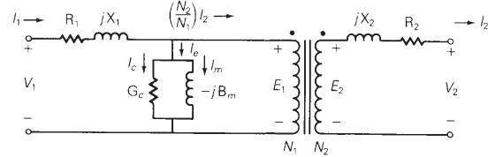
Consider Figure 3.5. Match the following, those on the left to those on the right.(i) ImIm(a) Exciting current(ii) IcIc(b) Magnetizing current(iii) IeIe(c) Core loss currentFigure 3.5 V R jX wwwm Ge (2) 12 -jBm + E N N E X 1320 R + V/
The units of admittance, conductance, and susceptance are siemens.(a) True(b) False
Match the following:(i) Hysteresis loss(ii) Eddy current loss(a) Can be reduced by constructing the core with laminated sheets of alloy steel(b) Can be reduced by the use of special high grades of alloy steel as core material.
For large power transformers rated more than \(500 \mathrm{kVA}\), the winding resistances, which are small compared with the leakage reactances, can often be neglected.(a) True(b) False
For a short-circuit test on a 2-winding transformer, with one winding shorted, can you apply the rated voltage on the other winding?(a) Yes(b) No
The per-unit quantity is always dimensionless.(a) True(b) False
Consider the adopted per-unit system for the transformers. Specify true or false for each of the following statements:(a) For the entire power system of concern, the value of \(S_{\text {base }}\) is not the same.(b) The ratio of the voltage bases on either side of a transformer is selected to be
The ideal transformer windings are eliminated from the per-unit equivalent circuit of a transformer.(a) True(b) False
To convert a per-unit impedance from "old" to "new" base values, the equation to be used is(a) \(Z_{\text {p.u.new }}=Z_{\text {p.u.old }}\left(\frac{\mathrm{V}_{\text {baseold }}}{\mathrm{V}_{\text {basenew }}}ight)^{2}\left(\frac{\mathrm{S}_{\text {basenew }}}{\mathrm{S}_{\text {baseold
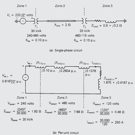
In developing per-unit circuits of systems such as the one shown in Figure 3.10, when moving across a transformer, the voltage base is changed in proportion to the transformer voltage ratings.(a) True(b) FalseFigure 3.10 V, 220/0 volts Zone 1 Vspu 0.9167/0 p.u. = Zbase 38 T 30 kVA 240/480 volts Xeq
Consider Figure 3.10 of the text. The per-unit leakage reactance of transformer \(T_{1}\), given as 0.1 p.u., is based on the name plate ratings of transformer \(T_{1}\).(a) True(b) FalseFigure 3.10 V, 220/0 volts Zone 1 Vspu 0.9167/0 p.u. = Zbase 38 T 30 kVA 240/480 volts Xeq = 0.10 p.u. Zone 1
For balanced three-phase systems, \(\mathrm{Z}_{\text {base }}\) is given by(a) True(b) False Zbase baseLL Sbase3
With the American Standard notation, in either a \(\mathrm{Y}-\Delta\) or \(\Delta-\mathrm{Y}\) transformer, positive- sequence quantities on the high-voltage side shall lead their corresponding quantities on the low-voltage side by \(30^{\circ}\).(a) True(b) False
In either a \(\mathrm{Y}-\Delta\) or \(\Delta-\mathrm{Y}\) transformer, as per the American Standard notation, the negative-sequence phase shift is the reverse of the positivesequence phase shift.(a) True(b) False
In order to avoid difficulties with third-harmonic exciting current, which three-phase transformer connection is seldom used for step-up transformers between a generator and a transmission line in power systems.(a) \(\mathrm{Y}-\Delta\)(b) \(\Delta-\mathrm{Y}\)(c) \(\mathrm{Y}-\mathrm{Y}\)
Showing 3600 - 3700
of 5433
First
30
31
32
33
34
35
36
37
38
39
40
41
42
43
44
Last
Step by Step Answers