New Semester
Started
Get
50% OFF
Study Help!
--h --m --s
Claim Now
Question Answers
Textbooks
Find textbooks, questions and answers
Oops, something went wrong!
Change your search query and then try again
S
Books
FREE
Study Help
Expert Questions
Accounting
General Management
Mathematics
Finance
Organizational Behaviour
Law
Physics
Operating System
Management Leadership
Sociology
Programming
Marketing
Database
Computer Network
Economics
Textbooks Solutions
Accounting
Managerial Accounting
Management Leadership
Cost Accounting
Statistics
Business Law
Corporate Finance
Finance
Economics
Auditing
Tutors
Online Tutors
Find a Tutor
Hire a Tutor
Become a Tutor
AI Tutor
AI Study Planner
NEW
Sell Books
Search
Search
Sign In
Register
study help
computer science
systems analysis design
Power System Analysis And Design 6th Edition J. Duncan Glover, Thomas Overbye, Mulukutla S. Sarma - Solutions
Repeat Problem 7.24, except place the fault at bus 4.Problem 7.24 PowerWorld Simulator case Problem 7_24 models the system shown in Figure 7.14 with all data on a 1000 MVA base. Using PowerWorld Simulator, determine the current supplied by each generator and the per-unit bus voltage magnitudes at
Repeat Problem 7.24, except place the fault midway between buses 2 and 3 . Determining the values for line faults requires that the line be split with a fictitious bus added at the point of the fault. The original line's impedance is then allocated to the two new lines based on the fault location,
One technique for limiting fault current is to place reactance in series with the generators. Such reactance can be modeled in PowerWorld Simulator by increasing the value of the generator's positive sequence internal impedance. For the Problem 7.24 case, how much per-unit reactance must be added
Using PowerWorld Simulator case Example 6_13, determine the per-unit current and actual current in amps supplied by each of the generators for a fault at the POPLAR69 bus. During the fault, what percentage of the system buses have voltage magnitudes below 0.75 per unit?Example 6_13To see a power
Repeat Problem 7.28, except place the fault at the REDBUD69 bus.Problem 7.28Using PowerWorld Simulator case Example 6_13, determine the per-unit current and actual current in amps supplied by each of the generators for a fault at the POPLAR69 bus. During the fault, what percentage of the system
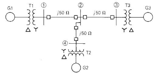
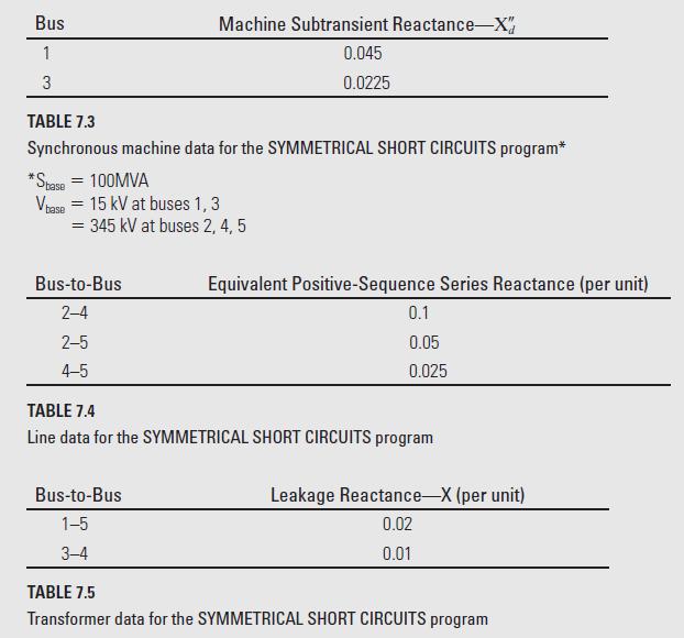
Using PowerWorld Simulator case Example 7_5, open the line connecting buses 4 and 5 . Then, determine the per unit current supplied by the generator at bus 3 due a fault at bus 2.Example 7_5PowerWorld Simulator case Example 7_5 models the 5-bus power system whose oneline diagram is shown in Figure
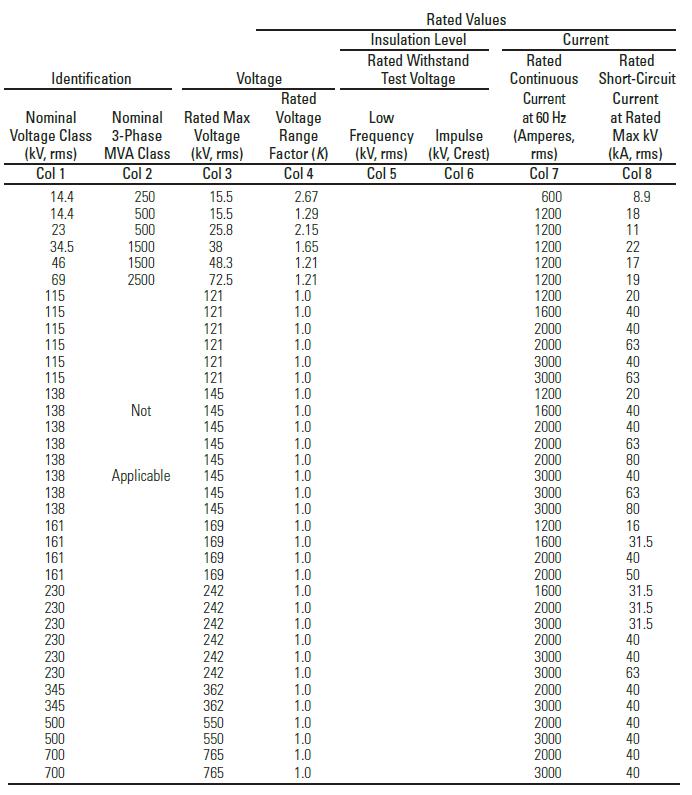
A three-phase circuit breaker has a \(15.5-\mathrm{kV}\) rated maximum voltage, \(9.0-\mathrm{kA}\) rated short-circuit current, and a 2.50-rated voltage range factor. (a) Determine the symmetrical interrupting capability at \(10-\mathrm{kV}\) and \(5-\mathrm{kV}\) operating voltages. (b) Can this
A \(345-\mathrm{kV}\), three-phase transmission line has a 2.2-kA continuous current rating and a \(2.5-\mathrm{kA}\) maximum short-time overload rating with a \(356-\mathrm{kV}\) maximum operating voltage. The maximum symmetrical fault current on the line is \(30 \mathrm{kA}\). Select a circuit
A \(69-\mathrm{kV}\) circuit breaker has a voltage range factor \(\mathrm{K}=1.25\), a continuous current rating of \(1200 \mathrm{~A}\), and a rated short-circuit current of 19,000 A at the maximum rated voltage of \(72.5 \mathrm{kV}\). Determine the maximum symmetrical interrupting capability of
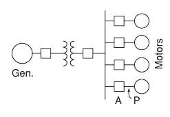
As shown in Figure 7.21, a 25-MVA, 13.8-kV, 60-Hz, synchronous generator with \(\mathrm{X}_{d}{ }^{\prime \prime}=0.15\) per unit is connected through a transformer to a bus that supplies four identical motors. The rating of the three-phase transformer is 25 MVA and \(13.8 / 6.9 \mathrm{kV}\) with
Positive-sequence components consist of three phasors with _________ magnitudes and _________ phase displacement in positive sequence; negativesequence components consist of three phasors with _________ magnitudes and _________ phase displacement in negative sequence; and zero-sequence components
In symmetrical-component theory, express the complex-number operator \(a=1 \angle 120^{\circ}\) in exponential and rectangular forms.
In terms of sequence components of phase \(a\) given by \(V_{a 0}=V_{0}, V_{a 1}=V_{1}\), and \(V_{a 2}=V_{2}\), give expressions for the phase voltages \(V_{a}, V_{b}\), and \(V_{c}\). \(V_{a}=\)_______________ \(; V_{b}=\) _______________ \(; V_{c}=\)_______________.
The sequence components \(V_{0}, V_{1}\), and \(V_{2}\) can be expressed in terms of phase components \(V_{a}, V_{b}\), and \(V_{c}\).\(V_{0}=\) _______________; \(V_{1}=\)_______________ \(; V_{2}=\)_______________.
In a balanced three-phase system, what is the zero-sequence voltage? \(V_{0}=\)_______________.
In an unbalanced three-phase system, line-to-neutral voltage _____________ have a zero-sequence component, whereas line-to-line voltages ____________ have a zero-sequence component.
Can the symmetrical component transformation be applied to currents, just as it is applied to voltages?(a) Yes(b) No
In a three-phase Y-connected system with a neutral, express the neutral current in terms of phase currents and sequence-component terms.\(I_{n}=\)____________ \(=\)____________.
In a balanced Y-connected system, what is the zero-sequence component of the line currents?
In a \(\Delta\)-connected three-phase system, line currents have no zero-sequence component.(a) True(b) False
Balanced three-phase systems with positive sequence do not have zerosequence and negative-sequence components.(a) True(b) False
Unbalanced three-phase systems may have nonzero values for all sequence components.(a) True(b) False
For a balanced- \(Y\) impedance load with per-phase impedance of \(Z_{Y}\) and a neutral impedance \(Z_{n}\) connected between the load neutral and the close space ground, the \(3 \times 3\) phase-impedance matrix consists of equal diagonal elements given by ____________ and equal nondiagonal
Express the sequence impedance matrix \(Z_{\mathrm{S}}\) in terms of the phaseimpedance matrix \(\boldsymbol{Z}_{\mathrm{P}}\), and the transformation matrix \(\boldsymbol{A}\) which relates \(\boldsymbol{V}_{\mathrm{P}}=\boldsymbol{A} \boldsymbol{V}_{\mathrm{S}}\) and
The sequence impedance matrix \(Z_{S}\) for a balanced- \(Y\) load is a diagonal matrix and the sequence networks are uncoupled.(a) True(b) False
For a balanced-Y impedance load with per-phase impedance of \(Z_{Y}\) and a neutral impedance \(Z_{n}\), the zero-sequence voltage \(V_{0}=Z_{0} I_{0}\), where \(Z_{0}=\)____________.
For a balanced- \(\Delta\) load with per-phase impedance of \(Z_{\Delta}\), the equivalent Y-load has an open neutral; for the corresponding uncoupled sequence networks, \(Z_{0}=\)____________ \(Z_{1}=\) ____________, and \(Z_{2}=\)____________.
For a three-phase symmetrical impedance load, the sequence impedance matrix is and hence the sequence networks are (a) coupled or (b) uncoupled.
Sequence networks for three-phase symmetrical series impedances are (a) coupled or (b) uncoupled; positive-sequence currents produce only ____________ voltage drops.
The series-sequence impedance matrix of a completely transposed three-phase line is ____________ with its nondiagonal elements equal to ____________.
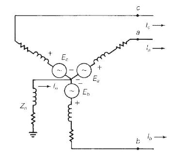
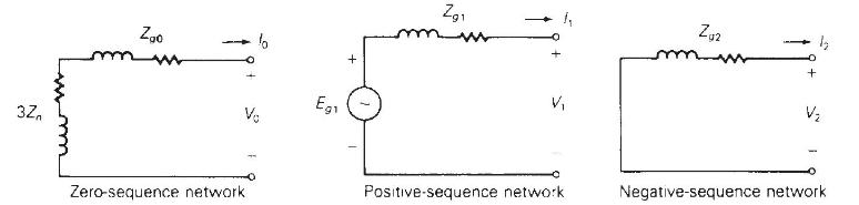
A Y-connected synchronous generator grounded through a neutral impedance \(Z_{n}\) with a zero-sequence impedance \(Z_{g 0}\)____________ has zero-sequence impedance \(Z_{0}=\) in its zero-sequence network.
In sequence networks, a Y-connected synchronous generator is represented by its source per-unit voltage only in ____________ network, while (a) synchronous, (b) transient or (c) sub-transient impedance is used in positive-sequence network for short-circuit studies.
In the positive-sequence network of a synchronous motor, a source voltage is represented, whereas in that of an induction motor, the source voltage (a) does or (b) does not come into picture.
With symmetrical components, the conversion from phase to sequence components decouples the networks and the resulting KVL equations.(a) True(b) False
Consider the per-unit sequence networks of \(\mathrm{Y}-\mathrm{Y}, \mathrm{Y}-\Delta\), and \(\Delta-\Delta\) transformers with neutral impedances of \(Z_{N}\) on the high-voltage Y-side and \(Z_{n}\) on the low-voltage Y-side. Answer the following:(i) Zero-sequence currents (a) can or (b) cannot
In per-unit sequence models of three-phase three-winding transformers, for the general zero-sequence network, the connection between terminals \(\mathrm{H}\) and \(\mathrm{H}^{\prime}\) depends on how the high-voltage windings are connected:(i) For solidly grounded Y, ____________ \(\mathrm{H}\) to
The total complex power delivered to a three-phase network equals (a) 1, (b) 2, or (c) 3 times the total complex power delivered to the sequence networks.
Express the complex power \(S_{\mathrm{S}}\) delivered to the sequence networks in terms of sequence voltages and sequence currents, where \(S_{\mathrm{S}}=\)
Using the operator \(a=1 / 120^{\circ}\), evaluate the following in polar form:(a) \((a-1) /\left(1+a-a^{2}ight)\),(b) \(\left(a^{2}+a+jight) /\left(j a+a^{2}ight)\),(c) \((1+a)\left(1+a^{2}ight)\), and(d) \(\left(a-a^{2}ight)\left(a^{2}-1ight)\).
Using \(a=1 \angle 120^{\circ}\), evaluate the following in rectangular form:a. \(a^{10}\)b. \((j a)^{10}\)c. \((1-a)^{3}\)d. \(\mathrm{e}^{a}\)
Determine the symmetrical components of the following line currents: (a) \(I_{a}=6 \angle 90^{\circ}, I_{b}=6 \angle 320^{\circ}, I_{c}=6 \angle 220^{\circ} \mathrm{A}\) and (b) \(I_{a}=j 40, I_{b}=40, I_{c}=0 \mathrm{~A}\).
Find the phase voltages \(V_{a n}, V_{b n}\), and \(V_{c n}\) whose sequence components are \(V_{0}=45 \angle 80^{\circ}, V_{1}=90 \angle 0^{\circ}, V_{2}=45 \angle 90^{\circ} \mathrm{V}\).
For the unbalanced three-phase system described by\[I_{a}=10 \angle 0^{\circ} \mathrm{A}, I_{b}=8 \angle-90^{\circ} \mathrm{A}, I_{\mathrm{c}}=6 \angle 150^{\circ} \mathrm{A}\]compute the symmetrical components \(I_{0}, I_{1}\), and \(I_{2}\).
(a) Given the symmetrical components to be\[V_{0}=10 \angle 0^{\circ} \mathrm{V}, V_{1}=80 \angle 30^{\circ} \mathrm{V}, V_{2}=40 \angle-30^{\circ} \mathrm{V}\]determine the unbalanced phase voltages \(V_{a}, V_{b}\), and \(V_{c}\).(b) Using the results of part (a), calculate the line-to-line
One line of a three-phase generator is open-circuited, while the other two are short-circuited to ground. The line currents are \(I_{a}=0, I_{b}=1200 \angle 150^{\circ}\), and \(I_{c}=1200 \angle+30^{\circ} \mathrm{A}\). Find the symmetrical components of these currents. Also find the current into
Let an unbalanced, three-phase, Y-connected load (with phase impedances of \(Z_{a}, Z_{b}\), and \(Z_{c}\) ) be connected to a balanced three-phase supply, resulting in phase voltages of \(V_{a}, V_{b}\), and \(V_{c}\) across the corresponding phase impedances.Choosing \(V_{a b}\) as the reference,
Reconsider Problem 8.8 and choosing \(V_{b c}\) as the reference, show that\[V_{b c, 0}=0 ; \quad V_{b c, 1}=-j \sqrt{3} V_{a, 1} ; \quad V_{b c, 2}=j \sqrt{3} V_{a, 2}\]Problem 8.8Let an unbalanced, three-phase, Y-connected load (with phase impedances of \(Z_{a}, Z_{b}\), and \(Z_{c}\) ) be
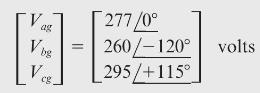
Given the line-to-ground voltages \(V_{a g}=280 \angle 0^{\circ}, V_{b g}=250 \angle-110^{\circ}\), and \(V_{c g}=290 \angle 130^{\circ}\) volts, calculate (a) the sequence components of the lineto-ground voltages, denoted \(V_{\mathrm{Lg} 0}, V_{\mathrm{Lg} 1}\) and \(V_{\mathrm{Lg} 2}\); (b)
A balanced \(\Delta\)-connected load is fed by a three-phase supply for which phase \(\mathrm{C}\) is open and phase \(\mathrm{A}\) is carrying a current of \(10 \angle 0^{\circ} \mathrm{A}\). Find the symmetrical components of the line currents. (Note that zero-sequence currents are not present
A Y-connected load bank with a three-phase rating of \(500 \mathrm{kVA}\) and \(2300 \mathrm{~V}\) consists of three identical resistors of \(10.58 \Omega\). The load bank has the following applied voltages: \(V_{a b}=1840 \angle 82.8^{\circ}, V_{b c}=2760 \angle-41.4^{\circ}\), and \(V_{c a}=2300
The currents in a \(\Delta\) load are \(I_{a b}=10 \angle 0^{\circ}, I_{b c}=12 \angle-90^{\circ}\), and \(I_{c a}=15 \angle 90^{\circ} \mathrm{A}\). Calculate (a) the sequence components of the \(\Delta\)-load currents, denoted \(I_{\Delta 0}, I_{\Delta 1}\), and \(I_{\Delta 2}\); (b) the line
The voltages given in Problem 8.10 are applied to a balanced-Y load consisting of \((12+j 16)\) ohms per phase. The load neutral is solidly grounded. Draw the sequence networks and calculate \(I_{0}, I_{1}\), and \(I_{2}\), the sequence components of the line currents. Then calculate the line
Repeat Problem 8.14 with the load neutral open.Problem 8.14Given the line-to-ground voltages \(V_{a g}=280 \angle 0^{\circ}, V_{b g}=250 \angle-110^{\circ}\), and \(V_{c g}=290 \angle 130^{\circ}\) volts, calculate (a) the sequence components of the lineto-ground voltages, denoted \(V_{\mathrm{Lg}
Repeat Problem 8.14 for a balanced- \(\Delta\) load consisting of \((12+j 16)\) ohms per phase.Problem 8.14Given the line-to-ground voltages \(V_{a g}=280 \angle 0^{\circ}, V_{b g}=250 \angle-110^{\circ}\), and \(V_{c g}=290 \angle 130^{\circ}\) volts, calculate (a) the sequence components of the
Repeat Problem 8.14 for the load shown in Example 8.4.Problem 8.14Given the line-to-ground voltages \(V_{a g}=280 \angle 0^{\circ}, V_{b g}=250 \angle-110^{\circ}\), and \(V_{c g}=290 \angle 130^{\circ}\) volts, calculate (a) the sequence components of the lineto-ground voltages, denoted
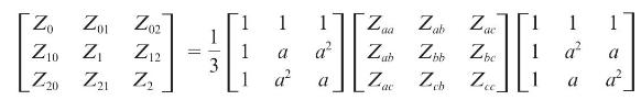
Perform the indicated matrix multiplications in (8.2.21) and verify the sequence impedances given by (8.2.22) through (8.2.27).Eq. (8.2.21)Eq. (8.2.22)Eq. (8.2.27) Zo Zab Zac 1 1 a Zbb Zbc 1 3 Z Z 1 a ac 1 a Z Z Z a
The following unbalanced line-to-ground voltages are applied to the balanced-Y load shown in Figure 3.3: \(V_{a g}=100 \angle 0^{\circ}, V_{b g}=75 \angle 180^{\circ}\), and \(V_{c g}=50 \angle 90^{\circ}\) volts. The \(\mathrm{Y}\) load has \(Z_{\mathrm{Y}}=3+j 4 \Omega\) per phase with neutral
(a) Consider three equal impedances of (j27) \(\Omega\) connected in \(\Delta\). Obtain the sequence networks.(b) Now, with a mutual impedance of (j6) \(\Omega\) between each pair of adjacent branches in the \(\Delta\)-connected load of part (a), how would the sequence networks change?
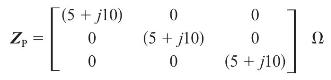
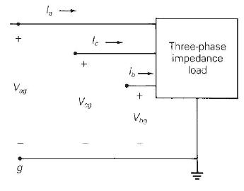
The three-phase impedance load shown in Figure 8.7 has the following phase impedance matrix:Determine the sequence impedance matrix \(Z_{\mathrm{S}}\) for this load. Is the load symmetrical?Figure 8.7 Zp || (5 +j10) 0 0 0 (5 + j10) 0 0 0 (5 + j10)
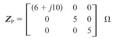
The three-phase impedance load shown in Figure 8.7 has the following sequence impedance matrix:Determine the phase impedance matrix \(Z_{\mathrm{P}}\) for this load. Is the load symmetrical?Figure 8.7 (6+j10) 0 07 0 0 50 05
Consider a three-phase balanced Y-connected load with self and mutual impedances as shown in Figure 8.23. Let the load neutral be grounded through an impedance \(Z_{n}\). Using Kirchhoff's laws, develop the equations for line-to-neutral voltages, and then determine the elements of the phase
A three-phase balanced voltage source is applied to a balanced Y-connected load with ungrounded neutral. The Y-connected load consists of three mutually coupled reactances, where the reactance of each phase is \(j 12 \Omega\), and the mutual coupling between any two phases is \(j 4 \Omega\). The
A three-phase balanced Y-connected load with series impedances of \((6+j 24) \Omega\) per phase and mutual impedance between any two phases of \(j 3 \Omega\) is supplied by a three-phase unbalanced source with line-to-neutral voltages of \(V_{a n}=200 \angle 25^{\circ}, V_{b n}=100
Repeat Problem 8.14 but include balanced three-phase line impedances of \((3+j 4)\) ohms per phase between the source and load.Problem 8.14The voltages given in Problem 8.10 are applied to a balanced-Y load consisting of \((12+j 16)\) ohms per phase. The load neutral is solidly grounded. Draw the
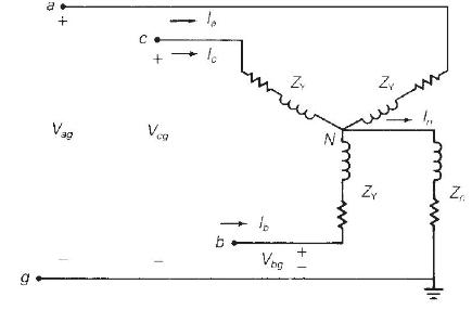
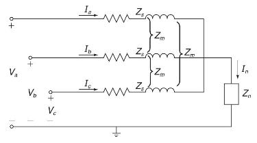
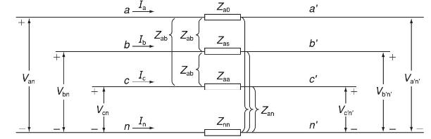
Consider the flow of unbalanced currents in the symmetrical three-phase line section with neutral conductor as shown in Figure 8.24. (a) Express the voltage drops across the line conductors given by \(V_{a a}, V_{b b}\), and \(V_{c c}\) in terms of line currents, self-impedances defined by
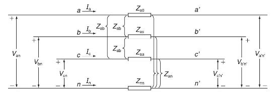
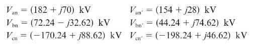
Let the terminal voltages at the two ends of the line section shown in Figure 8.24 be given byThe line impedances are given by:\[Z_{\mathrm{aa}}=j 60 \Omega \quad Z_{\mathrm{ab}}=j 20 \Omega \quad Z_{\mathrm{nn}}=j 80 \Omega \quad Z_{\mathrm{an}}=0 \](a) Compute the line currents using symmetrical
A completely transposed three-phase transmission line of \(200 \mathrm{~km}\) in length has the following symmetrical sequence impedances and sequence admittances:\[\begin{aligned}& Z_{1}=Z_{2}=j 0.5 \Omega / \mathrm{km} ; \quad Z_{0}=j 2 \Omega / \mathrm{km} \\& Y_{1}=Y_{2}=j 3 \times 10^{-9}
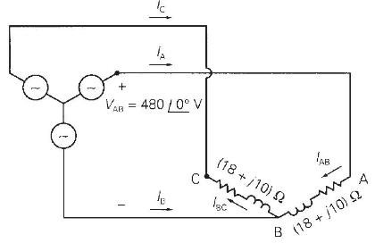
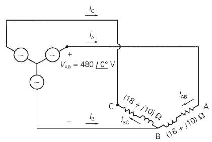
As shown in Figure 8.25, a balanced three-phase, positive-sequence source with \(V_{\mathrm{AB}}=480 \angle 0^{\circ}\) volts is applied to an unbalanced \(\Delta\) load. Note that one leg of the \(\Delta\) is open. Determine (a) the load currents \(I_{\mathrm{AB}}\) and \(I_{\mathrm{BC}}\); (b)
A balanced Y-connected generator with terminal voltage \(V_{b c}=200 \angle 0^{\circ}\) volts is connected to a balanced- \(\Delta\) load whose impedance is \(10 / 40^{\circ} \mathrm{ohms}\) per phase. The line impedance between the source and load is \(0.5 / 80^{\circ}\) ohm for each phase. The
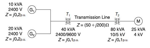
In a three-phase system, a synchronous generator supplies power to a 200 -volt synchronous motor through a line having an impedance of \(0.5 ot 80^{\circ}\) ohm per phase. The motor draws \(5 \mathrm{~kW}\) at 0.8 p.f. leading and at rated voltage. The neutrals of both the generator and motor are
Calculate the source currents in Example 8.6 without using symmetrical components. Compare your solution method with that of Example 8.6. Which method is easier?Example 8.6A Y-connected voltage source with the following unbalanced voltage is applied to the balanced line and load of Example 2.4.The
A Y-connected synchronous generator rated \(20 \mathrm{MVA}\) at \(13.8 \mathrm{kV}\) has a positive-sequence reactance of \(j 2.38 \Omega\), negative-sequence reactance of \(j 3.33 \Omega\), and zero-sequence reactance of \(j 0.95 \Omega\). The generator neutral is solidly grounded. With the
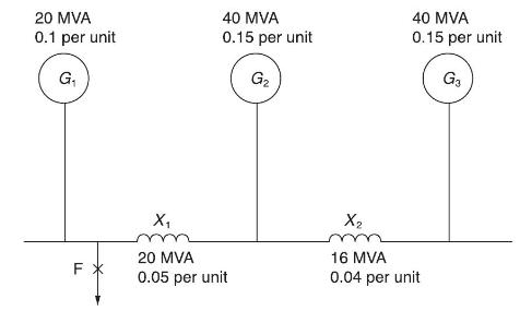
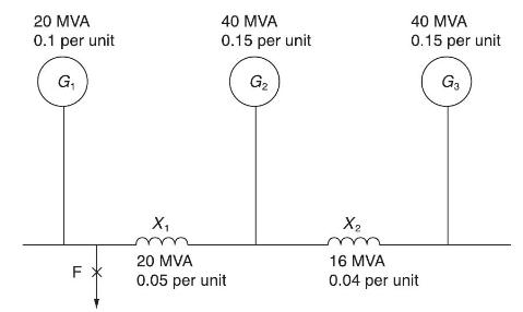
Figure 8.26 shows a single-line diagram of a three-phase, interconnected generator-reactor system, in which the given per-unit reactances are based on the ratings of the individual pieces of equipment. If a threephase short-circuit occurs at fault point F, obtain the fault MVA and fault current in
Consider Figures 8.13 and 8.14 of the text with reference to a Y-connected synchronous generator (grounded through a neutral impedance \(Z_{n}\) ) operating at no load. For a line-to-ground fault occurring on phase \(a\) of the generator, list the constraints on the currents and voltages in the
Reconsider the synchronous generator of Problem 8.36. Obtain sequencenetwork representations for the following fault conditions.(a) A short-circuit between phases \(b\) and \(c\).(b) A double line-to-ground fault with phases \(b\) and \(c\) grounded.Problem 8.36Consider Figures 8.13 and 8.14 of the
Three single-phase, two-winding transformers, each rated 450 MVA, \(20 \mathrm{kV} / 288.7 \mathrm{kV}\), with leakage reactance \(X_{\text {eq }}=0.12\) per unit, are connected to form a three-phase bank. The high-voltage windings are connected in Y with a solidly grounded neutral. Draw the
The leakage reactance of a three-phase, 500-MVA, \(345 \mathrm{Y} / 23 \Delta-\mathrm{kV}\) transformer is 0.09 per unit based on its own ratings. The \(\mathrm{Y}\) winding has a solidly grounded neutral. Draw the sequence networks. Neglect the exciting admittance and assume American standard
Choosing system bases to be \(360 / 24 \mathrm{kV}\) and 100 MVA, redraw the sequence networks for Problem 8.39.Problem 8.39The leakage reactance of a three-phase, 500-MVA, \(345 \mathrm{Y} / 23 \Delta-\mathrm{kV}\) transformer is 0.09 per unit based on its own ratings. The \(\mathrm{Y}\) winding
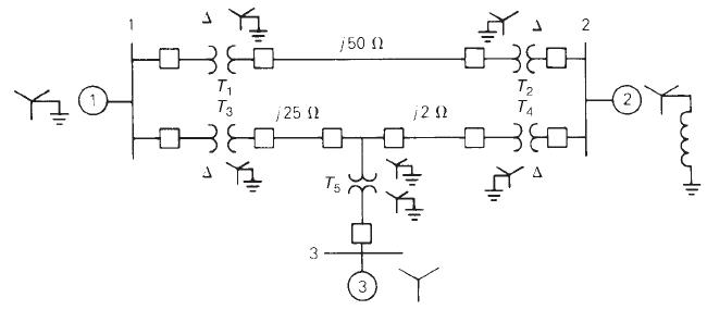
Draw the zero-sequence reactance diagram for the power system shown in Figure 3.38. The zero-sequence reactance of each generator and of the synchronous motor is 0.05 per unit based on equipment ratings. Generator 2 is grounded through a neutral reactor of 0.06 per unit on a \(100-\mathrm{MVA},
Three identical Y-connected resistors of \(1.0 \angle 0^{\circ}\) per unit form a load bank that is supplied from the low-voltage Y-side of a Y- \(\Delta\) transformer. The neutral of the load is not connected to the neutral of the system. The positive- and negative-sequence currents flowing toward
Draw the positive-, negative-, and zero-sequence circuits for the transformers shown in Figure 3.34. Include ideal phase-shifting transformers showing phase shifts. Assume that all windings have the same \(\mathrm{kVA}\) rating and that the equivalent leakage reactance of any two windings with the
For Problem 8.14, calculate the real and reactive power delivered to the three-phase load.Problem 8.14Given the line-to-ground voltages \(V_{a g}=280 \angle 0^{\circ}, V_{b g}=250 \angle-110^{\circ}\), and \(V_{c g}=290 \angle 130^{\circ}\) volts, calculate (a) the sequence components of the
A three-phase impedance load consists of a balanced- \(\Delta\) load in parallel with a balanced-Y load. The impedance of each leg of the \(\Delta\) load is \(Z_{\Delta}=\) \(6+j 6 \Omega\), and the impedance of each leg of the Y load is \(Z_{Y}=2+j 2 \Omega\). The Y load is grounded through a
For Problem 8.12, compute the power absorbed by the load using symmetrical components. Then verify the answer by computing directly without using symmetrical components.Problem 8.12A Y-connected load bank with a three-phase rating of \(500 \mathrm{kVA}\) and \(2300 \mathrm{~V}\) consists of three
For Problem 8.25, determine the complex power delivered to the load in terms of symmetrical components. Verify the answer by adding up the complex power of each of the three phases.Problem 8.25A three-phase balanced Y-connected load with series impedances of \((6+j 24) \Omega\) per phase and mutual
Using the voltages of Problem 8.6(a) and the currents of Problem 8.5, compute the complex power dissipated based on(a) phase components and(b) symmetrical components.Problem 8.6(a)Given the symmetrical components to be\[V_{0}=10 \angle 0^{\circ} \mathrm{V}, V_{1}=80 \angle 30^{\circ} \mathrm{V},
For power-system fault studies, it is assumed that the system is operating under balanced steady-state conditions prior to the fault, and sequence networks are uncoupled before the fault occurs.(a) True(b) False
The first step in power-system fault calculations is to develop sequence networks based on the single-line diagram of the system, and then reduce them to their Thévenin equivalents, as viewed from the fault location.(a) True(b) False
When calculating symmetrical three-phase fault currents, only _________ sequence network needs to be considered.
In order of frequency of occurrence of short-circuit faults in three-phase power systems, list those: _________, _________, _________, _________.
For a bolted three-phase-to-ground fault, sequence-fault currents _________ are zero, sequence fault voltages are _________, and line-to-ground voltages are _________.
For a single-line-to-ground fault with a fault-impedance \(Z_{\mathrm{F}}\), the sequence networks are to be connected _________ at the fault terminals through the impedance ; the sequence components of the fault currents are _________.
For a line-to-line fault with a fault impedance \(Z_{\mathrm{F}}\), the positive-and negative-sequence networks are to be connected _________ at the fault terminals through the impedance of \(1 / 2 / 3\) times \(Z_{\mathrm{F}}\); the zero-sequence current is _________.
For a double line-to-ground fault through a fault impedance \(Z_{\mathrm{F}}\), the sequence networks are to be connected _________ at the fault terminal; additionally, _________ is to be included in series with the zero-sequence network.
The sequence bus-impedance matrices can also be used to calculate fault currents and voltages for symmetrical as well as unsymmetrical faults by representing each sequence network as a bus-impedance rake-equivalent circuit.(a) True(b) False
The rms value of \(v(t)=\mathrm{V}_{\text {max }} \cos (\omega t+\delta)\) is given by(a) \(\mathrm{V}_{\max }\)(b) \(\mathrm{V}_{\max } / \sqrt{2}\)(c) \(2 \mathrm{~V}_{\max }\)(d) \(\sqrt{2} \mathrm{~V}_{\max }\)
If the rms phasor of a voltage is given by \(\mathrm{V}=120 / 60^{\circ}\) volts, then the corresponding \(v(t)\) is given by(a) \(120 \sqrt{2} \cos \left(\omega t+60^{\circ}ight)\)(b) \(120 \cos \left(\omega t+60^{\circ}ight)\)(c) \(120 \sqrt{2} \sin \left(\omega r+60^{\circ}ight)\)
If a phasor representation of a current is given by \(I=70.7 \angle 45^{\circ} \mathrm{A}\), it is equivalent to(a) \(100 e^{j 45^{\circ}}\)(b) \(100+j 100\)(c) \(50+j 50\)
With sinusoidal-steady-state excitation, for a purely resistive circuit, the voltage and current phasors are(a) In phase(b) Perpendicular with each other with \(V\) leading \(I\) (v) Perpendicular with each other with \(I\) leading \(V\).
For a purely inductive circuit, with sinusoidal-steady-state excitation, the voltage and current phasors are(a) In phase(b) Perpendicular to each other with \(V\) leading \(I\)(c) Perpendicular to each other with \(I\) leading \(V\).
Showing 3500 - 3600
of 5433
First
29
30
31
32
33
34
35
36
37
38
39
40
41
42
43
Last
Step by Step Answers