New Semester
Started
Get
50% OFF
Study Help!
--h --m --s
Claim Now
Question Answers
Textbooks
Find textbooks, questions and answers
Oops, something went wrong!
Change your search query and then try again
S
Books
FREE
Study Help
Expert Questions
Accounting
General Management
Mathematics
Finance
Organizational Behaviour
Law
Physics
Operating System
Management Leadership
Sociology
Programming
Marketing
Database
Computer Network
Economics
Textbooks Solutions
Accounting
Managerial Accounting
Management Leadership
Cost Accounting
Statistics
Business Law
Corporate Finance
Finance
Economics
Auditing
Tutors
Online Tutors
Find a Tutor
Hire a Tutor
Become a Tutor
AI Tutor
AI Study Planner
NEW
Sell Books
Search
Search
Sign In
Register
study help
engineering
chemical reaction engineering
Chemical Reaction Engineering 3rd Edition Octave Levenspiel - Solutions
A reaction has the stoichiometric equation A + B = 2R. What is the order of reaction?
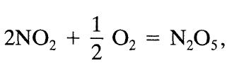
Given thatwhat is the relation between the rates of formation and disappearance of the three reaction components? 1/1/0₂ = N₂O5, 2 2NO₂ +
For the complex reaction with stoichiometry A + 3B → 2R + S and with second-order rate expressionare the reaction rates related as follows: rA, = rB, = rR,? If the rates are not so related, then how are they related? account for the signs, + or -. -TA = k₁[A][B]
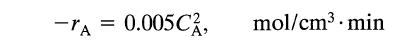
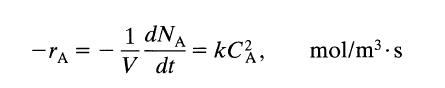
A certain reaction has a rate given byIf the concentration is to be expressed in mollliter and time in hours, what would be the value and units of the rate constant? -TA = 0.005 C, mol/cm³. min
On doubling the concentration of reactant, the rate of reaction triples. Find the reaction order.
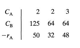
For the stoichiometry A + B → (products) find the reaction orders with respect to A and B. CA CB -IA 2 2 3 125 64 64 50 32 48
Mechanism for enzyme catalyzed reactions. To explain the kinetics of enzyme- substrate reactions, Michaelis Menten (1913) came up with the following mechanism, which uses an equilibrium assumptionand where [E0] represents the total enzyme and [E] represents the free unattached enzyme.G. E. Briggs
Come up with (guess and then verify) a mechanism that is consistent with the experimentally found rate equation for the following reaction 2A + B → A₂B with +AB = K[A][B]
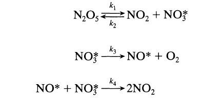
Show that the following schemeproposed by R. Ogg, J. Chem. Phys., 15,337 (1947) is consistent with, and can explain, the observed first-order decomposition of N205. k₁ N₂O5NO₂ + NO** k₂ NO NO* + NO k3 K4 NO* + 0₂ 2NO₂
The decomposition of reactant A at 400°C for pressures between 1 and 10 atm follows a first-order rate law.(a) Show that a mechanism similar to azomethane decomposition,is consistent with the observed kinetics.Different mechanisms can be proposed to explain first-order kinetics. To claim that this
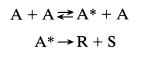
Experiment shows that the homogeneous decomposition of ozone proceeds with a rate(a) What is the overall order of reaction?(b) Suggest a two-step mechanism to explain this rate and state how you would further test this mechanism. -ro =k[0] [0]-
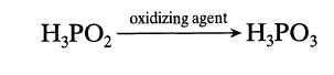
Under the influence of oxidizing agents, hypophosphorous acid is transformed into phosphorous acid: The kinetics of this transformation present the following features. At a low concentration of oxidizing agent,At a high concentration of oxidizing agent,To explain the observed kinetics, it has been
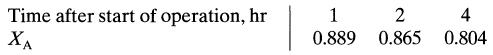
In an automobile's catalytic converter, CO and hydrocarbons present in the exhaust gases are oxidized. Unfortunately the effectiveness of these units decreases with use. The phenomenon was studied by Summers and Hegedus in J. Catalysis, 51, 185 (1978) by means of an accelerated aging test on a
The kinetics of a particular catalytic reaction A → R are studied at temperature T in a basket reactor (batch-solids and mixed flow of gas) in which the gas composition is kept unchanged, despite deactivation of the catalyst. What can you say about the rates of reaction and deactivation from the
The kinetics of a particular catalytic reaction A → R are studied at temperature T in a basket reactor (batch-solids and mixed flow of gas) in which the gas composition is kept unchanged, despite deactivation of the catalyst. What can you say about the rates of reaction and deactivation from the
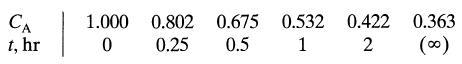
The following data on an irreversible reaction are obtained with decaying catalyst in a batch reactor (batch-solids, batch-fluid) What can you say about the kinetics CA t, hr 1 1.000 0 0.802 0.25 0.675 0.532 0.422 0.5 1 2 0.363 (00)
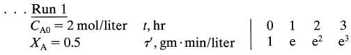
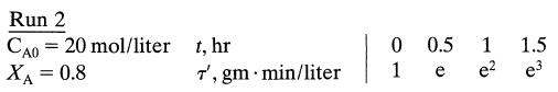
The reversible catalytic reactionproceeds with decaying catalyst in a batch reactor (batch-solids, batchfluid). What can you say of the kinetics of reaction and deactivation from the following data: AZR, XAe = 0.5
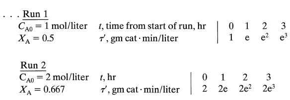
A recycle reactor with very high recycle ratio is used to study the kinetics of a particular irreversible catalytic reaction, A → R. For a constant flow rate of feed (τ' = 2 kg · sec/liter) the following data are obtained:The progressive drop in conversion suggests that the catalyst deactivates
With fresh catalyst the packed bed reactor is run at 600K. Four weeks later when the temperature reaches 800K the reactor is shut down to reactivate the catalyst. In addition, at any instant the reactor is isothermal. With fresh catalyst the packed bed reactor is run at 600K. Four weeks later when
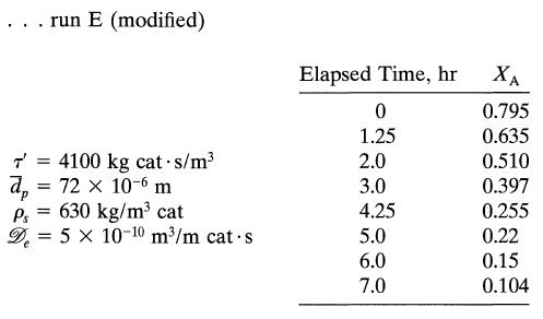
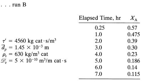
Our reaction A → R proceeds isothermally in a packed bed of large, slowly deactivating catalyst particles and is performing well in the strong pore diffusion regime. With fresh pellets conversion is 88%; however, after 250 days conversion drops to 64%. How long can we run the reactor before
It has been suggested that we replace these large particles with very small particles so as to operate wholly in the diffusion-free regime and thus use less catalyst for the same conversions. How long a run time can we expect before the conversion drops from 88% to 64% if the catalyst is used in. .
It has been suggested that we replace these large particles with very small particles so as to operate wholly in the diffusion-free regime and thus use less catalyst for the same conversions. How long a run time can we expect before the conversion drops from 88% to 64% if the catalyst is used in. .
Under conditions of strong pore diffusion the reaction A → R proceeds at 700°C on a slowly deactivating catalyst by a first-order rate Deactivation is caused by strong absorption of unavoidable and irremovable trace impurities in the feed, giving third-order deactivation kinetics, orWe plan to
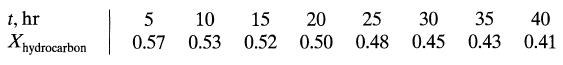
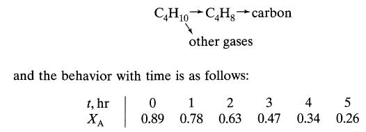
In catalytic dehydrogenation of hydrocarbons the catalyst activity decays with use because of carbon deposition on the active surfaces. Let us study this process in a specific system.A gaseous feed (10% C4, H10, - 90% inerts, π = 1 atm, T = 555°C) flows (τ' = 1.1 kg · hr/m3) through a packed
At 730K the isomerization of A to R (rearrangement of atoms in the molecule) proceeds on a slowly deactivating catalyst with a second-order rateSince reactant and product molecules are similar in structure, deactivation is caused by both A and R. With diffusional effects absent, the rate of
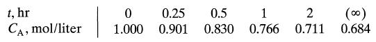
The enzyme catalase effectively decomposes hydrogen peroxideand the kinetics of this reaction are to be evaluated from an experiment in which dilute H202 flows through a packed bed of kieselguhr particles impregnated with immobilized enzyme. From the following data, reported by Krishnaswamy and
The enzyme catalase effectively decomposes hydrogen peroxideand the kinetics of this reaction are to be evaluated from an experiment in which dilute H202 flows through a packed bed of kieselguhr particles impregnated with immobilized enzyme. From the following data, reported by Krishnaswamy and
The batch hydrogenation takes just about an hour to run. Let us suppose that in practical operations we can run eight batches of fluid per day in this unit. Thus, in the long run a batch of fluid is processed every three hours. Another way of running this reaction is to feed the agitated reactor
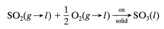
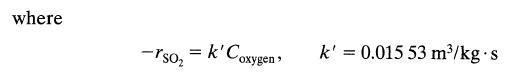
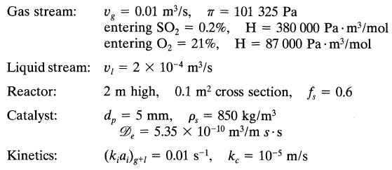
Sulfur dioxide is to be removed from a gas by passing the gas and water through a bed of highly porous activated carbon kept at 25°C. In this system sulfur dioxide and oxygen dissolve in water and react on the solid to give sulfur trioxide, as follows:Find the fraction of sulfur dioxide removed
Consider a different design to effect the hydrogenation of the previous problem, one which uses a long, narrow bubble column of semi suspended 3-mm catalyst particles (fs, = 0.4, fl = 0.5, fg = 0.1). The batch of liquid aniline is circulated through an external heat exchanger (volume of liquid in
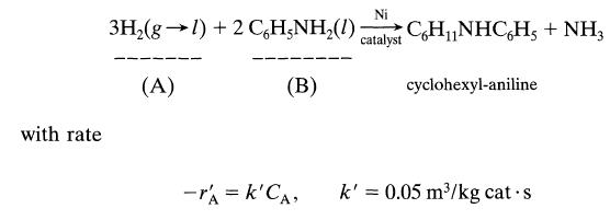
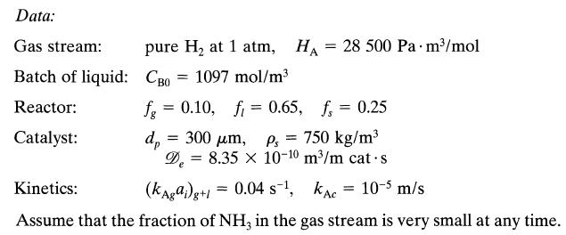
Aniline is to be hydrogenated in a three-phase fluidized bed of porous clay particles impregnated with nickel catalyst. The well-agitated batch of liquid is kept at 130°C by heat exchanger tubes passing through the fluidized bed, and by bubbling hydroAniline is to be hydrogenated in a three-phase
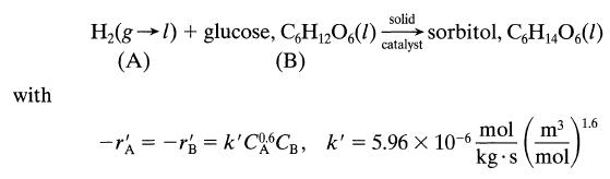
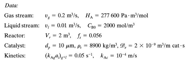
Predict the conversion of glucose to sorbitol in a stirred slurry reactor using pure hydrogen gas at 200 atm and 150°C. The catalyst used is porous Raney nickel, and under these conditions Brahme and Doraiswamy, IEC/PDD, 15,130 (1976) report that the reaction proceeds as follows:
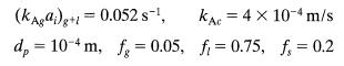
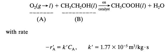
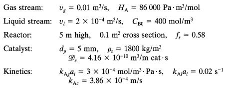
Instead of using a trickle bed reactor for ethanol oxidation (see previous problem), let us consider using a slurry reactor.For this type of unitTake all flows and other values from the previous problem, and then find the expected fractional conversion of ethanol in this reactor.Data from previous
Dilute aqueous ethanol (about 2-3%) is oxidized to acetic acid by the action of pure oxygen at 10 atm in a trickle bed reactor packed with palladium-alumina catalyst pellets and kept at 30°C. According to Sato et al., Proc. First Pacific Chem. Eng. Congress, Kyoto, p. 197,1972, the reaction
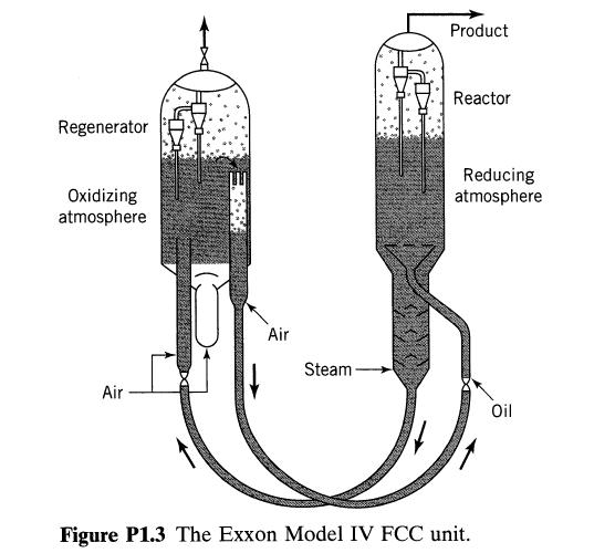
FCC reactors are among the largest processing units used in the petroleum industry. Figure P1.3 shows an example of such units. A typical unit is 4-10 m ID and 10-20 m high and contains about 50 tons of p = 800 kg/m3 porous catalyst. It is fed about 38 000 barrels of crude oil per day (6000 m3/day
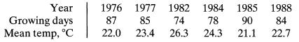
Every May 22 I plant one watermelon seed. I water it, I fight slugs, I pray, I watch my beauty grow, and finally the day comes when the melon ripens. I then harvest and feast. Of course, some years are sad, like 1980, when a bluejay flew off with the seed. Anyway, six summers were a pure joy and
The maximum allowable temperature for a reactor is 800 K. At present our operating set point is 780 K, the 20-K margin of safety to account for fluctuating feed, sluggish controls, etc. Now, with a more sophisticated control system we would be able to raise our set point to 792 K with the same
The pyrolysis of ethane proceeds with an activation energy of about 300 kJ/mol. How much faster is the decomposition at 650°C than at 500°C?
A 1100-K n-nonane thermally cracks (breaks down into smaller molecules) 20 times as rapidly as at 1000 K. Find the activation energy for this decomposition.
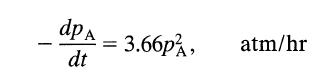
For a gas reaction at 400 K the rate is reported as(a) What are the units of the rate constant?(b) What is the value of the rate constant for this reaction if the rate equation is expressed as dp A dt 3.66p, atm/hr
The decomposition of nitrous oxide is found to proceed as follows:What is the order of this reaction with respect to N,O, and overall? +21/20₂₂ N₂O →N₂ + k₁[N₂O]² -N₂0 = 1+ k₂[N₂O]
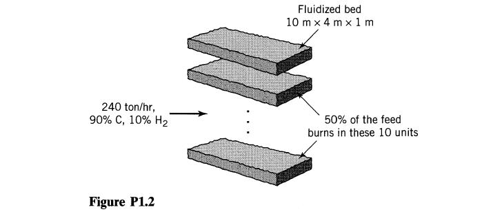
Large central power stations (about 1000 MW electrical) using fluidized bed combustors may be built some day (see Fig. P1.2). These giants would be fed 240 tons of coal/hr (90% C, 10% H,), 50% of which would burn within the battery of primary fluidized beds, the other 50% elsewhere in the
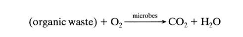
Consider a municipal water treatment plant for a small community (Fig. P1.1). Waste water, 32,000 m3/day, flows through the treatment plant with a mean residence time of 8 hr, air is bubbled through the tanks, and microbes in the tank attack and break down the organic materialtypical entering feed
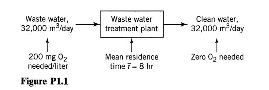
For a given feed stream having C,, should we use a PFR or a MFR and should we use a high or low or some intermediate conversion level for the exit stream if we wish to maximize (p(SIA)? The reaction system iswhere n,, n,, and n, are the reaction orders of reactions 1, 2, and 3.(a) n1 = 1, n2 = 2,
Using separate feeds of A and B sketch the contacting pattern and reactor conditions which would best promote the formation of product R for the following systems of elementary reactions A+B R S. A Flow system
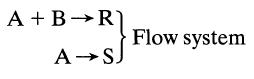
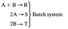
Using separate feeds of A and B sketch the contacting pattern and reactor conditions which would best promote the formation of product R for the following systems of elementary reactions A+B R S Batch system 2A 2B → T
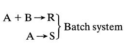
Using separate feeds of A and B sketch the contacting pattern and reactor conditions which would best promote the formation of product R for the following systems of elementary reactions A + B →R A → SJ Batch system
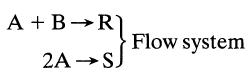
Using separate feeds of A and B sketch the contacting pattern and reactor conditions which would best promote the formation of product R for the following systems of elementary reactions A + B →R 2A → SJ Flow system
Substance A in the liquid phase produces R and S by the following reactions:The feed (CAo = 1.0, CRo = 0, Cso = 0.3) enters two mixed flow reactors in series (τ1 = 2.5 min, τ2, = 10 min). Knowing the composition in the first reactor (CAI = 0.4, CRl = 0.2, CS1 = 0.7), find the composition leaving
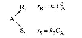
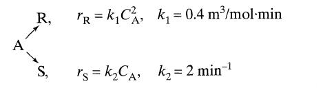
Find CR, and CS, and τ for XA, = 0.9 in a mixed flow reactor.Liquid reactant A decomposes as follows:A feed of aqueous A (CA0 = 40 mol/m3) enters a reactor, decomposes, and a mixture of A, R, and S leaves. A R, S, TR = k₁C₁, k₁= 0.4 m³/mol-min rs=k₂CA, K₂=2 min-¹
Find CR, and Cs and τ for X, = 0.9 in a mixed flow reactor.Liquid reactant A decomposes as follows:A feed of aqueous A (CA0 = 40 mol/m3) enters a reactor, decomposes, and a mixture of A, R, and S leaves. A R, S, TR = k₁C₁, k₁ = 0.4 m³/mol-min rs=k₂CA, K₂= 2 min-¹
Find the operating condition (XA, τ, and CR) which maximizes CR in a mixed flow reactor.Liquid reactant A decomposes as follows:A feed of aqueous A (CA0 = 40 mol/m3) enters a reactor, decomposes, and a mixture of A, R, and S leaves. A R, S, TR = k₁C₁, k₁= 0.4 m³/mol-min rs=k₂CA, K₂= 2
Find the operating condition (XA, τ, and CS) which maximizes Cs in a mixed flow reactor.Liquid reactant A decomposes as follows:A feed of aqueous A (CA0 = 40 mol/m3) enters a reactor, decomposes, and a mixture of A, R, and S leaves. A R, S, TR = k₁C₁, k₁= 0.4 m³/mol-min rs=k₂CA, K₂=2
Reactant A in a liquid either isomerizes or dimerizes as follows:(a) Write φ(R/A) and φ([RI(R + S)]. With a feed stream of concentration CA0 find CR,max which can be formed(b) In a plug flow reactor,(c) In a mixed flow reactor.A quantity of A of initial concentration CA0 = 1 mol/liter is dumped
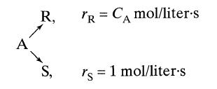
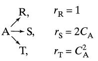
In a reactive environment, chemical A decomposes as followsFor a feed stream CA0 = 4 mol/ter what size ratio of two mixed flow reactors will maximize the production rate of R? Also give the composition of A and R leaving these two reactors. A R, S, TR = CA mol/liter-s rs 1 mol/liter.s
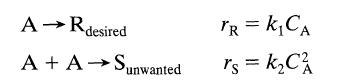
Consider the parallel decomposition of A of different orders.Determine the maximum concentration of desired product obtainable in(a) Plug flow,(b) Mixed flow.R is the desired product and CAo = 2. R, A-S, А T, TR = 1 rs = 2CA rT=C² A
Consider the parallel decomposition of A of different orders.Determine the maximum concentration of desired product obtainable in(a) Plug flow,(b) Mixed flow.S is the desired product and CAo = 4. R, A-S, А T, TR = 1 rs = 2CA rT=C² A
Consider the parallel decomposition of A of different orders.Determine the maximum concentration of desired product obtainable in(a) Plug flow,(b) Mixed flow.T is the desired product and CA0 = 5. R, A-S, А T, TR = 1 rs = 2CA rT=C² A
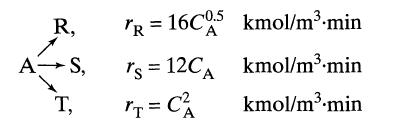
How should we operate a mixed flow reactor so as to maximize the production of R? Separation and recycle of unused reactant is not practical.Under ultraviolet radiation, reactant A of CA0 = 10 kmol/m3 in a process stream (v = lm3/min) decomposes as follows.We wish to design a reactor setup for a
How should we operate a mixed flow reactor so as to maximize the production of R? Separation and recycle of unused reactant is not practical.When aqueous A and aqueous B (CA0 = CB0) are brought together they react in two possible ways:to give a mixture whose concentration of active components (A,
How should we operate a mixed flow reactor so as to maximize the production of R? Separation and recycle of unused reactant is not practical.When aqueous A and aqueous B (CA0 = CB0) are brought together they react in two possible ways:to give a mixture whose concentration of active components (A,
How should we operate a mixed flow reactor so as to maximize the production of R? Separation and recycle of unused reactant is not practical.When aqueous A and aqueous B (CA0 = CB0) are brought together they react in two possible ways:to give a mixture whose concentration of active components (A,
Reactant A decomposes in an isothermal batch reactor (CA0 = 100) to produce wanted R and unwanted S, and the following progressive concentration readings are recorded:Additional runs show that adding R or S does not affect the distribution of products formed and that only A does. Also, it is noted
Examples 9.4 through 9.7 illustrate the approach to problems dealing with non isothermal reactors. This approach to multistage operations of solid catalyzed reactions.To reinforce these concepts, Problems 9.1 through 9.9 ask the reader to redo these examples with one or more changes. In many of
Examples 9.4 through 9.7 illustrate the approach to problems dealing with non isothermal reactors. This approach to multistage operations of solid catalyzed reactions.To reinforce these concepts, Problems 9.1 through 9.9 ask the reader to redo these examples with one or more changes. In many of
Examples 9.4 through 9.7 illustrate the approach to problems dealing with non isothermal reactors. This approach to multistage operations of solid catalyzed reactions.To reinforce these concepts, Problems 9.1 through 9.9 ask the reader to redo these examples with one or more changes. In many of
Examples 9.4 through 9.7 illustrate the approach to problems dealing with non isothermal reactors. This approach to multistage operations of solid catalyzed reactions.To reinforce these concepts, Problems 9.1 through 9.9 ask the reader to redo these examples with one or more changes. In many of
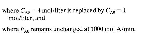
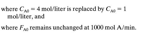
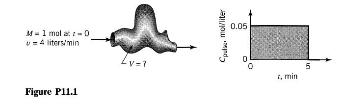
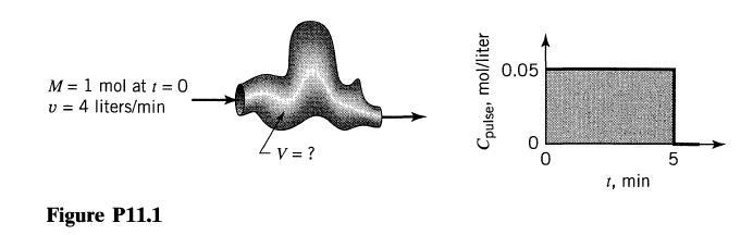
A pulse input to a vessel gives the results shown in Fig. P11.1.(a) Check the material balance with the tracer curve to see whether the results are consistent.(b) If the result is consistent, determine t̅, V and sketch the E curve. M = 1 mol at t = 0 v = 4 liters/min Figure P11.1 V = ? Cpulse,
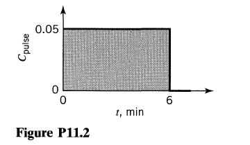
Repeat Problem P11.1 with one change: The tracer curve is now as shown in Fig. P11.2. Cpuise 0.05 0 0 Figure P11.2 t, min 6
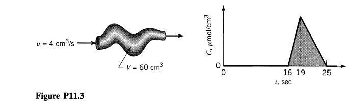
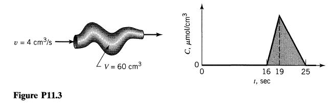
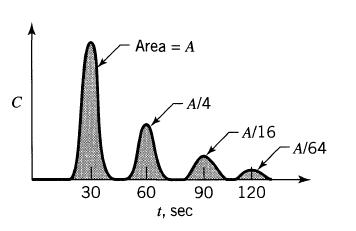
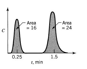
A pulse input to a vessel gives the results shown in Fig. P11.3.(a) Are the results consistent? (Check the material balance with the experimental tracer curve.)(b) If the results are consistent, determine the amount of tracer introduced M, and the E curve. v = 4 cm³/s Figure P11.3 V = 60 cm³ C,
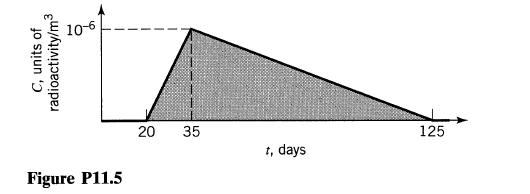
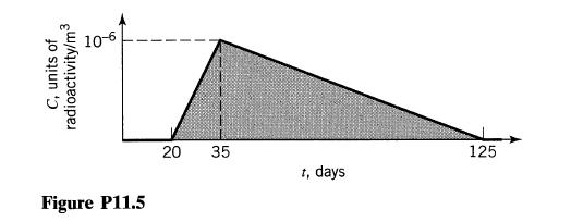
A batch of radioactive material is dumped into the Columbia River at Hanford, Washington. At Bonneville Dam, about 400 km downstream the flowing waters (6000 m3/s) are monitored for a particular radioisotope (t1/2 > 10 yr) and the data of Fig. P11.5 are obtained.(a) How many units of this tracer
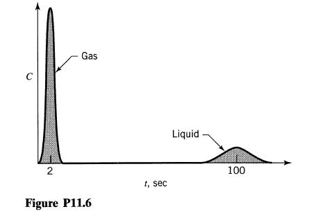
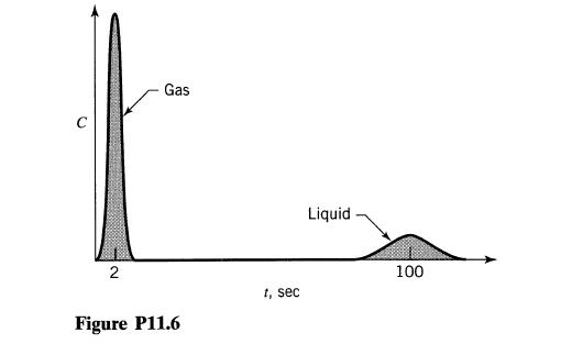
A pipeline (10 cm I.D., 19.1 m long) simultaneously transports gas and liquid from here to there. The volumetric flow rate of gas and liquid are 60 000 cm3/s and 300 cm3/s, respectively. Pulse tracer tests on the fluids flowing through the pipe give results as shown in Fig. P11.6. What fraction of
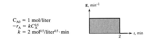
A liquid macrofluid reacts according to A → R as it flows through a vessel. Find the conversion of A for the flow patterns CAO -TA = KC05 k = 2 mol 0.5/liter0.5. min 1 mol/liter E, min-¹ 2 t, min
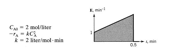
A liquid macrofluid reacts according to A → R as it flows through a vessel. Find the conversion of A for the flow patterns CAO 2 mol/liter = -TA = KC² k = 2 liter/mol. min E, min-1 1 0.5 t, min
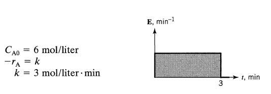
A liquid macrofluid reacts according to A → R as it flows through a vessel. Find the conversion of A for the flow patterns CAO 6 mol/liter = -TA = k k = 3 mol/liter.min E, min-1 3 t, min
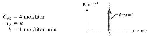
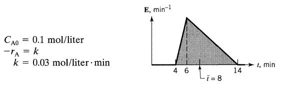
A liquid macrofluid reacts according to A → R as it flows through a vessel. Find the conversion of A for the flow patterns CA04 mol/liter -TA = k k = 1 mol/liter min E, min-1 3 Area = 1 1, min
A liquid macrofluid reacts according to A → R as it flows through a vessel. Find the conversion of A for the flow patterns
Examples 9.4 through 9.7 illustrate the approach to problems dealing with non isothermal reactors. This approach to multistage operations of solid catalyzed reactions.To reinforce these concepts, Problems 9.1 through 9.9 ask the reader to redo these examples with one or more changes. In many of
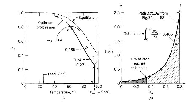
For the reaction system of Example 9.4(a) Find needed for 60% conversion of reactant using the optimal temperature progression in the plug flow reactor.(b) Also find the exit temperature of fluid from the reaction.Example 9.4Using the optimal temperature progression in a plug flow reactor for the
For the optimum temperature progression in a plug flow reactor in Example 9.4 (CA0 = 4 mol/liter, FA0 = 1000 mol A/min, XA0 = 0.8, T = 5°C, Tmax = 95°C) and feed and product both at 25°C, how much heating and cooling would be needed.(a) For the feed stream?(b) In the reactor itself?(c) For the
A pulse input to a vessel gives the results shown in Fig. P11.1.(a) Check the material balance with the tracer curve to see whether the results are consistent.(b) If the result is consistent, determine t, V and sketch the E curve. M = 1 mol at t = 0 v = 4 liters/min Figure P11.1 - V = ? Cpulse,
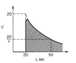
A pulse input to a vessel gives the results shown in Fig. P11.3.(a) Are the results consistent?(b) If the results are consistent, determine the amount of tracer introduced M, and the E curve. v = 4 cm³/s Figure P11.3 V = 60 cm³ C, μmol/cm³ 16 19 1, sec 25
A batch of radioactive material is dumped into the Columbia River at Hanford, Washington. At Bonneville Dam, about 400 km downstream the flowing waters (6000 m3/s) are monitored for a particular radioisotope (t1/2> 10 yr) and the data of Fig. P11.5 are obtained.(a) How many units of this tracer
A pipeline (10 cm I.D., 19.1 m long) simultaneously transports gas and liquid from here to there. The volumetric flow rate of gas and liquid are 60,000 cm3/s and 300 cm3/s, respectively. Pulse tracer tests on the fluids flowing through the pipe give results as shown in Fig. P11.6. What fraction of
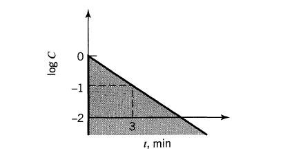
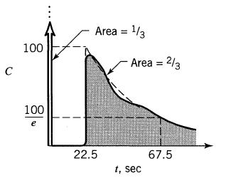
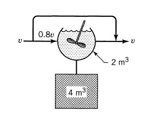
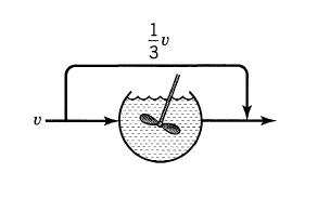
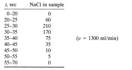
A pulse of concentrated NaCl solution is introduced as tracer into the fluid entering a vessel (V = 1 m3, v = 1 m3/min) and the concentration of tracer is measured in the fluid leaving the vessel. Develop a flow model to represent the vessel from the tracer output data sketched in Figs. P12.1 to
A pulse of concentrated NaCl solution is introduced as tracer into the fluid entering a vessel (V = 1 m3, v = 1 m3/min) and the concentration of tracer is measured in the fluid leaving the vessel. Develop a flow model to represent the vessel from the tracer output data sketched in Figure. Area =
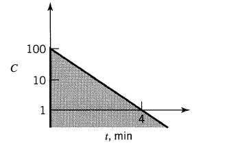
A pulse of concentrated NaCl solution is introduced as tracer into the fluid entering a vessel (V = 1 m3, v = 1 m3/min) and the concentration of tracer is measured in the fluid leaving the vessel. Develop a flow model to represent the vessel from the tracer output data sketched in Figs. P12.1 to
A pulse of concentrated NaCl solution is introduced as tracer into the fluid entering a vessel (V = 1 m3, v = 1 m3/min) and the concentration of tracer is measured in the fluid leaving the vessel. Develop a flow model to represent the vessel from the tracer output data sketched in Figs. P12.1 to
A pulse of concentrated NaCl solution is introduced as tracer into the fluid entering a vessel (V = 1 m3, v = 1 m3/min) and the concentration of tracer is measured in the fluid leaving the vessel. Develop a flow model to represent the vessel from the tracer output data sketched in Figs. P12.1 to
A pulse of concentrated NaCl solution is introduced as tracer into the fluid entering a vessel (V = 1 m3, v = 1 m3/min) and the concentration of tracer is measured in the fluid leaving the vessel. Develop a flow model to represent the vessel from the tracer output data sketched in Figs. P12.1 to
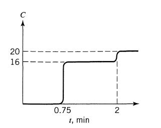
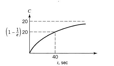
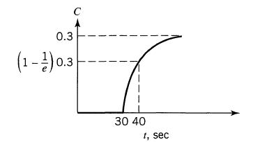
A step input tracer test (switching from tap water to salt water, measuring the conductivity of fluid leaving the vessel) is used to explore the flow pattern of fluid through the vessel (V = 1 m3, v = 1 m3/min). Devise a flow model to represent the vessel from the data of Figs. P12.7 to P12.10.
A step input tracer test (switching from tap water to salt water, measuring the conductivity of fluid leaving the vessel) is used to explore the flow pattern of fluid through the vessel (V = 1 m3, v = 1 m3/min). Devise a flow model to represent the vessel from the data of Figs. P12.7 to P12.10.
A step input tracer test (switching from tap water to salt water, measuring the conductivity of fluid leaving the vessel) is used to explore the flow pattern of fluid through the vessel (V = 1 m3, v = 1 m3/min). Devise a flow model to represent the vessel from the data of Figs. P12.7 to P12.10.
The second order aqueous reaction A + B→R + S is run in a large tank reactor (V = 6 m3) and for an equimolar feed stream (CA0=CB0) conversion of reactants is 60%. Unfortunately, agitation in our reactor is rather inadequate and tracer tests of the flow within the reactor give the flow model
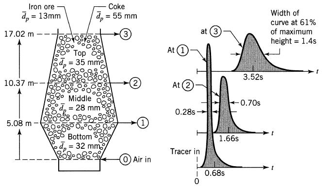
The flow pattern of gas through blast furnaces was studied by VDEh (Veren Deutscher Eisenhiittenleute Betriebsforschungsinstitut) by injecting Kr-85 into the air stream entering the tuyeres of the 688 m3 furnace. A sketch and listing of pertinent quantities for run 10.5 of 9.12.1969 is shown in
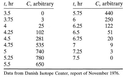
Denmark's longest and greatest river, the Gudenaa, certainly deserves study, so pulse tracer tests were run on various stretches of the river using radioactive Br-82. Find the axial dispersion coefficient in the upper stretch of the river, between Torring and Udlum, 8.7 km apart, from the following
The second order aqueous reaction A + B → R + S is run in a large tank reactor (V = 6 m3) and for an equimolar feed stream (CA0=CB0) conversion of reactants is 60%. Unfortunately, agitation in our reactor is rather inadequate and tracer tests of the flow within the reactor give the flow model
RTD studies were carried out by Jagadeesh and Satyanarayana (IECIPDD = 11 520, 1972) in a tubular reactor (L = 1.21 m, 35 mm ID). A squirt of NaCl solution (5 N) was rapidly injected at the reactor entrance, and mixing cup measurements were taken at the exit. From the following results calculate
Water is drawn from a lake, flows through a pump and passes down a long pipe in turbulent flow. A slug of tracer (not an ideal pulse input) enters the intake line at the lake, and is recorded downstream at two locations in the pipe L meters apart. The mean residence time of fluid between recording
Kerosene and gasoline are pumped successively at 1.1 m/s through a 25.5cm ID pipeline 1000 km long. Calculate the 5195%-9515% contaminated width at the exit of the pipe given that the kinematic viscosity for the 501 50% mixture is:(Data and problem from Sjenitzer, Pipeline Engineer, December 1958).
Showing 600 - 700
of 748
1
2
3
4
5
6
7
8
Step by Step Answers
![A+E=X k XR+E with K = [X] [A][E]' and with [E] [E] + [X]](https://dsd5zvtm8ll6.cloudfront.net/si.question.images/images/question_images/1695/9/1/3/459651595f306d8a1695913456524.jpg)
![k A+EX k k3 X-KR+E with d[X] dt = 0, and [E] [E] + [X] =](https://dsd5zvtm8ll6.cloudfront.net/si.question.images/images/question_images/1695/9/1/3/4856515960d79c101695913483256.jpg)
![-ro =k[0] [0]-](https://dsd5zvtm8ll6.cloudfront.net/si.question.images/images/question_images/1696/7/5/5/40165226ec990a421696755401159.jpg)
![HPO = k[H+][HPO]](https://dsd5zvtm8ll6.cloudfront.net/si.question.images/images/question_images/1696/0/5/7/9856517ca81bf6451696057983265.jpg)
![da dt == Ka(CA+CR) a = 10(CA + CR)a, [day-]](https://dsd5zvtm8ll6.cloudfront.net/si.question.images/images/question_images/1696/6/7/4/88565213445684ca1696674880900.jpg)
![+21/20 N,ON,+ k[NO] -N01+ k[NO]](https://dsd5zvtm8ll6.cloudfront.net/si.question.images/images/question_images/1695/9/0/9/080651584d8b7d351695909078860.jpg)