New Semester
Started
Get
50% OFF
Study Help!
--h --m --s
Claim Now
Question Answers
Textbooks
Find textbooks, questions and answers
Oops, something went wrong!
Change your search query and then try again
S
Books
FREE
Study Help
Expert Questions
Accounting
General Management
Mathematics
Finance
Organizational Behaviour
Law
Physics
Operating System
Management Leadership
Sociology
Programming
Marketing
Database
Computer Network
Economics
Textbooks Solutions
Accounting
Managerial Accounting
Management Leadership
Cost Accounting
Statistics
Business Law
Corporate Finance
Finance
Economics
Auditing
Tutors
Online Tutors
Find a Tutor
Hire a Tutor
Become a Tutor
AI Tutor
AI Study Planner
NEW
Sell Books
Search
Search
Sign In
Register
study help
engineering
mechanical engineering
Fundamentals of Heat and Mass Transfer 6th Edition Incropera, Dewitt, Bergman, Lavine - Solutions
The fin array of Problem 3.130 is commonly found in compact heat exchangers, whose function is to provide a large surface area per unit volume in transferring heat from one fluid to another. Consider conditions for which the second fluid maintains equivalent temperatures at the parallel plates, To
An isothermal silicon chip of width W = 20 mm on a side is soldered to an aluminum heat sink (k = 180 W/m ∙ K) of equivalent width. The heat sink has a base thickness of Lb = 3 mm and an array of rectangular fins, each of length Lf = 15 mm. Air flow at T∞ = 20°C is maintained through
As seen in Problem 3.109, silicon carbide nanowires of diameter D = 15 nm can be grown onto a solid silicon carbide surface by carefully depositing droplets of catalyst liquid onto a flat silicon carbide substrate. Silicon carbide nanowires grow upward from the deposited drops, and if the drops are
As more and more components are placed on a single integrated circuit (chip), the amount of heat that is dissipated continues to increase. However, this increase is limited by the maximum allowable chip operating temperature, which is approximately 75°C. To maximize heat dissipation, it is
In Problem 3.134, the prescribed value of ho = 1000 W/m2 ∙ K is large and characteristic of liquid cooling. In practice it would be far more preferable to use air cooling, for which a reasonable upper limit to the convection coefficient would be ho = 250 W/m2 ∙ K. Assess the effect of changes
As a means of enhancing heat transfer from high-performance logic chips, it is common to attach a heat sink to the chip surface in order to increase the surface area available for convection heat transfer. Because of the ease with which it may be manufactured (by taking orthogonal saw cuts in a
Because of the large number of devices in today's PC chips, finned heat sinks are often used to maintain the chip at an acceptable operating temperature. Two fin designs are to be evaluated, both of which have base (unfinned) area dimensions of 53 mm X 57 mm. The fins are of square cross section
Consider design B of Problem 3.137. Over time, dust can collect in the fine grooves that separate the fins. Consider the buildup of a dust layer of thickness Ld, as shown in the sketch. Calculate and plot the total heat rate for design B for dust layers in the range 0
A long rod of 20-mm diameter and a thermal conductivity of 1.5 W/m ∙ K has a uniform internal volumetric thermal energy generation of 10 6 W/m3. The rod is covered with an electrically insulating sleeve of 2-mm thickness and thermal conductivity of 0.5 W/m ∙ K. A spider with 12 ribs and
An air heater consists of a steel tube (k = 20 W/m ∙ K), with inner and outer radii of r( = 13 mm and r2 = 16 mm, respectively, and eight integrally machined longitudinal fins, each of thickness t = 3 mm. The fins extend to a concentric tube, which is of radius r3 = 40 mm and insulated on its
Determine the percentage increase in heat transfer associated with attaching aluminum fins of rectangular profile to a plane wall. The fins are 50 mm long, 0.5 mm thick, and are equally spaced at a distance of 4 mm (250fins/m). The convection coefficient associated with the bare wall is 40 W/m2 ∙
Heat is uniformly generated at the rate of 2 x 10⁵ W/m 3 in a wall of thermal conductivity 25 W/m ∙ K and thickness 60 mm. The wall is exposed to convection on both sides, with different heat transfer coefficients and temperatures as shown. There are straight rectangular fins on the right-hand
Aluminum fins of triangular profile are attached to a plane wall whose surface temperature is 250°C. The fin base thickness is 2 mm, and its length is 6 mm. The system is in ambient air at a temperature of 20°C, and the surface convection coefficient is 40 W/m2 ∙ K.(a) What are the fin
An annular aluminum fin of rectangular profile is attached to a circular tube having an outside diameter of 25 mm and a surface temperature of 250°C. The fin is 1 mm thick and 10 mm long, and the temperature and the convection coefficient associated with the adjoining fluid are 25°C and 25 W/m2
Annular aluminum fins of rectangular profile are attached to a circular tube having an outside diameter of 50 mm and an outer surface temperature of 200°C. The fins are 4 mm thick and 15 mm long. The system is in ambient air at a temperature of 20°C, and the surface convection coefficient is 40
It is proposed to air-cool the cylinders of a combustion chamber by joining an aluminum casing with annular fins (k = 240 W/m ∙ K) to the cylinder wall (k = 50 W/m ∙ K).The air is at 320K and the corresponding convection coefficient is 100 W/m2 ∙ K. Although heating at the inner surface is
Consider the air-cooled combustion cylinder of Problem 3.146, but instead of imposing a uniform heat flux at the inner surface, consider conditions for which the time-averaged temperature of the combustion gases is Tg = 1100 K and the corresponding convection coefficient is hg = 150 W/m2 ∙ K. All
Water is heated by submerging 50-mm diameter, thin-walled copper tubes in a tank and passing hot combustion gases (Tg = 750 K) through the tubes. To enhance heat transfer to the water, four straight fins of uniform cross section, which form a cross, are inserted in each tube. The fins are 5 mm
Consider the conditions of Problem 3.149, but now allow for a tube wall thickness of 5 mm (inner and outer diameters of 50 and 60 mm), a fin-to-tube thermal contact resistance of 10- 4 m2 ∙ K/W, and the fact that it is the water temperature, T w = 350 K, rather than the tube surface temperature,
A scheme for concurrently heating separate water and air streams involves passing them through and over an array of tubes, respectively, while the tube wall is heated electrically. To enhance gas-side heat transfer, annular fins of rectangular profile are attached to the outer tube surface.
Consider the conditions of Example 3.12, except that the person is now exercising (in the air environment), which increases the metabolic heat generation rate by a factor of eight, to 5600 W/m3. At what rate would the person have to perspire (in liters/s) to maintain the same skin temperature as in
In the method of separation of variables (Section 4.2) for two-dimensional, steady-state conduction, the separation constant λ2 in Equations 4.6 and 4.7 must be a positive constant. Show that a negative or zero value of A 2 will result in solutions that cannot satisfy the prescribed boundary
A two-dimensional rectangular plate is subjected to prescribed boundary conditions. Using the results of the exact solution for the heat equation presented in Section 4.2, calculate the temperature at the midpoint (1, 0.5) by considering the first five nonzero terms of the infinite series that must
Consider the two-dimensional rectangular plate of Problem 4.2 having a thermal conductivity of 50 W/m ∙ K. Beginning with the exact solution for the temperature distribution derive an expression for the heat transfer rate per unit thickness from the plate along the lower surface (0 < x < 2,
A two-dimensional rectangular plate is subjected to the boundary conditions shown. Derive an expression for the steady-state temperature distribution T(x, y).
A two-dimensional rectangular plate is subjected to prescribed temperature boundary conditions on three sides and a uniform heat flux into the plate at the top surface. Using the general approach of Section 4.2, derive an expression for the temperature distribution in the plate.
Using the thermal resistance relations developed in Chapter 3, determine shape factor expressions for the following geometries:(a) Plane wall, cylindrical shell, and spherical shell.(b) Isothermal sphere of diameter D buried in an infinite medium.
Consider Problem 4.5 for the case where the plate is of square cross section, W = L.(a) Derive an expression for the shape factor, Smax associated with the maximum top surface temperature, such that q = Smax k (T2,max – T1) where T2.max is the maximum temperature along y = W.(b) Derive an
Based on the dimensionless conduction heat rates for cases 12-15 in Table 4.1 b, find shape factors for the following objects having temperature T1, located at the surface of a semi-infinite medium having temperature T2 the surface of the semi-infinite medium is adiabatic.(a) A buried hemisphere,
Radioactive wastes are temporarily stored in a spherical container, the center of which is buried a distance of 10 m below the earth's surface. The outside diameter of the container is 2 m, and 500 W of heat are released as a result of the radioactive decay process. If the soil surface temperature
A pipeline, used for the transport of crude oil, is buried in the earth such that its centerline is a distance of 1.5 m below the surface. The pipe has an outer diameter of 0.5 m and is insulated with a layer of cellular glass 100 mm thick. What is the heat loss per unit length of pipe under
A long power transmission cable is buried at a depth (ground to cable centerline distance) of 2 m. The cable is encased in a thin-walled pipe of 0.1-m diameter, and to render the cable superconducting (essentially zero power dissipation), the space between the cable and pipe is filled with liquid
An electrical heater 100 mm long and 5 mm in diameter is inserted into a hole drilled normal to the surface of a large block of material having a thermal conductivity of 5 W/m ∙ K. Estimate the temperature reached by the heater when dissipating 50 W with the surface of the block at a temperature
Two parallel pipelines spaced 0.5 m apart are buried in soil having a thermal conductivity of 0.5 W/m ∙ K. The pipes have outer diameters of 100 and 75 mm with surface temperatures of 175°C and 5°C, respectively. Estimate the heat transfer rate per unit length between the two pipelines.
A tube of diameter 50 mm having a surface temperature of 85°C is embedded in the center plane of a concrete slab 0.1 m thick with upper and lower surfaces at 20°C. Using the appropriate tabulated relation for this configuration, find the shape factor. Determine the heat transfer rate per unit
Pressurized steam at 450 K flows through a long, thin-walled pipe of 0.5-m diameter. The pipe is enclosed in a concrete casing that is of square cross section and 1.5 m on a side. The axis of the pipe is centered in the casing, and the outer surfaces of the casing are maintained at 300 K. What is
Hot water at 85°C flows through a thin-walled copper tube of 30 mm diameter. The tube is enclosed by an eccentric cylindrical shell that is maintained at 35°C and has a diameter of 120 mm. The eccentricity, defined as the separation between the centers of the tube and shell, is 20 mm. The space
A furnace of cubical shape, with external dimensions of 0.35 m, is constructed from a refractory brick (fireclay). If the wall thickness is 50 mm, the inner surface temperature is 600°C, and the outer surface temperature is 75°C, calculate the heat loss from the furnace.
The temperature distribution in laser-irradiated materials is determined by the power, size, and shape of the laser beam, along with the properties of the material being irradiated. The beam shape is typically Gaussian, and the local beam irradiation flux (often referred to as the laser flounce) is
Laser beams are used to thermally process materials in a wide range of applications. Often, the beam is scanned along the surface of the material in a desired pattern. Consider the laser heating process of Problem 4.18, except now the laser beam scans the material at a scanning velocity of U. A
A cubical glass melting furnace has exterior dimensions of width W = 5 m on a side and is constructed from refractory brick of thickness L = 0.35 m and thermal conductivity k = 1.4 W/m. K. The sides and top of the furnace are exposed to ambient air at 25°C, with free convection characterized by an
A hot fluid passes through circular channels of a cast iron platen (A) of thickness LA = 30 mm which is in poor contact with the cover plates (B) of thickness L B = 7.5 mm. The channels are of diameter D = 15 mm with a centerline spacing of La = 60 mm. The thermal conductivities of the materials
A long constantan wire of 1-mm diameter is butt welded to the surface of a large copper block, forming a thermo-couple junction. The wire behaves as a fin, permitting heat to flow from the surface, thereby depressing the sensing junction temperature Tj below that of the block To.(a) If the wire is
A hole of diameter D = 0.25 m is drilled through the center of a solid block of square cross section with w = 1m on a side. The hole is drilled along the length, 1 = 2 m, of the block, which has a thermal conductivity of k = 150 W/m ∙ K. The outer surfaces are exposed to ambient air, with T∞,2
In Chapter 3 we assumed that, whenever fins are attached to a base material, the base temperature is unchanged. What in fact happens is that, if the temperature of the base material exceeds the fluid temperature, attachment of a fin depresses the junction temperature below the original temperature
An igloo is built in the shape of a hemisphere, with an inner radius of 1.8 m and walls of compacted snow that are 0.5 m thick. On the inside of the igloo the surface heat transfer coefficient is 6 W/m 2 ∙ K on the outside, under normal wind conditions, it is 15 W/m2 ∙ K. The thermal
Consider the thin integrated circuit (chip) of Problem 3.136. Instead of attaching the heat sink to the chip surface, an engineer suggests that sufficient cooling might be achieved by mounting the top of the chip onto a large copper (k = 400 W/m ∙ K) surface that is located nearby. The
An electronic device, in the form of a disk 20 mm in diameter, dissipates 100 W when mounted flush on a large aluminum alloy (2024) block whose temperature is maintained at 27°C. The mounting arrangement is such that a contact resistance of Rt,c = 5 X 10⁻⁵ m2 ∙ K/W exists at the interface
An aluminum heat sink (k = 240 W/m ∙ K) used to cool an array of electronic chips consists of a square channel of inner width w = 25 mm, through which liquid flow may be assumed to maintain a uniform surface temperature of T1 = 20°C. The outer width and length of the channel are W = 40 mm and
Hot water is transported from a cogeneration power station to commercial and industrial users through steel pipes of diameter D = 150 mm, with each pipe centered in concrete (k = 1.4 W/m ∙ K) of square cross section (w = 300 mm). The outer surfaces of the concrete are exposed to ambient air for
The elemental unit of an air heater consists of a long circular rod of diameter D, which is encapsulated by a finned sleeve and in which thermal energy is generated by Ohmic heating. The N fins of thickness t and length L are integrally fabricated with the square sleeve of width w. Under
For a small heat source attached to a large substrate, the spreading resistance associated with multidimensional conduction in the substrate may be approximated by the expression where Ar = As,h/As.sub is the ratio of the heat source area to the substrate area. Consider application of the
Consider nodal configuration 2 of Table 4.2. Derive the finite-difference equations under steady-state conditions for the following situations.(a) The horizontal boundary of the internal comer is perfectly insulated and the vertical boundary is subjected to the convection process (T∞, h).(b) Both
Consider nodal configuration 3 of Table 4.2. Derive the finite-difference equations under steady-state conditions for the following situations.(a) The boundary is insulated. Explain how Equation 4.42 can be modified to agree with your result.(b) The boundary is subjected to a constant heat flux.
Consider nodal configuration 4 of Table 4.2. Derive the finite-difference equations under steady-state conditions for the following situations. (a) The upper boundary of the external corner is perfectly insulated and the side boundary is subjected to the convection process (T∞, h). (b) Both
One of the strengths of numerical methods is their ability to handle complex boundary conditions. In the sketch, the boundary condition changes from specified heat flux, if: (into the domain), to convection, at the location of the node m, n. Write the steady-state, two-dimensional finite difference
Consider heat transfer in a one-dimensional (radial) cylindrical coordinate system under steady-state conditions with volumetric heat generation.(a) Derive the finite-difference equation for any interior node m.(b) Derive the finite-difference equation for the node n located at the external
In a two-dimensional cylindrical configuration the radial (∆r) and angular (∆∅) spacing's of the nodes are uniform. The boundary at r = ri is of uniform temperature Ti. The boundaries in the radial direction are adiabatic (insulated) and exposed to surface convection (T∞, h), as
Upper and lower surfaces of a bus bar are convectively cooled by air at T∞ with hu ≠ h1. The sides are cooled by maintaining contact with heat sinks at To, through a thermal contact resistance of Rt,c The bar is of thermal conductivity k, and its width is twice its thickness L.Consider
Derive the nodal finite-difference equations for the following configurations.(a) Node m, n on a diagonal boundary subjected to convection with a fluid at T∞ and a heat transfer coefficient h. Assume ∆x = ∆y.(b) Node m, n at the tip of a cutting tool with the upper surface exposed to a
Consider the nodal point 0 located on the boundary between materials of thermal conductivity kA and kB.Derive the finite-difference equation, assuming no internal generation.
Consider the two-dimensional grid (∆x = ∆y) representing steady-state conditions with no internal volumetric generation for a system with thermal conductivity k. One of the boundaries is maintained at a constant temperature Ts while the others are adiabatic.Derive an expression for the heat
Consider a one-dimensional fin of uniform cross-sectional area, insulated at its tip, x = L. (See Table 3.4. case B). The temperature at the base of the fin Tb and of the adjoining fluid T∞, as well as the heat transfer coefficient h and the thenna1 conductivity k, are known.(a) Derive the
Consider the network for a two-dimensional system without internal volumetric generation having nodal temperatures shown below. If the grid space is 125 mm and the thermal conductivity of the material is 50 W/m. K. calculate the heat rate per unit length normal to the page from the isothermal
Consider the square channel shown in the sketch operating under steady-state conditions. The inner surface of the channel is at a uniform temperature of 600 K, while the outer surface is exposed to convection with a fluid at 300 K and a convection coefficient of 50 W/m2 ∙ K. From a symmetrical
Steady-state temperatures (K) at three nodal points of a long rectangular rod are as shown. The rod experiences a uniform volumetric generation rate of 5 X 10⁷ W/m3 and has a thermal conductivity of 20 W/m ∙ K. Two of its sides are maintained at a constant temperature of 300 K, while the others
Steady-state temperatures at selected nodal points of the symmetrical section of a flow channel are known to be T2 = 95.47°C, T3 = 117.3°C, T5 = 79.79°C, T6 = 77.29°C, T8 = 87.28°C, and T10 = 77.65°C. The wall experiences uniform volumetric heat generation of q = 106 W/m3 and has
Consider an aluminum heat sink (k = 240 W/m ∙ K), such as that shown schematically in Problem 4.28. The inner and outer widths of the square channel are w = 20mm and W = 40mm, respectively, and an outer surface temperature of Ts = 50°C is maintained by the array of electronic chips. In this
The steady-state temperatures (oC) associated with selected nodal points of a two-dimensional system having a thermal conductivity of 1.5 W/m ∙ K are shown on the accompanying grid.(a) Determine the temperatures at nodes 1, 2, and 3.(b) Calculate the heat transfer rate per unit thickness normal
A steady-state, finite-difference analysis has been performed on a cylindrical fin with a diameter of 12 mm and a thermal conductivity of 15 W/m ∙ K. The convection process is characterized by a fluid temperature of 25°C and a heat transfer coefficient of 25 W/m2 ∙ K.(a) The temperatures for
A long bar of rectangular cross section is 60 mm by 90 mm on a side and has a thermal conductivity of 1W/m ∙ K. One surface is exposed to a convection process with air at 100°C and a convection coefficient of 100W/m2 ∙ K, while the remaining surfaces are maintained at 50°C.(a) Using a
Consider two-dimensional, steady-state conduction in a square cross section with prescribed surface temperatures(a) Determine the temperatures at nodes 1, 2, 3, and 4. Estimate the midpoint temperature.(b) Reducing the mesh size by a factor of 2, determine the corresponding nodal temperatures.
Consider a long bar of square cross section (0.8 m to the side) and of thermal conductivity 2 W/m ∙ K. Three of these sides are maintained at a uniform temperature of 300°C. The fourth side is exposed to a fluid at 100°C for which the convection heat transfer coefficient is 10W/m2 ∙ K.(a)
A long conducting rod of rectangular cross section (20mm X 30mm) and thermal conductivity k = 20 W/m ∙ K experiences uniform heat generation at a rate q = 5 X 10⁷ W/m3 , while its surfaces are maintained at 300 K.(a) Using a finite-difference method with a grid spacing of 5 mm, determine the
A flue passing hot exhaust gases has a square cross section, 300 mm to a side. The walls are constructed of refractory brick 150 mm thick with a thermal conductivity of 0.85 W/m ∙ K. Calculate the heat loss from the flue per unit length when the interior and exterior surfaces are maintained at
Consider the system of Problem 4.54. The interior surface is exposed to hot gases at 350°C with a convection coefficient of 100 W/m2 ∙ K, while the exterior surface experiences convection with air at 25°C and a convection coefficient of 5 W/m2 ∙ K.(a) Using a grid spacing of 75 mm, calculate
A common arrangement for heating a large surface area is to move warm air through rectangular ducts below the surface. The ducts are square and located midway between the top and bottom surfaces that are exposed to room air and insulated, respectively.For the condition when the floor and duct
Consider the gas turbine cooling scheme of Example 4.4. In Problem 3.23, advantages associated with applying a thermal barrier coating (TBC) to the exterior surface of a turbine blade are described. If a 0.5-mm-thick zirconia coating (k = 1.3 W/m ∙ K, Rt,c = 10-4 m2 ∙ K/W) is applied to the
A long bar of rectangular cross section, 0.4 m x 0.6 m on a side and having a thermal conductivity of 1.5 W/m ∙ K is subjected to the boundary conditions shown below. Two of the sides are maintained at a uniform temperature of 200°C. One of the sides is adiabatic, and the remaining side is
The top surface of a plate, including its grooves, is maintained at a uniform temperature of T, = 200°C. The lower surface is at T2 = 20°C, the thermal conductivity is 15 W/m ∙ K, and the groove spacing is 0.16 m.(a) Using a finite-difference method with a mesh size of ∆x = ∆y = 40 mm,
Refer to the two-dimensional rectangular plate of Problem 4.2. Using an appropriate numerical method with ∆x = ∆y = 0.25 m, determine the temperature at the midpoint (1, 0.5).
A long trapezoidal bar is subjected to uniform temperatures on two surfaces, while the remaining surfaces are well insulated. If the thermal conductivity of the material is 20 W/m ∙ K, estimate the heat transfer rate per unit length of the bar using a finite-difference method. Use the
The shape factor for conduction through the edge of adjoining walls for which D > L/5, where D and L are the wall depth and thickness, respectively, the two-dimensional symmetrical element of the edge, which is represented by inset (a), is bounded by the diagonal symmetry adiabat and a section of
The diagonal of a long triangular bar is well insulated, while sides of equivalent length are maintained at uniform temperatures Ta and Tb.(a) Establish a nodal network consisting of five nodes along each of the sides. For one of the nodes on the diagonal surface, define a suitable control volume
A straight fin of uniform cross section is fabricated from a material of thermal conductivity k = 5W/m ∙ K, thickness w = 20 mm, and length L = 200 mm. The fin is very long in the direction normal to the page. The base of the fin is maintained at Tb = 200°C and the tip condition allows for
Consider the long rectangular bar of Problem 4.50 with the prescribed boundary conditions.(a) Using the finite-element method of FEHT, determine the temperature distribution. Use the View/Temperature Contours command to represent the isotherms. Identify significant features of the distribution.(b)
Consider the long rectangular rod of Problem 4.53, which experiences uniform heat generation while its surfaces are maintained at a fixed temperature.(a) Using the finite-element method of FEHT, determine the temperature distribution. Use the View/Temperature Contours command to represent the
Consider the symmetrical section of the flow channel of Problem 4.46, with the prescribed values of q, k, T∞,i, T∞,0, hi and ho. Use the finite-element method of FEHT to obtain the following results.(a) Determine the temperature distribution in the symmetrical section, and use the
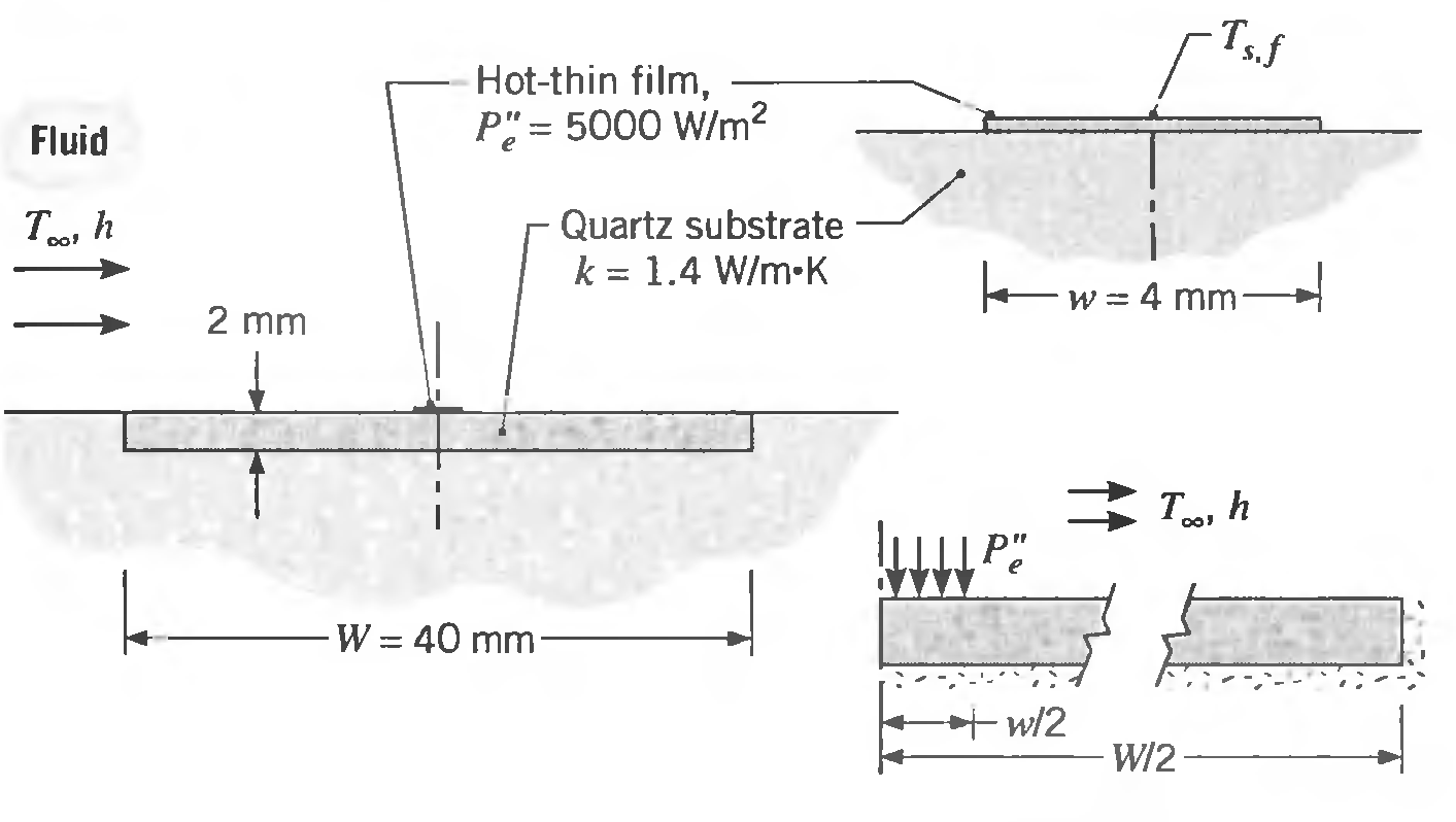
The hot-film heat flux gage shown schematically may be used to determine the convection coefficient of an adjoining fluid stream by measuring the electric power dissipation per unit area, P"e (W/m2), and the average surface temperature, Ts,f' of the film, The power dissipated in the film is
A semiconductor industry roadmap for microlithography processing requires that a 300-mm-diameter silicon wafer be maintained at a steady-state temperature of 140°C to within a uniformity of 0.1 Dc. The design of a hot-plate tool to hopefully meet this requirement is shown schematically. An
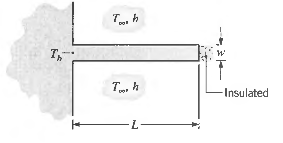
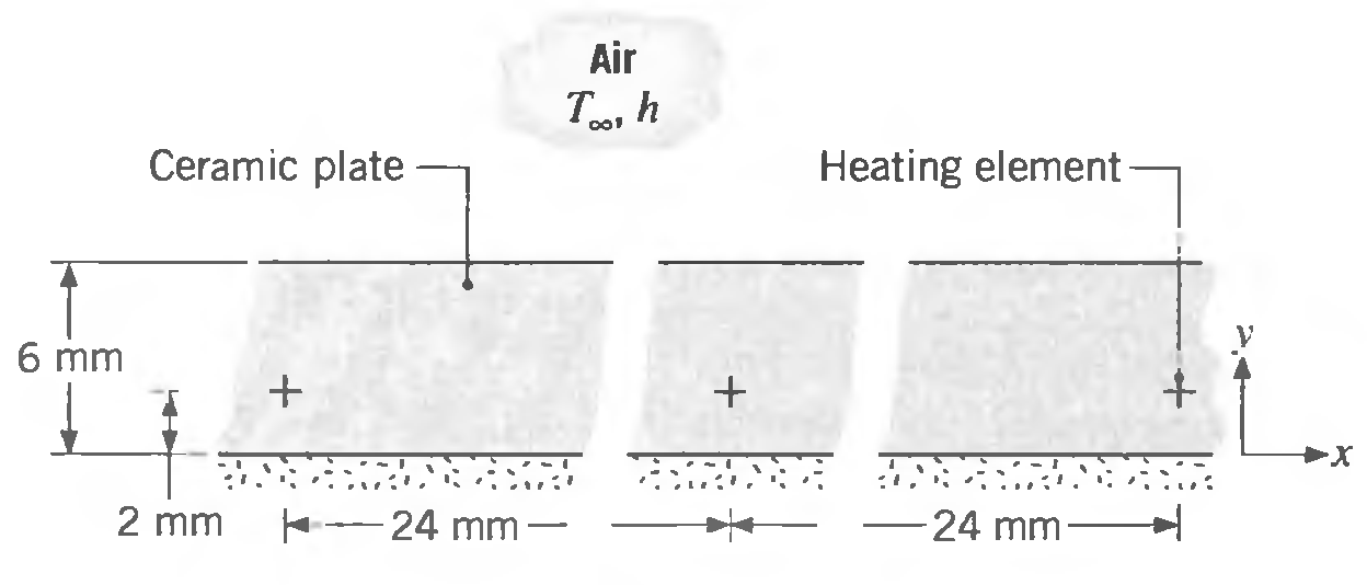
A straight fin of uniform cross section is fabricated from a material of thermal conductivity 50 W/m. K, thickness w = 6 mm, and length L = 48 mm, and is very long in the direction normal to the page. The convection heat transfer coefficient is 500 W/m2 ∙ K with an ambient air temperature of T∞
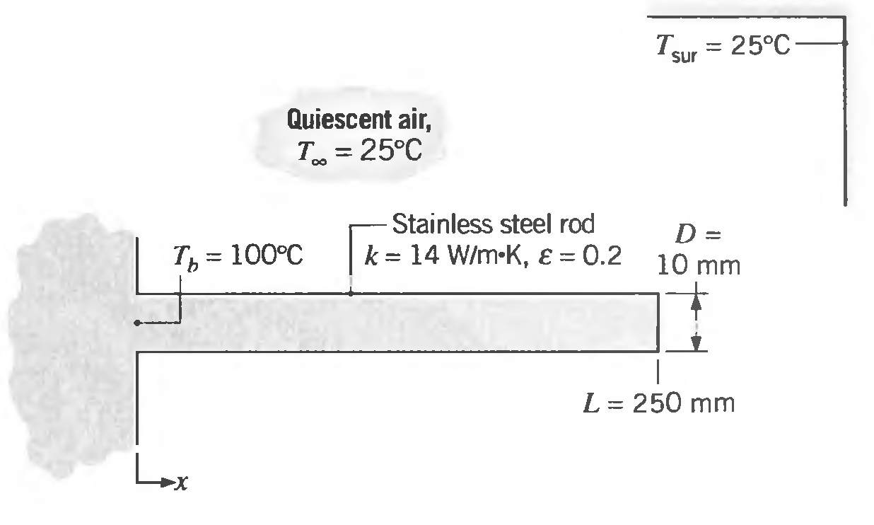
A rod of 10-mm diameter and 250-mm length has one end maintained at 100°C. The surface of the rod experiences free convection with the ambient air at 25°C and a convection coefficient that depends on the difference between the temperature of the surface and the ambient air. Specifically, the
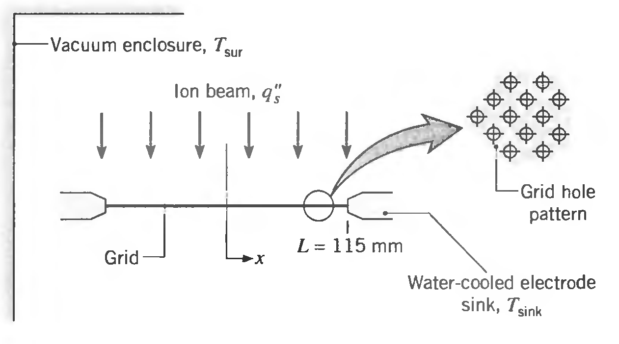
A thin metallic foil of thickness 0.25 mm with a pattern of extremely small holes serves as an acceleration grid to control the electrical potential of an ion beam. Such a grid is used in a chemical vapor deposition (CVD) process for the fabrication of semiconductors. The top surface of the grid is
Small diameter electrical heating elements dissipating 50 W/m (length normal to the sketch) are used to heat a ceramic plate of thermal conductivity 2 W/m ∙ K. The upper surface of the plate is exposed to ambient air at 30°C with a convection coefficient of 100 W/m2 ∙ K, while the lower
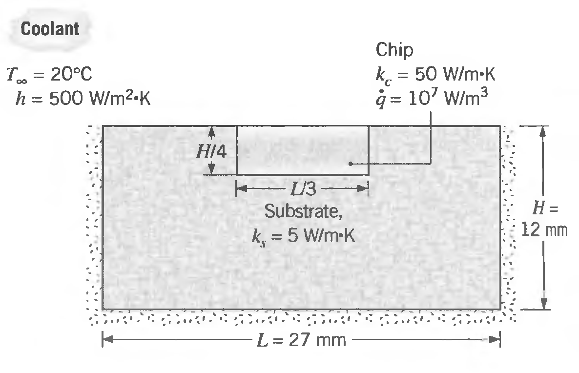
A simplified representation for cooling in very large-scale integration (VLSI) of microelectronics is shown in the sketch. A silicon chip is mounted in a dielectric substrate, and one surface of the system is convectively cooled, while the remaining surfaces are well insulated from the
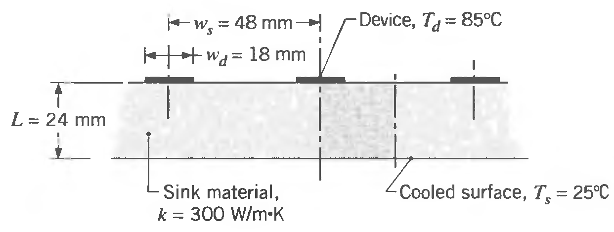
Electronic devices dissipating electrical power can be cooled by conduction to a heat sink. The lower surface of the sink is cooled, and the spacing of the devices ws, the width of the device W d' and the thickness L and thermal conductivity k of the heat sink material each affect the thermal
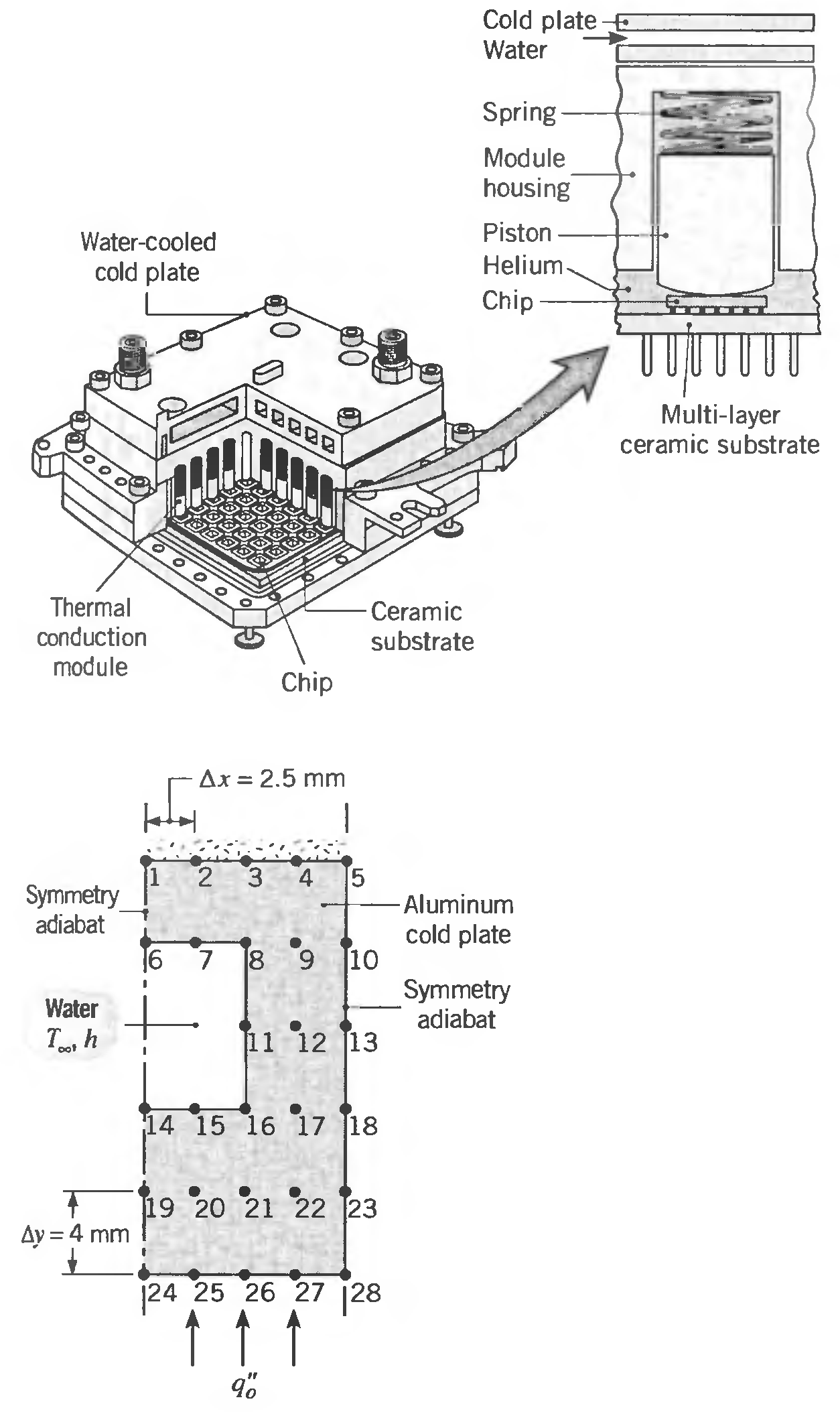
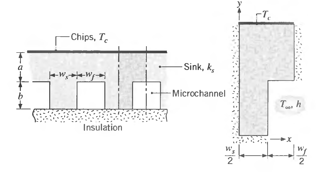
A major problem in packaging very large-scale integrated (VLSI) circuits concerns cooling of the circuit elements. The problem results from increasing levels of power dissipation within a chip, as well as from packing chips closer together in a module. A novel technique for cooling multichip
A heat sink for cooling computer chips is fabricated from copper (k s = 400 W/m' K), with machined micro channels passing a cooling fluid for which T∞ = 25°C and h = 30,000 W/m2 ∙ K. The lower side of the sink experiences no heat removal, and a preliminary heat sink design calls for dimensions
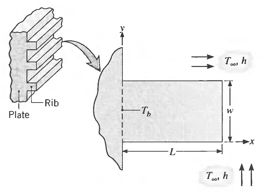
A plate (k = 10W/m ∙ K) is stiffened by a series of longitudinal ribs having a rectangular cross section with length L = 8 mm and width w = 4 mm. The base of the plate is maintained at a uniform temperature Tb = 45°C, while the rib surfaces are exposed to air at a temperature of Tx = 25°C and a
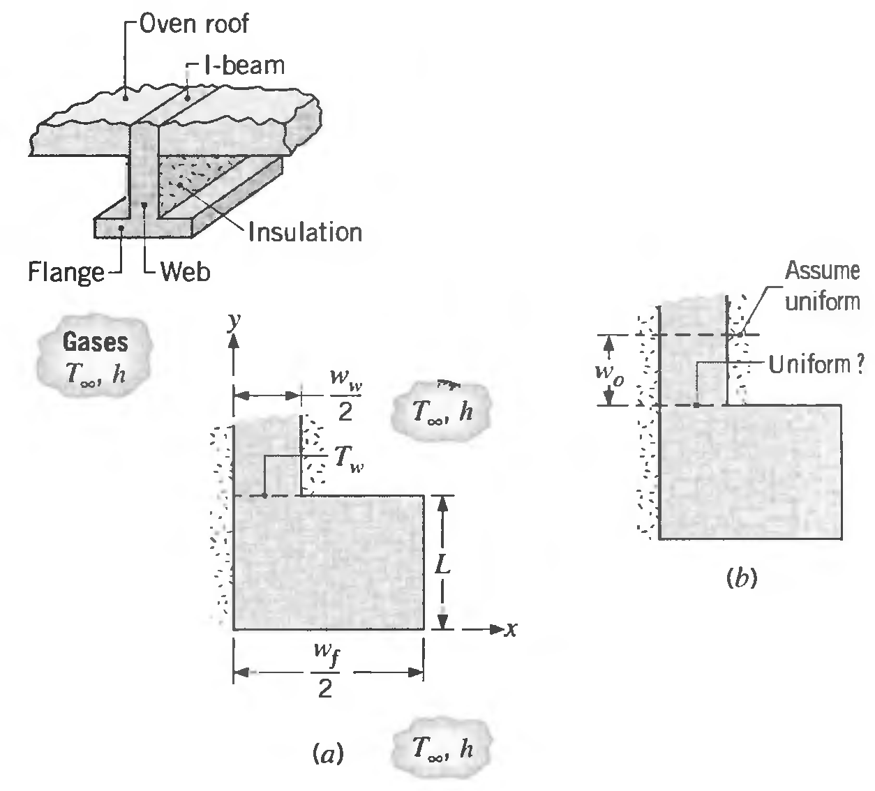
The bottom half of an I-beam providing support for a furnace roof extends into the heating zone. The web is well insulated, while the flange surfaces experience convection with hot gases at T∞. = 400°C and a convection coefficient of h = 150 W/m2 ∙ K. Consider the symmetrical element of the
Showing 8400 - 8500
of 18200
First
78
79
80
81
82
83
84
85
86
87
88
89
90
91
92
Last
Step by Step Answers
.PNG)
.PNG)
.PNG)
.PNG)
.PNG)
.PNG)
.PNG)
.PNG)
.PNG)
.PNG)
.PNG)
.PNG)
.PNG)
.PNG)
.PNG)
.PNG)
.PNG)
.PNG)
.PNG)
.PNG)
.PNG)
.PNG)
.PNG)
.PNG)
.PNG)
.PNG)
.PNG)
.PNG)
.PNG)
.PNG)
.PNG)
.PNG)
.PNG)
.PNG)
.PNG)
.PNG)
.PNG)
.PNG)
.PNG)
.PNG)
.PNG)
.PNG)
.PNG)
.PNG)
.PNG)
.PNG)
.PNG)
.PNG)
.PNG)