New Semester
Started
Get
50% OFF
Study Help!
--h --m --s
Claim Now
Question Answers
Textbooks
Find textbooks, questions and answers
Oops, something went wrong!
Change your search query and then try again
S
Books
FREE
Study Help
Expert Questions
Accounting
General Management
Mathematics
Finance
Organizational Behaviour
Law
Physics
Operating System
Management Leadership
Sociology
Programming
Marketing
Database
Computer Network
Economics
Textbooks Solutions
Accounting
Managerial Accounting
Management Leadership
Cost Accounting
Statistics
Business Law
Corporate Finance
Finance
Economics
Auditing
Tutors
Online Tutors
Find a Tutor
Hire a Tutor
Become a Tutor
AI Tutor
AI Study Planner
NEW
Sell Books
Search
Search
Sign In
Register
study help
engineering
fluid mechanics
Fluid Mechanics Fundamentals And Applications 3rd Edition Yunus Cengel, John Cimbala - Solutions
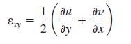
For the velocity field of Prob. 4–58, calculate the shear strain rate in the xy-plane.Data from Problem 4-58A general equation for a steady, two-dimensional velocity field that is linear in both spatial directions (x and y) iswhere U and V and the coefficients are constants. Their dimensions are
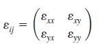
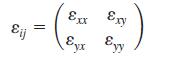
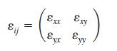
Combine your results from Probs. 4–60 and 4–61 to form the two-dimensional strain rate tensor εij in the xy-plane,Under what conditions would the x- and y-axes be principal axes?Data from Problem 4-60For the velocity field of Prob. 4–58, calculate the linear strain rates in the x- and
For the velocity field of Prob. 4–58, calculate the vorticity vector. In which direction does the vorticity vector point?Data from Problem 4-58A general equation for a steady, two-dimensional velocity field that is linear in both spatial directions (x and y) iswhere U and V and the coefficients
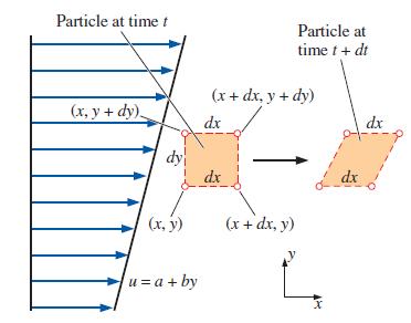
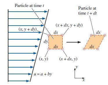
Consider steady, incompressible, two-dimensional shear flow for which the velocity field iswhere a and b are constants. Sketched in Fig. P4–64 is a small rectangular fluid particle of dimensions dx and dy at time t. The fluid particle moves and deforms with the flow such that at a later time (t +
Use two methods to verify that the flow of Prob. 4–64 is incompressible: (a) By calculating the volume of the fluid particle at both times,(b) By calculating the volumetric strain rate. Note that Prob. 4–64 should be completed before this problem.Data from problem 64Consider steady,
Consider the steady, incompressible, two-dimensional flow field of Prob. 4–64. Using the results of Prob. 4–64(a), do the following:(a) From the fundamental definition of shear strain rate (half of the rate of decrease of the angle between two initially perpendicular lines that intersect at a
Consider the steady, incompressible, two-dimensional flow field of Prob. 4–64. Using the results of Prob. 4–64(a), do the following:(a) From the fundamental definition of the rate of rotation (average rotation rate of two initially perpendicular lines that intersect at a point), calculate the
From the results of Prob. 4–67,(a) Is this flow rotational or irrotational?(b) Calculate the z-component of vorticity for this flow field.Data from Problem 67Consider the steady, incompressible, two-dimensional flow field of Prob. 4–64. Using the results of Prob. 4–64(a), do the
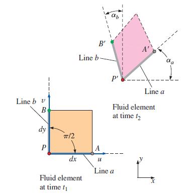
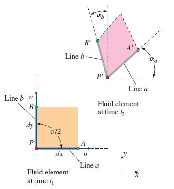
A two-dimensional fluid element of dimensions dx and dy translates and distorts as shown in Fig. P4–69 during the infinitesimal time period dt = t2 – t1. The velocity components at point P at the initial time are u and ν in the x- and y-directions, respectively. Show that the magnitude of the
A two-dimensional fluid element of dimensions dx and dy translates and distorts as shown in Fig. P4–69 during the infinitesimal time period dt = t2 – t1. The velocity components at point P at the initial time are u and ν in the x- and y-directions, respectively. Consider the line segment PA in
A two-dimensional fluid element of dimensions dx and dy translates and distorts as shown in Fig. P4–69 during the infinitesimal time period dt = t2 – t1. The velocity components at point P at the initial time are u and ν in the x- and y-directions, respectively. Show that the magnitude of the
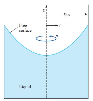
A cylindrical tank of water rotates in solid-body rotation, counterclockwise about its vertical axis (Fig. P4–73) at angular speed ṅ = 175 rpm. Calculate the vorticity of fluid particles in the tank.Figure P4-73 Free surface Liquid อ | 1 I I | I 1 Trim
Consider a steady, two-dimensional, incompressible flow field in the xy-plane. The linear strain rate in the x-direction is 2.5 s–1. Calculate the linear strain rate in the y-direction.
A cylindrical tank of radius rrim = 0.354 m rotates about its vertical axis (Fig. P4–73). The tank is partially filled with oil. The speed of the rim is 3.61 m/s in the counterclockwise direction (looking from the top), and the tank has been spinning long enough to be in solid-body rotation. For
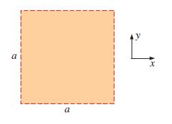
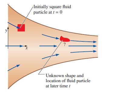
Consider a two-dimensional, incompressible flow field in which an initially square fluid particle moves and deforms. The fluid particle dimension is a at time t and is aligned with the x- and y-axes as sketched in Fig. P4–76. At some later time, the particle is still aligned with the x- and
Consider a two-dimensional, compressible flow field in which an initially square fluid particle moves and deforms. The fluid particle dimension is a at time t and is aligned with the x- and y-axes as sketched in Fig. P4–76. At some later time, the particle is still aligned with the x- and y-axes
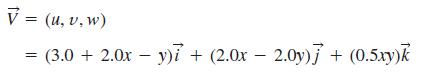
Consider the following steady, three-dimensional velocity field:Calculate the vorticity vector as a function of space (x, y, z). V = (u, v, w) (3.0+ 2.0x - y)i + (2.0x2.0y)j + (0.5xy)k
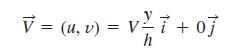
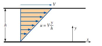
Consider fully developed Couette flow—flow between two infinite parallel plates separated by distance h, with the top plate moving and the bottom plate stationary as illustrated in Fig. P4–79. The flow is steady, incompressible, and two-dimensional in the xy-plane. The velocity field is given
For the Couette flow of Fig. P4–79, calculate the linear strain rates in the x- and y-directions, and calculate the shear strain rate εxy.FIGURE P4–79 h -V u=V²/ y x
Combine your results from Prob. 4–80 to form the two-dimensional strain rate tensor εij,Are the x- and y-axes principal axes?Data from Problem 80For the Couette flow of Fig. P4–79, calculate the linear strain rates in the x- and y-directions, and calculate the shear strain rate εxy.FIGURE
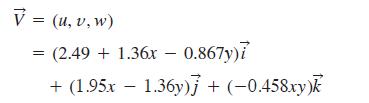
A steady, three-dimensional velocity field is given byCalculate the vorticity vector as a function of space variables (x, y, z). V = (u, v, w) = (2.49 + 1.36x - 0.867y)i + (1.95x - 1.36y)] + (-0.458xy)
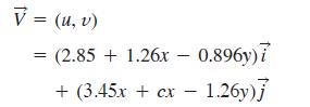
A steady, two-dimensional velocity field is given byCalculate constant c such that the flow field is irrotational. V = (u, v) = (2.85 +1.26x 0.896y)7 + (3.45x + cx - 1.26y)]
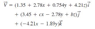
A steady, three-dimensional velocity field is given byCalculate constants b and c such that the flow field is irrotational. V = (1.35 +2.78x + 0.754y + 4.21z)i + (3.45 + cx - 2.78y + bz)] + (-4.21x 1.89y)k -
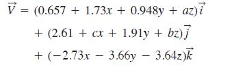
A steady, three-dimensional velocity field is given byCalculate constants a, b, and c such that the flow field is irrotational. V = (0.657 + 1.73x + 0.948y + az)i + (2.61 + cx + 1.91y + bz)] + (-2.73x 3.66y - 3.64z)k
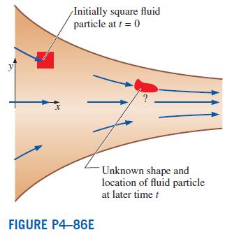
Converging duct flow is modeled by the steady, two-dimensional velocity field of Prob. 4–17. For the case in which U0 = 5.0 ft/s and b = 4.6 s-1, consider an initially square fluid particle of edge dimension 0.5 ft, centered at x = 0.5 ft and y = 1.0 ft at t = 0 (Fig. P4–86E). Carefully
Based on the results of Prob. 4–86E, verify that this converging duct flow field is indeed incompressible.Converging duct flow is modeled by the steady, two-dimensional velocity field. For the case in which U0 = 5.0 ft/s and b = 4.6 s–1, consider an initially square fluid particle of edge
Briefly explain the similarities and differences between the material derivative and the Reynolds transport theorem.
Briefly explain the purpose of the Reynolds transport theorem (RTT). Write the RTT for extensive property B as a “word equation,” explaining each term in your own words.
True or false: For each statement, choose whether the statement is true or false and discuss your answer briefly.(a) The Reynolds transport theorem is useful for transforming conservation equations from their naturally occurring control volume forms to their system forms.(b) The Reynolds transport
Consider the integralSolve it two ways:(a) Take the integral first and then the time derivative.(b) Use Leibniz theorem. Compare your results. d dt 21 x ²dx.
Solve the integralas far as you are able. хр х 21 dt :1- al
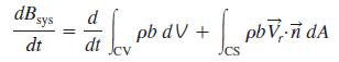
Consider the general form of the Reynolds transport theorem (RTT) given bywhere Vr(vector) is the velocity of the fluid relative to the control surface. Let Bsys be the mass m of a closed system of fluid particles. We know that for a system, dm/dt = 0 since no mass can enter or leave the system by
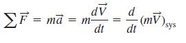
Consider the general form of the Reynolds transport theorem (RTT) as stated in Prob. 4–93. Let Bsys be the linear momentum mV(vector) of a system of fluid particles. We know that for a system, Newton’s second law isUse the RTT and Newton’s second law to derive the linear momentum equation for
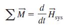
Consider the general form of the Reynolds transport theorem (RTT) as stated in Prob. 4–93. Let Bsys be the angular momentumof a system of fluid particles, where r(vector) is the moment arm. We know that for a system, conservation of angular momentum iswhere ∑M(vector) is the net moment applied
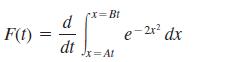
Reduce the following expression as far as possible: F(t) x=Bt d dt Jx=At e-2x² dx
Consider a steady, two-dimensional flow field in the xy-plane whose x-component of velocity is given bywhere a, b, and c are constants with appropriate dimensions. Of what form does the y-component of velocity need to be in order for the flow field to be incompressible? In other words, generate an
In a steady, two-dimensional flow field in the xy-plane, the x-component of velocity is u = ax + by + cx2 where a, b, and c are constants with appropriate dimensions. Generate a general expression for velocity component v such that the flow field is incompressible.
Combine your results from Prob. 4–100 to form the two-dimensional strain rate tensor εij in the xy-plane,Are the x- and y-axes principal axes?Data from Problem 100For the two-dimensional Poiseuille flow of Prob. 4–99, calculate the linear strain rates in the x- and y-directions, and calculate
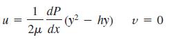
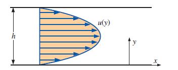
Consider fully developed two-dimensional Poiseuille flow—flow between two infinite parallel plates separated by distance h, with both the top plate and bottom plate stationary, and a forced pressure gradient dP/dx driving the flow as illustrated in Fig. P4–99. (dP/dx is constant and
For the two-dimensional Poiseuille flow of Prob. 4–99, calculate the linear strain rates in the x- and y-directions, and calculate the shear strain rate εxy.Data from Problem 99Consider fully developed two-dimensional Poiseuille flow—flow between two infinite parallel plates separated by
Consider the two-dimensional Poiseuille flow of Prob. 4–99. The fluid between the plates is water at 40°C. Let the gap height h = 1.6 mm and the pressure gradient dP/dx = –230 N/m3. Calculate and plot seven path lines from t = 0 to t = 10 s. The fluid particles are released at x = 0 and at y =
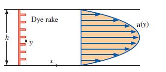
Consider the two-dimensional Poiseuille flow of Prob. 4–99. The fluid between the plates is water at 40°C. Let the gap height h = 1.6 mm and the pressure gradient dP/dx = –230 N/m3. Calculate and plot seven streaklines generated from a dye rake that introduces dye streaks at x = 0 and at y =
Repeat Prob. 4–103 except that the dye is introduced from t = 0 to t = 10 s, and the streaklines are to be plotted at t = 12 s instead of 10 s.Data from Problem 103Consider the two-dimensional Poiseuille flow. The fluid between the plates is water at 40°C. Let the gap height h = 1.6 mm and the
Compare the results of Probs. 4–103 and 4–104 and comment about the linear strain rate in the x-direction.Data from Problem 104Repeat Prob. 4–103 except that the dye is introduced from t = 0 to t = 10 s, and the streaklines are to be plotted at t = 12 s instead of 10 s.Data from Problem
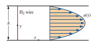
Consider the two-dimensional Poiseuille flow of Prob. 4–99. The fluid between the plates is water at 408C. Let the gap height h = 1.6 mm and the pressure gradient dP/dx = –230 N/m3. Imagine a hydrogen bubble wire stretched vertically through the channel at x = 0 (Fig. P4–106). The wire is
The velocity field of a flow is given bywhere k is a constant. If the radius of curvature of a streamline isdetermine the normal acceleration of a particle (which is normal to the streamline) passing through the position x = 1, y = 2. V = k(x² - y²)7 - 2kxy] v
The velocity field for an incompressible flow is given asDetermine if this flow is steady. Also determine the velocity and acceleration of a particle at (1, 3, 3) at t = 0.2 s. V = 5x²7- 20xy7 + 100tk.
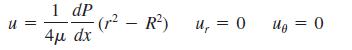
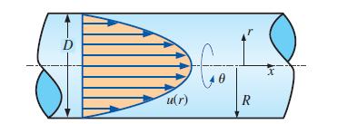
Consider fully developed axisymmetric Poiseuille flow—flow in a round pipe of radius R (diameter D = 2R), with a forced pressure gradient dP/dx driving the flow as illustrated in Fig. P4–109. (dP/dx is constant and negative.) The flow is steady, incompressible, and axisymmetric about the
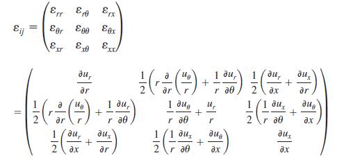
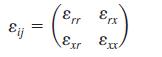
For the axisymmetric Poiseuille flow of Prob. 4–109, calculate the linear strain rates in the x- and r-directions, and calculate the shear strain rate εxr. The strain rate tensor in cylindrical coordinates (r, θ, x) and (ur, uθ, ux), isData from Problem 109Consider fully developed axisymmetric
Combine your results from Prob. 4–110 to form the axisymmetric strain rate tensor εij,Are the x- and r-axes principal axes?Data from Problem 110For the axisymmetric Poiseuille flow, calculate the linear strain rates in the x- and r-directions, and calculate the shear strain rate εxr. The strain
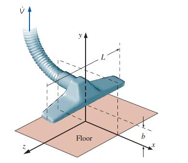
Consider the vacuum cleaner of Prob. 4–112. For the case where b = 2.0 cm, L = 35 cm, and V̇ = 0.1098 m3/s, create a velocity vector plot in the upper half of the xy-plane from x = –3 cm to 3 cm and from y = 0 cm to 2.5 cm. Draw as many vectors as you need to get a good feel of the flow field.
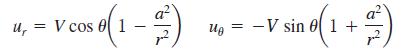
We approximate the flow of air into a vacuum cleaner attachment by the following velocity components in the centerplane (the xy-plane):where b is the distance of the attachment above the floor, L is the length of the attachment, and V̇ is the volume flow rate of air being sucked up into the hose
Consider the approximate velocity field given for the vacuum cleaner of Prob. 4–112. Calculate the flow speed along the floor. Dust particles on the floor are most likely to be sucked up by the vacuum cleaner at the location of maximum speed. Where is that location? Do you think the vacuum
In a steady, two-dimensional flow field in the xy plane, the x-component of velocity is u = ax + by + cx2 – dxy where a, b, c, and d are constants with appropriate dimensions. Generate a general expression for velocity component ν such that the flow field is incompressible.
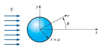
There are numerous occasions in which a fairly uniform free-stream flow encounters a long circular cylinder aligned normal to the flow (Fig. P4–116). Examples include air flowing around a car antenna, wind blowing against a flag pole or telephone pole, wind hitting electrical wires, and ocean
Consider the flow field of Prob. 4–116 (flow over a circular cylinder). Consider only the front half of the flow (x < 0). There is one stagnation point in the front half of the flow field. Where is it? Give your answer in both cylindrical (r, θ) coordinates and Cartesian (x, y) coordinates.Data
Consider the flow field of Prob. 4–116 (flow over a circular cylinder). Calculate the two linear strain rates in the rθ-plane; i.e., calculate εrr and εθθ. Discuss whether fluid line segments stretch (or shrink) in this flow field.Data from problem 116There are numerous occasions in which a
Based on your results of Prob. 4–119, discuss the compressibility (or incompressibility) of this flow.Data from problem 119Consider the flow field of Prob. 4–116 (flow over a circular cylinder). Calculate the two linear strain rates in the rθ-plane; i.e., calculate εrr and εθθ. Discuss
Consider the flow field of Prob. 4–116 (flow over a circular cylinder). Calculate εrθ, the shear strain rate in the rθ-plane. Discuss whether fluid particles in this flow deform with shear or not.Data from problem 116There are numerous occasions in which a fairly uniform free-stream flow
A steady, incompressible, two-dimensional velocity field is given bywhere the x- and y-coordinates are in meters and the magnitude of velocity is in m/s. The values of x and y at the stagnation point, respectively, are(a) 0.9375 m, 0.375 m (b) 1.563 m, –0.4375 m(c) 2.5 m, 0.7 m (d) 0.731 m,
A steady, incompressible, two-dimensional velocity field is given bywhere the x- and y-coordinates are in meters and the magnitude of velocity is in m/s. The x-component of the acceleration vector ax is(a) 0.8y (b) –1.6x (c) 2.5x – 1.6 (d) 2.56x – 4(e) 2.56x + 0.8y V = (u, v) = (2.5 -
A steady, incompressible, two-dimensional velocity field is given bywhere the x- and y-coordinates are in meters and the magnitude of velocity is in m/s. The x- and y-component of material acceleration ax and ay at the point (x = 1 m, y = 1 m), respectively, in m/s2, are(a) –1.44, 3.68 (b)
A steady, incompressible, two-dimensional velocity field is given bywhere the x- and y-coordinates are in meters and the magnitude of velocity is in m/s. The y-component of the acceleration vector ay is(a) 1.7y (b) –1.7y (c) 2.89y – 2.21 (d) 3.0x – 2.73(e) 0.84y + 1.42 V = (u, v) = (0.65
A steady, incompressible, two-dimensional velocity field is given bywhere the x- and y-coordinates are in meters and the magnitude of velocity is in m/s. The x- and y-component of material acceleration ax and ay at the point (x = 0 m, y = 0 m), respectively, in m/s2, are(a) 0.37, –1.85 (b)
A steady, incompressible, two-dimensional velocity field is given bywhere the x- and y-coordinates are in meters and the magnitude of velocity is in m/s. The x- and y-component of velocity u and ν at the point (x = 1 m, y = 2 m), respectively, in m/s, are(a) 0.54, –2.31 (b) –1.9, 0.75 (c)
The actual path traveled by an individual fluid particle over some period is called a(a) Pathline (b) Streamtube (c) Streamline(d) Streakline (e) Timeline
The locus of fluid particles that have passed sequentially through a prescribed point in the flow is called a(a) Pathline (b) Streamtube (c) Streamline(d) Streakline (e) Timeline
A curve that is everywhere tangent to the instantaneous local velocity vector is called a(a) Pathline (b) Streamtube (c) Streamline(d) Streakline (e) Timeline
An array of arrows indicating the magnitude and direction of a vector property at an instant in time is called a(a) Profiler plot (b) Vector plot (c) Contour plot(d) Velocity plot (e) Time plot
The CFD stands for(a) Compressible fluid dynamics(b) Compressed flow domain(c) Circular flow dynamics(d) Convective fluid dynamics(e) Computational fluid dynamics
Which one is not a fundamental type of motion or deformation an element may undergo in fluid mechanics?(a) Rotation (b) Converging (c) Translation(d) Linear strain (e) Shear strain
A steady, incompressible, two-dimensional velocity field is given bywhere the x- and y-coordinates are in meters and the magnitude of velocity is in m/s. The linear strain rate in the x-direction in s–1 is(a) –1.6 (b) 0.8 (c) 1.6 (d) 2.5 (e) –0.875 V = (u, v) = (2.5 - 1.6x)i + (0.7+ 1.6y)
A steady, incompressible, two-dimensional velocity field is given bywhere the x- and y-coordinates are in meters and the magnitude of velocity is in m/s. The shear strain rate in s–1 is(a) –1.6 (b) 1.6 (c) 2.5 (d) 0.7 (e) 0 V = (u, v) = = (2.5 1.6x) + (0.7 + 1.6y)] -
A steady, two-dimensional velocity field is given bywhere the x- and y-coordinates are in meters and the magnitude of velocity is in m/s. The volumetric strain rate in s–1 is(a) 0 (b) 3.2 (c) –0.8 (d) 0.8 (e) –1.6 V = (u, v) = (2.5 - 1.6x)i + (0.7+ 0.8y)]
If the vorticity in a region of the flow is zero, the flow is(a) Motionless (b) Incompressible (c) Compressible(d) Irrotational (e) Rotational
The angular velocity of a fluid particle is 20 rad/s. The vorticity of this fluid particle is(a) 20 rad/s (b) 40 rad/s (c) 80 rad/s (d) 10 rad/s(e) 5 rad/s
A steady, incompressible, two-dimensional velocity field is given bywhere the x- and y-coordinates are in meters and the magnitude of velocity is in m/s. The vorticity of this flow is(a) 0 (b) 1.2yk(vector)(c) –1.2yk(vector)(d) yk(vector)(e) 21.2xyk(vector) צן V = (u, v) = (0.75 +1.2x)i +
A steady, incompressible, two-dimensional velocity field is given bywhere the x- and y-coordinates are in meters and the magnitude of velocity is in m/s. The angular velocity of this flow is(a) 0 (b) –2yk(vector)(c) 2yk(vector)(d) –2xk(vector)(e) –xk(vector) V = (u, v) = (2xy + 1)i + (-y² -
A cart is moving at a constant absolute velocity Vcart(vector) = 5 km/h to the right. A high-speed jet of water at an absolute velocity of Vjet(vector) = 15 km/h to the right strikes the back of the car. The relative velocity of the water is(a) 0 km/h (b) 5 km/h (c) 10 km/h (d) 15 km/h (e) 20
In climates with low night-time temperatures, an energy-efficient way of cooling a house is to install a fan in the ceiling that draws air from the interior of the house and discharges it to a ventilated attic space. Consider a house whose interior air volume is 720 m3. If air in the house is to be
Air whose density is 0.082 lbm/ft3 enters the duct of an air-conditioning system at a volume flow rate of 450 ft3/min. If the diameter of the duct is 16 in, determine the velocity of the air at the duct inlet and the mass flow rate of air.
A 0.75-m3 rigid tank initially contains air whose density is 1.18 kg/m3. The tank is connected to a high-pressure supply line through a valve. The valve is opened, and air is allowed to enter the tank until the density in the tank rises to 4.95 kg/m3. Determine the mass of air that has entered the
Consider the flow of an incompressible Newtonian fluid between two parallel plates. If the upper plate moves to right with u1 = 3 m/s while the bottom one moves to the left with u2 = 0.75 m/s, what would be the net flow rate at a cross-section between two plates? Take the plate width to be b = 5 cm.
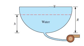
Consider a fully filled tank of semi-circular cross section tank with radius R and width of b into the page, as shown in Fig. P5-11. If the water is pumped out of the tank at flow rate of V̇ = Kh2, where K is a positive constant and h is the water depth at time t. Determine the time needed to drop
A desktop computer is to be cooled by a fan whose flow rate is 0.40 m3/min. Determine the mass flow rate of air through the fan at an elevation of 3400 m where the air density is 0.7 kg/m3. Also, if the average velocity of air is not to exceed 110 m/min, determine the minimum diameter of the casing
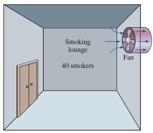
A smoking lounge is to accommodate 40 heavy smokers. The minimum fresh air requirement for smoking lounges is specified to be 30 L/s per person (ASHRAE, Standard 62, 1989). Determine the minimum required flow rate of fresh air that needs to be supplied to the lounge, and the minimum diameter of the
The minimum fresh air requirement of a residential building is specified to be 0.35 air changes per hour (ASHRAE, Standard 62, 1989). That is, 35 percent of the entire air contained in a residence should be replaced by fresh outdoor air every hour. If the ventilation requirement of a 2.7-m-high,
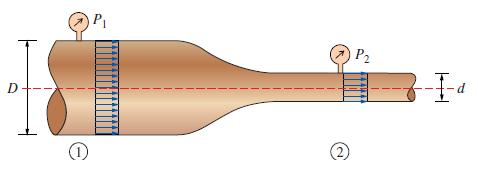
Air at 40°C flow steadily through the pipe shown in Fig. P5–16. If P1 = 50 kPa (gage), P2 = 10 kPa (gage), D = 3d, Patm ≅ 100 kPa, the average velocity at section 2 is V2 = 30 m/s, and air temperature remains nearly constant, determine the average speed at section 1.FIGURE P5–16
Air enters a nozzle steadily at 2.21 kg/m3 and 20 m/s and leaves at 0.762 kg/m3 and 150 m/s. If the inlet area of the nozzle is 60 cm2, determine (a) The mass flow rate through the nozzle,(b) The exit area of the nozzle.
At a certain location, wind is blowing steadily at 8 m/s. Determine the mechanical energy of air per unit mass and the power generation potential of a wind turbine with 50-m-diameter blades at that location. Also determine the actual electric power generation assuming an overall efficiency of 30
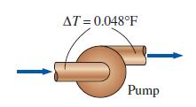
A differential thermocouple with sensors at the inlet and exit of a pump indicates that the temperature of water rises 0.048°F as it flows through the pump at a rate of 1.5 ft3/s. If the shaft power input to the pump is 23 hp and the heat loss to the surrounding air is negligible, determine the
Electric power is to be generated by installing a hydraulic turbine–generator at a site 110 m below the free surface of a large water reservoir that can supply water steadily at a rate of 900 kg/s. If the mechanical power output of the turbine is 800 kW and the electric power generation is 750
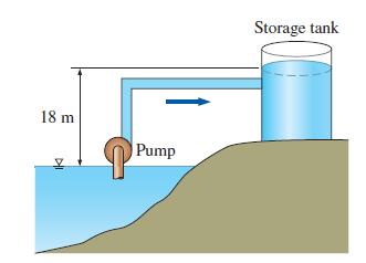
Water is pumped from a lake to a storage tank 18 m above at a rate of 70 L/s while consuming 20.4 kW of electric power. Disregarding any frictional losses in the pipes and any changes in kinetic energy, determine (a) The overall efficiency of the pump–motor unit (b) The pressure difference
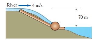
Consider a river flowing toward a lake at an average speed of 4 m/s at a rate of 500 m3/s at a location 70 m above the lake surface. Determine the total mechanical energy of the river water per unit mass and the power generation potential of the entire river at that location. River 4 m/s 70 m
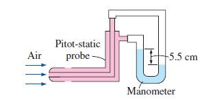
A Pitot-static probe connected to a water manometer is used to measure the velocity of air. If the deflection (the vertical distance between the fluid levels in the two arms) is 5.5 cm, determine the air velocity. Take the density of air to be 1.16 kg/m3. Air Pitot-static probe +5.5 cm Manometer
In cold climates, water pipes may freeze and burst if proper precautions are not taken. In such an occurrence, the exposed part of a pipe on the ground ruptures, and water shoots up to 42 m. Estimate the gage pressure of water in the pipe. State your assumptions and discuss if the actual pressure
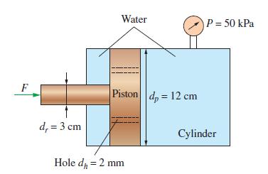
A well-fitting piston with 4 small holes in a sealed water-filled cylinder, shown in Fig. P5-67, is pushed to the right at a constant speed of 4 mm/s while the pressure in the right compartment remains constant at 50 kPa gage. Disregarding the frictional effects, determine the force F that needs to
A fluid of density ρ and viscosity μ flows through a section of horizontal converging–diverging duct. The duct cross-sectional areas Ainlet, Athroat, and Aoutlet are known at the inlet, throat (minimum area), and outlet, respectively. Average pressure Poutlet is measured at the outlet, and
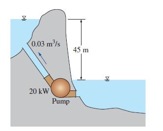
Water is pumped from a lower reservoir to a higher reservoir by a pump that provides 20 kW of useful mechanical power to the water. The free surface of the upper reservoir is 45 m higher than the surface of the lower reservoir. If the flow rate of water is measured to be 0.03 m3/s, determine the
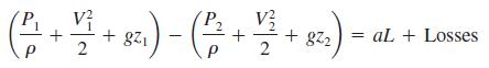
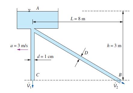
When a system is subjected to a linear rigid body motion with constant linear acceleration a along a distance L, the modified Bernoulli Equation takes the formwhere V1 and V2 are velocities relative to a fixed point and ‘Losses’ which represents frictional losses is zero when the frictional
Showing 1000 - 1100
of 1457
1
2
3
4
5
6
7
8
9
10
11
12
13
14
15
Step by Step Answers