New Semester
Started
Get
50% OFF
Study Help!
--h --m --s
Claim Now
Question Answers
Textbooks
Find textbooks, questions and answers
Oops, something went wrong!
Change your search query and then try again
S
Books
FREE
Study Help
Expert Questions
Accounting
General Management
Mathematics
Finance
Organizational Behaviour
Law
Physics
Operating System
Management Leadership
Sociology
Programming
Marketing
Database
Computer Network
Economics
Textbooks Solutions
Accounting
Managerial Accounting
Management Leadership
Cost Accounting
Statistics
Business Law
Corporate Finance
Finance
Economics
Auditing
Tutors
Online Tutors
Find a Tutor
Hire a Tutor
Become a Tutor
AI Tutor
AI Study Planner
NEW
Sell Books
Search
Search
Sign In
Register
study help
engineering
fluid mechanics
Fluid Mechanics Fundamentals And Applications 3rd Edition Yunus Cengel, John Cimbala - Solutions
Consider a 6-m-diameter spherical gate holding a body of water whose height is equal to the diameter of the gate. Atmospheric pressure acts on both sides of the gate. The vertical component of the hydrostatic force acting on this curved surface is(a) 89 kN (b) 270 kN (c) 327 kN(d) 416 kN (e) 505
A 0.75-cm-diameter spherical object is completely submerged in water. The buoyant force acting on this object is(a) 13,000 N (b) 9835 N (c) 5460 N(d) 2167 N (e) 1267 N
A 3-kg object with a density of 7500 kg/m3 is placed in water. The weight of this object in water is(a) 29.4 N (b) 25.5 N (c) 14.7 N (d) 30 N (e) 3 N
A 7-m-diameter hot air balloon is neither rising nor falling. The density of atmospheric air is 1.3 kg/m3. The total mass of the balloon including the people on board is(a) 234 kg (b) 207 kg (c) 180 kg (d) 163 kg (e) 134 kg
A 10-kg object with a density of 900 kg/m3 is placed in a fluid with a density of 1100 kg/m3. The fraction of the volume of the object submerged in water is(a) 0.637 (b) 0.716 (c) 0.818 (d) 0.90 (e) 1
Consider a cubical water tank with a side length of 3 m. The tank is half filled with water, and is open to the atmosphere with a pressure of 100 kPa. Now, a truck carrying this tank is accelerated at a rate of 5 m/s2. The maximum pressure in the water is(a) 115 kPa (b) 122 kPa (c) 129 kPa(d) 137
A 15-cm-diameter, 40-cm-high vertical cylindrical container is partially filled with 25-cm-high water. Now the cylinder is rotated at a constant speed of 20 rad/s. The maximum height difference between the edge and the center of the free surface is(a) 15 cm (b) 7.2 cm (c) 5.4 cm (d) 9.5 cm (e)
A 20-cm-diameter, 40-cm-high vertical cylindrical container is partially filled with 25-cm-high water. Now the cylinder is rotated at a constant speed of 15 rad/s. The height of water at the center of the cylinder is(a) 25 cm (b) 19.5 cm (c) 22.7 cm(d) 17.7 cm (e) 15 cm
A 15-cm-diameter, 50-cm-high vertical cylindrical container is partially filled with 30-cm-high water. Now the cylinder is rotated at a constant speed of 20 rad/s. The pressure difference between the center and edge of the container at the base surface is(a) 7327 Pa (b) 8750 Pa (c) 9930 Pa(d)
What does the word kinematics mean? Explain what the study of fluid kinematics involves.
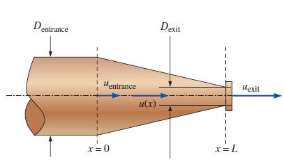
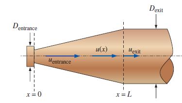
Consider steady flow of water through an axisymmetric garden hose nozzle (Fig. P4–3). Along the centerline of the nozzle, the water speed increases from uentrance to uexit as sketched. Measurements reveal that the centerline water speed increases parabolically through the nozzle. Write an
Briefly discuss the difference between derivative operators d and ∂. If the derivative ∂u/∂x appears in an equation, what does this imply about variable u?
Consider the following steady, two-dimensional velocity field:Is there a stagnation point in this flow field? If so, where is it? = 2c²xy)] V = (u, v) = (a²- (bcx)²)i + (-2cby+
A steady, two-dimensional velocity field is given byCalculate the location of the stagnation point. V = (u, v) = (-0.781 4.67x) + (-3.54 + 4.67y)] -
Consider the following steady, two-dimensional velocity field:Is there a stagnation point in this flow field? If so, where is it? V = (u, v) = (0.66 + 2.1x)i + (-2.7 2.1y)]
What is the Eulerian description of fluid motion? How does it differ from the Lagrangian description?
Is the Lagrangian method of fluid flow analysis more similar to study of a system or a control volume? Explain.
What is the Lagrangian description of fluid motion?
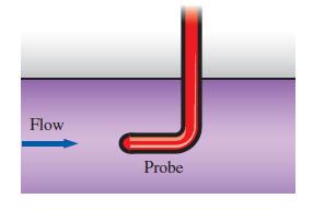
A stationary probe is placed in a fluid flow and measures pressure and temperature as functions of time at one location in the flow (Fig. P4–10C). Is this a Lagrangian or an Eulerian measurement? Explain. Flow Probe
A tiny neutrally buoyant electronic pressure probe is released into the inlet pipe of a water pump and transmits 2000 pressure readings per second as it passes through the pump. Is this a Lagrangian or an Eulerian measurement? Explain.
Define a steady flow field in the Eulerian reference frame. In such a steady flow, is it possible for a fluid particle to experience a nonzero acceleration?
List at least three other names for the material derivative, and write a brief explanation about why each name is appropriate.
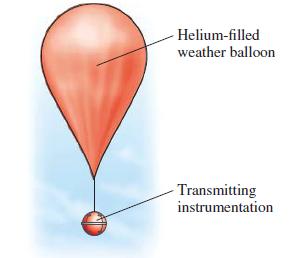
A weather balloon is launched into the atmosphere by meteorologists. When the balloon reaches an altitude where it is neutrally buoyant, it transmits information about weather conditions to monitoring stations on the ground (Fig. P4–14C). Is this a Lagrangian or an Eulerian measurement? Explain.
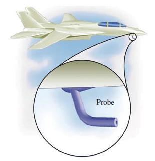
A Pitot-static probe can often be seen protruding from the underside of an airplane (Fig. P4–15C). As the airplane flies, the probe measures relative wind speed. Is this a Lagrangian or an Eulerian measurement? Explain. Probe
Is the Eulerian method of fluid flow analysis more similar to study of a system or a control volume? Explain.
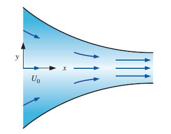
Consider steady, incompressible, two-dimensional flow through a converging duct (Fig. P4–17). A simple approximate velocity field for this flow iswhere U0 is the horizontal speed at x = 0. Note that this equation ignores viscous effects along the walls but is a reasonable approximation throughout
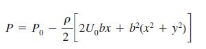
Converging duct flow is modeled by the steady, two- dimensional velocity field of Prob. 4–17. The pressure field is given bywhere P0 is the pressure at x = 0. Generate an expression for the rate of change of pressure following a fluid particle.Data from Problem 17Consider steady, incompressible,
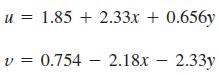
A steady, incompressible, two-dimensional velocity field is given by the following components in the xy-plane:Calculate the acceleration field (find expressions for acceleration components ax and ay), and calculate the acceleration at the point (x, y) = (–1, 2). u = 1.85 + 2.33x + 0.656y V v=
A steady, incompressible, two-dimensional velocity field is given by the following components in the xy-plane:u = 0.205 + 0.97x + 0.851yv = 20.509 + 0.953x – 0.97yCalculate the acceleration field (find expressions for acceleration components ax and ay) and calculate the acceleration at the point
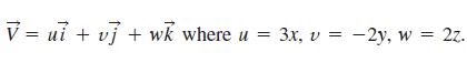
The velocity field for a flow is given byFind the streamline that will pass through the point (1, 1, 0). v=vi tuj tw where u = 3x, v + 3x, v = 2y, w = 2z.
Consider steady flow of air through the diffuser portion of a wind tunnel (Fig. P4–22). Along the centerline of the diffuser, the air speed decreases from uentrance to uexit as sketched. Measurements reveal that the centerline air speed decreases parabolically through the diffuser. Write an
For the velocity field of Prob. 4–22, calculate the fluid acceleration along the diffuser centerline as a function of x and the given parameters. For L = 1.56 m, uentrance = 24.3 m/s, and uexit = 16.8 m/s, calculate the acceleration at x = 0 and x = 1.0 m.Data from Problem 22Consider steady flow
A steady, incompressible, two-dimensional (in the xy-plane) velocity field is given byCalculate the acceleration at the point (x, y) = (–1.55, 2.07). V = (0.523 1.88x + 3.94y)i + (−2.44 + 1.26x + 1.88y)j - ·
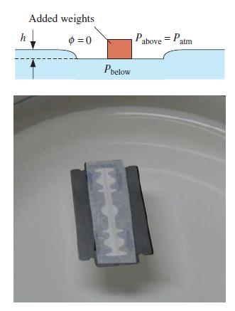
The density of stainless steel is about 8000 kg/m3 (eight times denser than water), but a razor blade can float on water, even with some added weights. The water is at 20°C. The blade shown in the photograph is 4.3 cm long and 2.2 cm wide. For simplicity, the center cut-out area of the razor blade
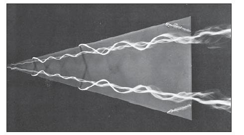
Consider the visualization of flow over a 158 delta wing in Fig. P4–30C. Are we seeing streamlines, streaklines, pathlines, or timelines? Explain. a
What is the definition of a streakline? How do streaklines differ from streamlines?
What is the definition of a pathline? What do pathlines indicate?
For the velocity field of Prob. 4–3, calculate the fluid acceleration along the nozzle centerline as a function of x and the given parameters.Data from problem 3Consider steady flow of water through an axisymmetric garden hose nozzle (Fig. P4–3). Along the centerline of the nozzle, the water
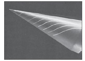
Consider the visualization of flow over a 128 cone in Fig. P4–27C. Are we seeing streamlines, streaklines, pathlines, or timelines? Explain.
What is the definition of a streamline? What do streamlines indicate?
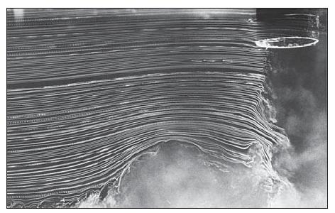
Consider the visualization of ground vortex flow in Fig. P4–31C. Are we seeing streamlines, streaklines, pathlines, or timelines? Explain.
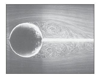
Consider the visualization of flow over a sphere in Fig. P4–32C. Are we seeing streamlines, streaklines, pathlines, or timelines? Explain.
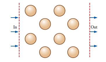
Consider a cross-sectional slice through an array of heat exchanger tubes (Fig. P4–34C). For each desired piece of information, choose which kind of flow visualization plot (vector plot or contour plot) would be most appropriate, and explain why.(a) The location of maximum fluid speed is to be
What is the definition of a timeline? How can timelines be produced in a water channel? Name an application where timelines are more useful than streaklines.
Converging duct flow (Fig. P4–17) is modeled by the steady, two-dimensional velocity field of Prob. 4–17. Generate an analytical expression for the flow streamlines.Data from Problem 17.Consider steady, incompressible, two-dimensional flow through a converging duct (Fig. P4–17). A simple
The velocity field of a flow is described by What is the pathline of a particle at a location (1 m, 2 m, 4 m) at time t = 1 s? V = (4x) + (5y + 3)j + (31²)k.
Consider the following steady, incompressible, two dimensional velocity field:Generate an analytical expression for the flow streamlines and draw several streamlines in the upper-right quadrant from x = 0 to 5 and y = 0 to 6. V = (u, v) = (4.35 + 0.656x) + (-1.22 - 0.656y)
Consider the steady, incompressible, two-dimensional velocity field of Prob. 4–37. Generate a velocity vector plot in the upper-right quadrant from x = 0 to 5 and y = 0 to 6.Data from Problem 37.Consider the following steady, incompressible, two dimensional velocity field:Generate an analytical
Consider the steady, incompressible, two-dimensional velocity field of Prob. 4–37. Generate a vector plot of the acceleration field in the upper-right quadrant from x = 0 to 5 and y = 0 to 6.Data from Problem 37.Consider the following steady, incompressible, two dimensional velocity
A steady, incompressible, two-dimensional velocity field is given bywhere the x- and y-coordinates are in m and the magnitude of velocity is in m/s.(a) Determine if there are any stagnation points in this flow field, and if so, where they are.(b) Sketch velocity vectors at several locations in the
Consider the steady, incompressible, two-dimensional velocity field of Prob. 4–40.(a) Calculate the material acceleration at the point (x = 2 m, y = 3 m).(b) Sketch the material acceleration vectors at the same array of x- and y-values as in Prob. 4–40.Data from Problem 40A steady,
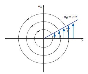
The velocity field for solid-body rotation in the rθ-plane (Fig. P4–42) is given by ur = 0 uθ = ωr where ω is the magnitude of the angular velocity (ω(vector) points in the z-direction). For the case with v = 1.5 s–1, plot a contour plot of velocity magnitude (speed). Specifically, draw
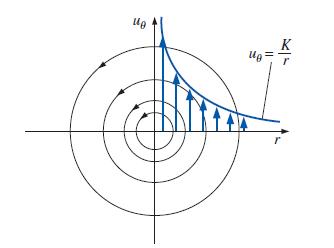
The velocity field for a line vortex in the rθ-plane (Fig. P4–43) is given by ur = 0 uθ = K/r where K is the line vortex strength. For the case with K = 1.5 m/s2, plot a contour plot of velocity magnitude (speed). Specifically, draw curves of constant speed V = 0.5, 1.0, 1.5, 2.0, and 2.5 m/s.
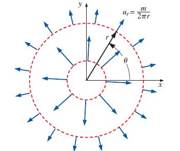
The velocity field for a line source in the rθ-plane (Fig. P4–44) is given bywhere m is the line source strength. For the case with m/(2π) = 1.5 m2/s, plot a contour plot of velocity magnitude (speed). Specifically, draw curves of constant speed V = 0.5, 1.0, 1.5, 2.0, and 2.5 m/s. Be sure to
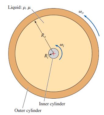
A very small circular cylinder of radius Ri is rotating at angular velocity ωi inside a much larger concentric cylinder of radius R0 that is rotating at angular velocity ωo. A liquid of density ρ and viscosity μ is confined between the two cylinders, as in Fig. P4–45. Gravitational and end
Consider the same two concentric cylinders of Prob. 4–45. This time, however, the inner cylinder is rotating, but the outer cylinder is stationary. In the limit, as the outer cylinder is very large compared to the inner cylinder (imagine the inner cylinder spinning very fast while its radius gets
Converging duct flow is modeled by the steady, two-dimensional velocity field of Prob. 4–17. For the case in which U0 = 3.56 ft/s and b = 7.66 s–1, plot several streamlines from x = 0 ft to 5 ft and y = –2 ft to 2 ft. Be sure to show the direction of the streamlines.Data from Problem
Showing 1400 - 1500
of 1457
1
2
3
4
5
6
7
8
9
10
11
12
13
14
15
Step by Step Answers