New Semester
Started
Get
50% OFF
Study Help!
--h --m --s
Claim Now
Question Answers
Textbooks
Find textbooks, questions and answers
Oops, something went wrong!
Change your search query and then try again
S
Books
FREE
Study Help
Expert Questions
Accounting
General Management
Mathematics
Finance
Organizational Behaviour
Law
Physics
Operating System
Management Leadership
Sociology
Programming
Marketing
Database
Computer Network
Economics
Textbooks Solutions
Accounting
Managerial Accounting
Management Leadership
Cost Accounting
Statistics
Business Law
Corporate Finance
Finance
Economics
Auditing
Tutors
Online Tutors
Find a Tutor
Hire a Tutor
Become a Tutor
AI Tutor
AI Study Planner
NEW
Sell Books
Search
Search
Sign In
Register
study help
engineering
mechanical vibration analysis
Mechanical Vibrations 6th Edition Singiresu S Rao - Solutions
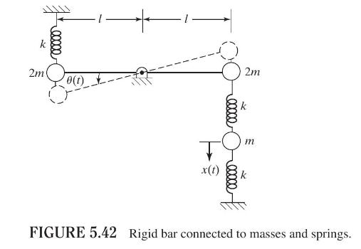
A rigid rod of negligible mass and length \(2 l\) is pivoted at the middle point and is constrained to move in the vertical plane by springs and masses, as shown in Fig. 5.42. Find the natural frequencies and mode shapes of the system. elle 2m 0(1) 2m 00000 k m x(t) k FIGURE 5.42 Rigid bar
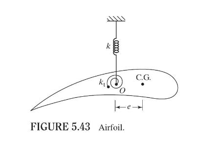
An airfoil of mass \(m\) is suspended by a linear spring of stiffness \(k\) and a torsional spring of stiffness \(k_{t}\) in a wind tunnel, as shown in Fig. 5.43. The C.G. is located at a distance of \(e\) from point \(O\). The mass moment of inertia of the airfoil about an axis passing through
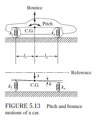
The expansion joints of a concrete highway, which are located at \(15-\mathrm{m}\) intervals, cause a series of impulses to affect cars running at a constant speed. Determine the speeds at which bounce motion and pitch motion are most likely to arise for the car of Example 5.7.Data From Example
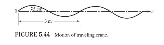
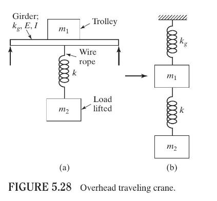
Consider the overhead traveling crane described in Problem 5.9 (Fig. 5.28). If the rails on both sides of the girder have a sinusoidally varying surface in the \(z\) direction (perpendicular to the page), as shown in Fig. 5.44, set up the equations and the initial conditions for finding the
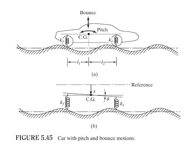
A car is modeled with a capability of pitch and bounce motions, as shown in Fig. 5.45. It travels on a rough road whose surface varies sinusoidally with an amplitude of \(0.05 \mathrm{~m}\) and a wavelength of \(10 \mathrm{~m}\). Derive the equations of motion of the car for the following data:
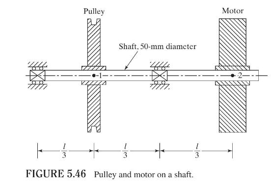
A steel shaft, of diameter \(50 \mathrm{~mm}\), is supported on two bearings and carries a pulley and a motor, as shown in Fig. 5.46. The masses of the pulley and the motor are \(100 \mathrm{~kg}\) and \(250 \mathrm{~kg}\), respectively. A transverse load applied at any point along the length of
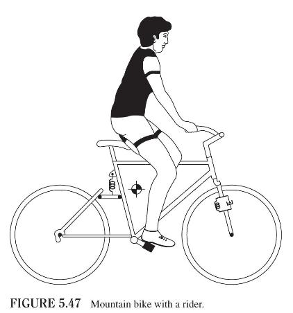
A simplified model of a mountain bike with a rider is shown in Fig. 5.47. Discuss methods of finding the vibratory response of the bicycle due to the unevenness of the terrain using a two-degree-of-freedom model. FIGURE 5.47 Mountain bike with a rider.
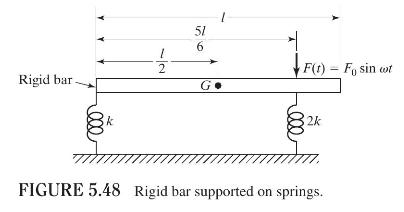
A uniform rigid bar of length \(l\) and mass \(m\) is supported on two springs and is subjected to a force \(F(t)=F_{0} \sin \omega t\), as shown in Fig. 5.48. (a) Derive the equations of motion of the bar for small displacements. (b) Discuss the nature of coupling in the system. F(t) - Fo sin cot
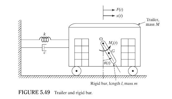
A trailer of mass \(M\), connected to a wall through a spring of stiffness \(k\) and a damper of damping coefficient \(c\), slides on a frictionless surface, as shown in Fig. 5.49. A uniform rigid bar, pin-connected to the trailer, can oscillate about the hinge point, \(O\). Derive the equations of
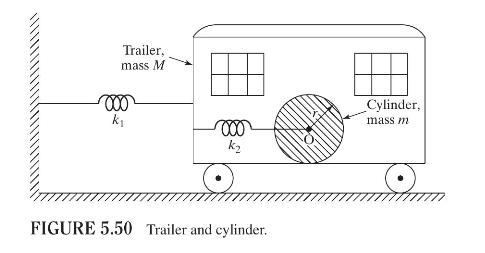
A trailer of mass \(M\) is connected to a wall through a spring of stiffness \(k_{1}\) and can move on a frictionless horizontal surface, as shown in Fig. 5.50. A uniform cylinder of mass \(m\), connected to the wall of the trailer by a spring of stiffness \(k_{2}\), can roll on the floor of the
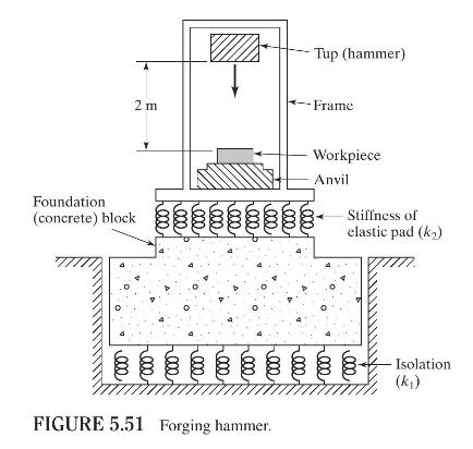
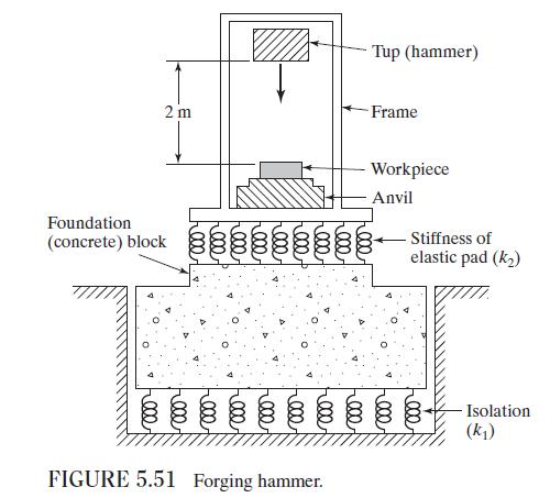
The masses of the tup, frame, anvil (along with the workpiece), and foundation block in a forging hammer (Fig. 5.51) are \(2200 \mathrm{~kg}, 22,000 \mathrm{~kg}, 35,000 \mathrm{~kg}\), and 70,000 kg, respectively.The stiffnesses of the elastic pad placed between the anvil and the foundation block
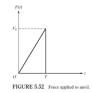
Find (a) the natural frequencies of the system, and (b) the responses of the anvil and the foundation block of the forging hammer shown in Fig. 5.51 when the time history of the force applied to the anvil is as shown in Fig. 5.52. Assume the following data:Mass of anvil and frame \(=200
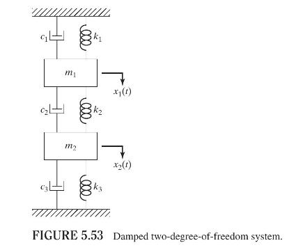
Derive the equations of motion for the free vibration of the system shown in Fig. 5.53. Assuming the solution as \(x_{i}(t)=C_{i} e^{s t}, i=1,2\), express the characteristic equation in the form\[a_{0} s^{4}+a_{1} s^{3}+a_{2} s^{2}+a_{3} s+a_{4}=0\]Discuss the nature of possible solutions,
Find the displacements \(x_{1}(t)\) and \(x_{2}(t)\) in Fig. 5.53 for \(m_{1}=1 \mathrm{~kg}, m_{2}=2 \mathrm{~kg}\), \(k_{1}=k_{2}=k_{3}=10,000 \mathrm{~N} / \mathrm{m}\), and \(c_{1}=c_{2}=c_{3}=2000 \mathrm{~N}-\mathrm{s} / \mathrm{m}\) using the initial conditions \(x_{1}(0)=0.2 \mathrm{~m},
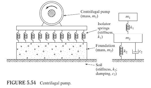
A centrifugal pump, having an unbalance of \(m e\), is supported on a rigid foundation of mass \(m_{2}\) through isolator springs of stiffness \(k_{1}\), as shown in Fig. 5.54. If the soil stiffness and damping are \(k_{2}\) and \(c_{2}\), find the displacements of the pump and the foundation for
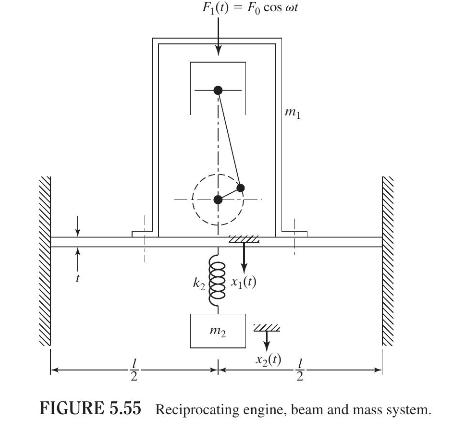
A reciprocating engine of mass \(m_{1}\) is mounted on a fixed-fixed beam of length \(l\), width \(a\), thickness \(t\), and Young's modulus \(E\), as shown in Fig. 5.55. A spring-mass system \(\left(k_{2}, m_{2}\right)\) is suspended from the beam as indicated in the figure. Find the relation
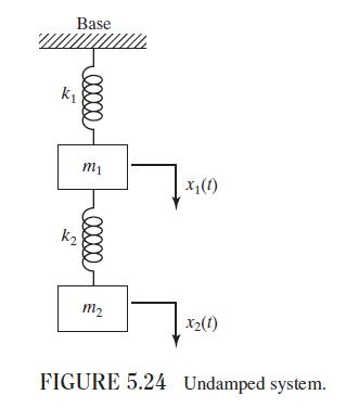
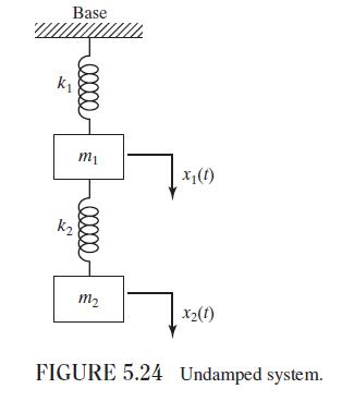
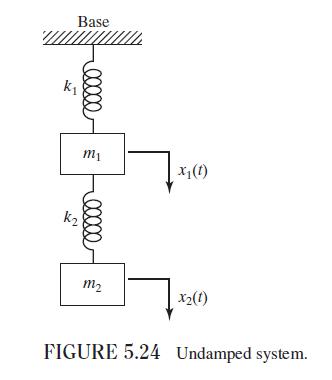
Find the steady-state response of the system shown in Fig. 5.24 by using the mechanical impedance method, when the mass \(m_{1}\) is subjected to the force \(F(t)=F_{0} \sin \omega t\) in the direction of \(x_{1}(t)\).Figure 5.24:- Base k 00000 m1 x(1) m2 x2(1) FIGURE 5.24 Undamped system.
Find the steady-state response of the system shown in Fig. 5.24 when the base is subjected to a displacement \(y(t)=Y_{0} \cos \omega t\).Figure 5.24:- Base k 00000 m1 x(1) m2 x2(1) FIGURE 5.24 Undamped system.
The mass \(m_{1}\) of the two-degree-of-freedom system shown in Fig. 5.24 is subjected to a force \(F_{0} \cos \omega t\). Assuming that the surrounding air damping is equivalent to \(c=200 \mathrm{~N}-\mathrm{s} / \mathrm{m}\), find the steady-state response of the two masses. Assume
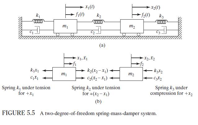
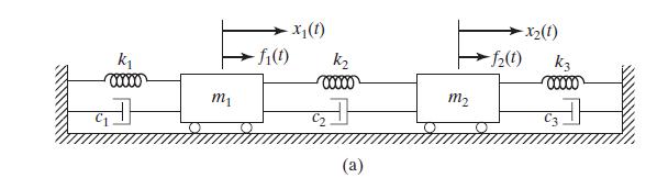
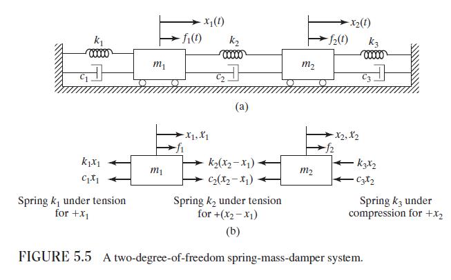
Determine the steady-state vibration of the system shown in Fig. 5.5(a), assuming that \(c_{1}=c_{2}=c_{3}=0, F_{1}(t)=F_{10} \cos \omega t\), and \(F_{2}(t)=F_{20} \cos \omega t\). -x(t) k fi(t) k -X2(1) -2(t) K3 00000 00000 m m2 kx1 m1 C Spring k under tension for +1 (a) -X1, X1 k2(x-x1) 12(12-1)
In the system shown in Fig. 5.24, the mass \(m_{1}\) is excited by a harmonic force having a maximum value of \(50 \mathrm{~N}\) and a frequency of \(2 \mathrm{~Hz}\). Find the forced amplitude of each mass for \(m_{1}=10 \mathrm{~kg}, m_{2}=5 \mathrm{~kg}, k_{1}=8000 \mathrm{~N} / \mathrm{m}\),
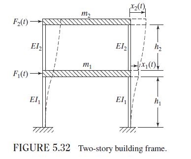
Find the response of the two masses of the two-story building frame shown in Fig. 5.32 under the ground displacement \(y(t)=0.2 \sin \pi t \mathrm{~m}\). Assume the equivalent stiffness of the lower and upper columns to be \(800 \mathrm{~N} / \mathrm{m}\) and \(600 \mathrm{~N} / \mathrm{m}\),
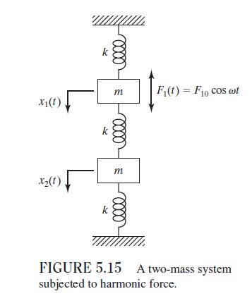
Find the forced-vibration response of the system shown in Fig. 5.15 when \(F_{1}(t)\) is a step force of magnitude \(5 \mathrm{~N}\) using the Laplace transform method. Assume \(x_{1}(0)=\dot{x}_{1}(0)=\) \(x_{2}(0)=\dot{x}_{2}(0)=0, m=1 \mathrm{~kg}\), and \(k=100 \mathrm{~N} / \mathrm{m}\). x(1)
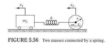
Determine the equations of motion and the natural frequencies of the system shown in Fig. 5.56. x1 x2 mp mi m. Jo FIGURE 5.56 Two masses connected by a spring.
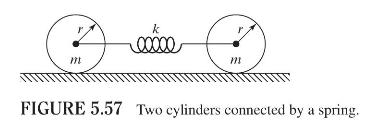
Two identical circular cylinders, of radius \(r\) and mass \(m\) each, are connected by a spring, as shown in Fig. 5.57. Determine the natural frequencies of oscillation of the system. m FIGURE 5.57 Two cylinders connected by a spring.
The differential equations of motion for a two-degree-of-freedom system are given by\[\begin{aligned}& a_{1} \ddot{x}_{1}+b_{1} x_{1}+c_{1} x_{2}=0 \\& a_{2} \ddot{x}_{2}+b_{2} x_{1}+c_{2} x_{2}=0\end{aligned}\]Derive the condition to be satisfied for the system to be degenerate.
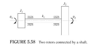
Find the angular displacements \(\theta_{1}(t)\) and \(\theta_{2}(t)\) of the system shown in Fig. 5.58 for the initial conditions \(\theta_{1}(t=0)=\theta_{1}(0), \theta_{2}(t=0)=\theta_{2}(0)\), and \(\dot{\theta}_{1}(t=0)=\dot{\theta}_{2}(t=0)=0\). k 02 FIGURE 5.58 Two rotors connected by a
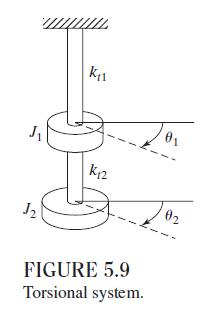
Determine the normal modes of the system shown in Fig. 5.9 with \(k_{t 1}=0\). Show that the system with \(k_{t 1}=0\) can be treated as a single-degree-of-freedom system by using the coordinate \(\alpha=\theta_{1}-\theta_{2}\). J2 k1 k12 01 FIGURE 5.9 Torsional system. 02
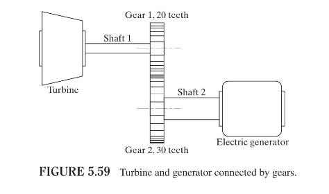
A turbine is connected to an electric generator through gears, as shown in Fig. 5.59. The mass moments of inertia of the turbine, generator, gear 1, and gear 2 are given, respectively,by \(3000,2000,500\), and \(1000 \mathrm{~kg}-\mathrm{m}^{2}\). Shafts 1 and 2 are made of steel and have diameters
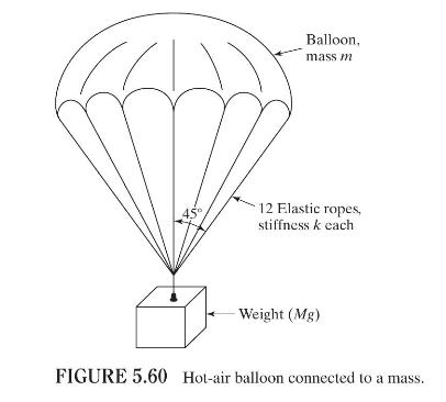
A hot-air balloon of mass \(m\) is used to lift a load, \(M g\), by means of 12 equally spaced elastic ropes, each of stiffness \(k\) (see Fig. 5.60). Find the natural frequencies of vibration of the balloon in vertical direction. State the assumptions made in your solution and discuss their
A turbine of mass moment of inertia of \(0.5 \mathrm{~kg}-\mathrm{m}^{2}\) is connected to an electric generator of mass moment of inertia of \(0.3 \mathrm{~kg}-\mathrm{m}^{2}\) by a hollow steel shaft of inner diameter inner diameter \(3 \mathrm{~cm}\), outer diameter \(5 \mathrm{~cm}\), and
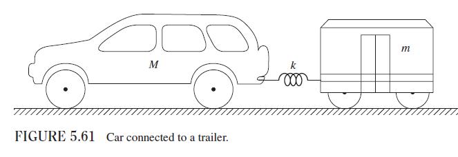
Figure 5.61 shows a \(2000-\mathrm{kg}\) car connected to a \(1000-\mathrm{kg}\) trailer by a flexible hitch having a stiffness of \(180 \mathrm{kN} / \mathrm{m}\). Assuming that both the car and the trailer can move freely on the roadway, determine the natural frequencies and mode shapes of
Find the response of the car-trailer system described in Problem 5.73 if the values of initial displacement and velocity are \(15 \mathrm{~cm}\) and \(0 \mathrm{~m} / \mathrm{s}\) for the car and \(-7.5 \mathrm{~cm}\) and \(0 \mathrm{~m} / \mathrm{s}\) for the trailer.Data From Problem 5.73:-Figure
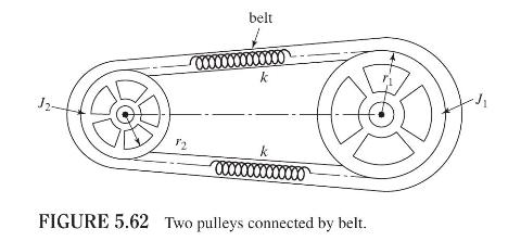
Two pulleys are driven by a belt as shown in Fig. 5.62. If the pulleys have radii \(r_{1}\) and \(r_{2}\) and mass moments of inertia \(J_{1}\) and \(J_{2}\), respectively, determine the natural frequencies of the pulley drive system. Assume the stiffness of the belt on each side as \(k\) as
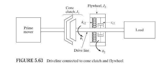
The transient vibrations of the drive line developed during the application of a cone (friction) clutch lead to unpleasant noise. To reduce the noise, a flywheel having a mass moment of inertia \(J_{2}\) is attached to the drive line through a torsional spring \(k_{t 2}\) and a viscous torsional
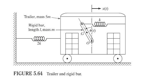
A uniform rigid bar of mass \(m\) is connected to the wall of a trailer by a spring of stiffness \(k\) (see Fig. 5.64). The trailer has a mass \(5 m\), is connected to a spring of stiffness \(2 k\), and moves on a frictionless surface. Derive the conditions necessary for the stability of the
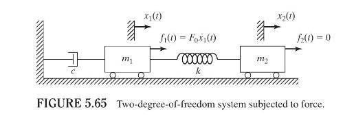
A two-degree-of-freedom system consists of masses \(m_{1}\) and \(m_{2}\) connected to a damper and a spring as shown in Fig. 5.65. If the mass \(m_{1}\) is subjected to a force proportional to its velocity, \(f_{1}(t)=a \dot{x}_{1}(t)\), determine the conditions for the stability of the system.
Derive the fourth-order differential equations of motion of the two-degree-of-freedom system shown in Fig. 5.5(a) in terms of \(x_{1}(t)\) and \(x_{2}(t)\) separately.Figure 5.5(a):- k m -fi(t) (1)x- k 00000 (a) m2 (1)x- 2(t) k3 Cz
a. Suggest a method of solving the fourth-order differential equations derived in Problem 5.79 (in terms of \(x_{1}(t)\) or \(x_{2}(t)\) ).b. How can we apply the known initial conditions \(x_{1}(0), x_{2}(0), \dot{x}_{1}(0)\) and \(\dot{x}_{2}(0)\) while solving the fourth-order differential
Derive expressions for the Laplace transform of \(x_{1}(t)\) and \(x_{2}(t)\) for the system shown in Fig. 5.5 (a) for the following data: \(m_{1}=1, m_{2}=2, k_{1}=4, k_{2}=2, k_{3}=0, c_{1}=1, c_{2}=2\), \(c_{3}=0, f_{1}(t)=F_{0} u(t)=\) step function, and \(f_{2}(t)=0\). Assume the initial
Derive expressions for the Laplace transform of \(x_{1}(t)\) and \(x_{2}(t)\) for the system shown in Fig. 5.5 (a) for the following data: \(m_{1}=1, m_{2}=2, k_{1}=4, k_{2}=2, k_{3}=0, c_{1}=1, c_{2}=2\), \(c_{3}=0, f_{1}(t)=0, f_{2}(t)=F_{0} u(t)=\) step function. Assume the initial conditions of
Find the free-vibration response of the system shown in Fig. 5.5 (a) using Laplace transform approach for the following data: \(m_{1}=2, m_{2}=4, k_{1}=8, k_{2}=4, k_{3}=0, c_{1}=0, c_{2}=0\), \(c_{3}=0\). Assume the initial conditions as \(x_{1}(0)=1, x_{2}(0)=0\), and
Find the free-vibration response of the system shown in Fig. 5.5 (a) using Laplace transform approach for the following data: \(m_{1}=2, m_{2}=4, k_{1}=8, k_{2}=4, k_{3}=0, c_{1}=0, c_{2}=2\), \(c_{3}=0\). Assume the initial conditions as \(x_{1}(0)=1, x_{2}(0)=0\), and
Find the free-vibration response of the system shown in Fig. 5.5 (a) using Laplace transform approach for the following data: \(m_{1}=2, m_{2}=8, k_{1}=8, k_{2}=4, k_{3}=0, c_{1}=0, c_{2}=0\), \(c_{3}=0\). Assume the initial conditions as \(x_{1}(0)=1, x_{2}(0)=0\), and
Find the free-vibration response of the system shown in Fig. 5.5 (a) using Laplace transform approach for the following data: \(m_{1}=1, m_{2}=8, k_{1}=8, k_{2}=4, k_{3}=0, c_{1}=0, c_{2}=0\), \(c_{3}=0\). Assume the initial conditions as \(x_{1}(0)=1, x_{2}(0)=0\), and
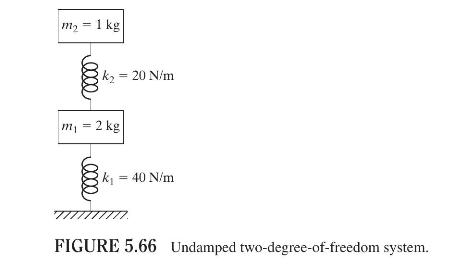
Find the response of the system shown in Fig. 5.66 with \(m_{1}=2, m_{2}=1, k_{1}=40\), and \(k_{2}=20\) for the following initial conditions using Laplace transform:i. \(x_{1}(0)=0.05, x_{2}(0)=0.10, \dot{x}_{1}(0)=0, \dot{x}_{2}(0)=0\)ii. \(x_{1}(0)=0.10, x_{2}(0)=-0.05, \dot{x}_{1}(0)=0,
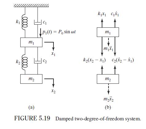
Find the steady-state response of the system considered in Example 5.13 by assuming \(p_{1}(t)=0\) and \(p_{2}(t)=P_{0} \sin \omega t\) and neglecting damping.Data From Example 5.13:- Derive the frequency transfer functions of x1(t) and x2(t) for the system shown in Fig. 5.19(a).
Find the steady-state response of the system considered in Example 5.13 by assuming \(p_{1}(t)=P_{01} \sin \omega t\) and \(p_{2}(t)=P_{02} \sin \omega t\) and neglecting damping.Data From Example 5.13:- Derive the frequency transfer functions of x1(t) and x2(t) for the system shown in Fig. 5.19(a).
Find the response of the system shown in Fig. 5.5 (a) using a numerical procedure when \(k_{1}=k, k_{2}=2 k, k_{3}=k, m_{1}=2 m, m_{2}=m, F_{2}(t)=0\), and \(F_{1}(t)\) is a rectangular pulse of magnitude \(500 \mathrm{~N}\) and duration \(0.5 \mathrm{~s}\). Assume \(m=10 \mathrm{~kg},
(a) Find the roots of the frequency equation of the system shown in Fig. 5.5 with the following data: \(m_{1}=m_{2}=50 \mathrm{~kg}, k_{1}=k_{2}=3500 \mathrm{~N} / \mathrm{m}, k_{3}=0, c_{1}=c_{2}=c_{3}=0\). (b) If the initial conditions are \(x_{1}(0)=x_{2}(0)=5 \mathrm{~cm},
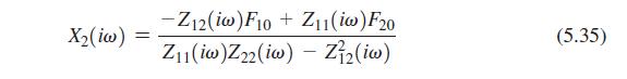
Write a computer program for finding the steady-state response of a two-degree-of-freedom system under the harmonic excitation \(F_{j}(t)=F_{j 0} e^{i \omega t}\) and \(j=1,2\) using Eqs. (5.29) and (5.35). Use this program to find the response of a system with \(m_{11}=m_{22}=2.5 \mathrm{~kg},
Find and plot the free-vibration response of the system shown in Fig. 5.24 for the following data: \(k_{1}=1000 \mathrm{~N} / \mathrm{m}, k_{2}=500 \mathrm{~N} / \mathrm{m}, m_{1}=2 \mathrm{~kg}, m_{2}=1 \mathrm{~kg}, x_{1}(0)=1, x_{2}(0)=0\), \(\dot{x}_{2}(0)=0, \dot{x}_{1}(0)=-1\).Figure 5.24:-
Find and plot the free-vibration response of the system shown in Fig. 5.24 for the following data: \(k_{1}=1000 \mathrm{~N} / \mathrm{m}, k_{2}=500 \mathrm{~N} / \mathrm{m}, m_{1}=2 \mathrm{~kg}, m_{2}=1 \mathrm{~kg}, x_{1}(0)=1, x_{2}(0)=2\), \(\dot{x}_{1}(0)=1, \dot{x}_{2}(0)=-2\).Figure 5.24:-
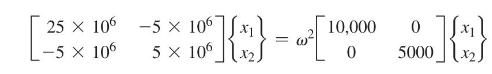
Solve the following eigenvalue problem using MATLAB: 25 x 106 -5 x -5 x 106 x1 10,000 0 = w 106 5 x 1062 0 5000 %]{*} X1
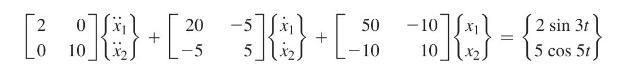
Find and plot the response of the following two-degree-of-freedom system using MATLAB:The initial conditions are \(x_{1}(0)=1, \dot{x}_{1}(0)=0, x_{2}(0)=-1\), and \(\dot{x}_{2}(0)=0\). 10]{} - {3 = 2 sin 3t 15 cos 5t) 2 0 20 -5 50 - + + 0 10 -5 52. -10
Using MATLAB, solve Problem 5.90. Use the MATLAB function stepfun for the rectangular pulse.Data From Problem 5.90:-Find the response of the system shown in Fig. 5.5(a) using a numerical procedure when \(k_{1}=k, k_{2}=2 k, k_{3}=k, m_{1}=2 m, m_{2}=m, F_{2}(t)=0\), and \(F_{1}(t)\) is a
Using MATLAB, solve Problem 5.91 (a).Data From Problem 5.91 (a):-(a) Find the roots of the frequency equation of the system shown in Fig. 5.5 with the following data: \(m_{1}=m_{2}=50 \mathrm{~kg}, k_{1}=k_{2}=3500 \mathrm{~N} / \mathrm{m}, k_{3}=0, c_{1}=c_{2}=c_{3}=0\). (b) If the initial
Using MATLAB, solve Problem 5.92. Plot the steady-state responses of masses \(m_{11}\) and \(m_{22}\).Data From Problem 5.92:-Write a computer program for finding the steady-state response of a two-degree-of-freedom system under the harmonic excitation \(F_{j}(t)=F_{j 0} e^{i \omega t}\) and
Using MATLAB, find the roots of the equation \(x^{4}-32 x^{3}+244 x^{2}-20 x-1200=0\).
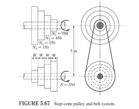
A step-cone pulley with a belt drive (Fig. 5.67) is used to change the cutting speeds in a lathe. The speed of the driving shaft is \(350 \mathrm{rpm}\) and the speeds of the output shaft are 150,250, 450 , and \(750 \mathrm{rpm}\). The diameters of the driving and the driven pulleys, corresponding
The masses of the tup, frame (along with the anvil and the workpiece), and concrete block in the forging hammer shown in Fig. 5.51 are \(1000 \mathrm{~kg}, 5000 \mathrm{~kg}\), and 25,000 kg, respectively. The tup drops onto the workpiece from a height of \(2 \mathrm{~m}\). Design suitable springs
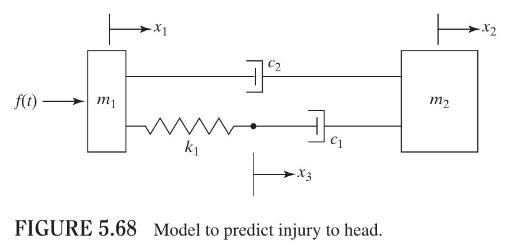
One of the models used for predicting the severity of head injury is shown in Fig. 5.68 where \(f(t)\) denotes the force of blow to the head, \(m_{1}\) is the mass of that part of the head which lies directly under the point of application of \(f(t)\) and moves with \(f(t), m_{2}\) is the rest of
Define the flexibility and stiffness influence coefficients. What is the relation between them?
Write the equations of motion of a multidegree-of-freedom system in matrix form usinga. the flexibility matrix, andb. the stiffness matrix.
Express the potential and kinetic energies of an \(n\)-degree-of-freedom system, using matrix notation.
What is a generalized mass matrix?
Why is the mass matrix \([\mathrm{m}]\) always positive definite?
Is the stiffness matrix \([k]\) always positive definite? Why?
What is the difference between generalized coordinates and Cartesian coordinates?
State Lagrange's equations.
What is an eigenvalue problem?
What is a mode shape? How is it computed?
How many distinct natural frequencies can exist for an \(n\)-degree-of-freedom system?
What is a dynamical matrix? What is its use?
How is the frequency equation derived for a multidegree-of-freedom system?
What is meant by the orthogonality of normal modes? What are orthonormal modal vectors?
What is a basis in \(n\)-dimensional space?
What is the expansion theorem? What is its importance?
Explain the modal analysis procedure.
What is a rigid-body mode? How is it determined?
What is a degenerate system?
How can we find the response of a multidegree-of-freedom system using the first few modes only?
Define Rayleigh's dissipation function.
Define these terms: proportional damping, modal damping ratio, modal participation factor.
When do we get complex eigenvalues?
What is the use of Routh-Hurwitz criterion?
True or False.For a multi-degree-of-freedom system, one equation of motion can be written for each degree of freedom.
True or False.Lagrange's equation cannot be used to derive the equations of motion of a multi-degree-of-freedom system.
True or False.The mass, stiffness, and damping matrices of a multi-degree-of-freedom system are always symmetric.
True or False.The product of stiffness and flexibility matrices of a system is always an identity matrix.
True or False.The modal analysis of a \(n\)-degree-of-freedom system can be conducted using \(r\) modes with \(r
True or False.For a damped multi-degree-of-freedom system, all the eigenvalues can be complex.
True or False.The modal damping ratio denotes damping in a particular normal mode.
True or False.A multi-degree-of-freedom system can have six of the natural frequencies equal to zero.
True or False.The generalized coordinates will always have the unit of length.
True or False.The generalized coordinates are independent of the conditions of constraint of the system.
True or False.The generalized mass matrix of a multi-degree-of-freedom system is always diagonal.
True or False.The potential and kinetic energies of a multi-degree-of-freedom system are always quadratic functions.
True or False.The mass matrix of a system is always symmetric and positive definite.
True or False.The stiffness matrix of a system is always symmetric and positive definite.
Showing 1600 - 1700
of 2655
First
10
11
12
13
14
15
16
17
18
19
20
21
22
23
24
Last
Step by Step Answers