New Semester
Started
Get
50% OFF
Study Help!
--h --m --s
Claim Now
Question Answers
Textbooks
Find textbooks, questions and answers
Oops, something went wrong!
Change your search query and then try again
S
Books
FREE
Study Help
Expert Questions
Accounting
General Management
Mathematics
Finance
Organizational Behaviour
Law
Physics
Operating System
Management Leadership
Sociology
Programming
Marketing
Database
Computer Network
Economics
Textbooks Solutions
Accounting
Managerial Accounting
Management Leadership
Cost Accounting
Statistics
Business Law
Corporate Finance
Finance
Economics
Auditing
Tutors
Online Tutors
Find a Tutor
Hire a Tutor
Become a Tutor
AI Tutor
AI Study Planner
NEW
Sell Books
Search
Search
Sign In
Register
study help
engineering
mechanical vibration analysis
Mechanical Vibrations 6th Edition Singiresu S Rao - Solutions
Fill in the Blanks.Any two successive displacements of the system, separated by a cycle, can be used to find the __________ decrement.
Fill in the Blanks.The damped natural frequency \(\left(\omega_{d}\right)\) can be expressed in terms of the undamped natural frequency \(\left(\omega_{n}\right)\) as __________.
Fill in the Blanks.The time constant denotes the time at which the initial response reduces by __________ \(\%\).
Fill in the Blanks.The term \(e^{-2 t}\) decays __________ than the term \(e^{-t}\) as time \(t\) increases.
Fill in the Blanks.In the \(s\)-plane, lines parallel to real axis denote systems having different __________ frequencies.
The natural frequency of a system with mass \(m\) and stiffness \(k\) is given by:a. \(\frac{k}{m}\)b. \(\sqrt{\frac{k}{m}}\)c. \(\sqrt{\frac{m}{k}}\)
In Coulomb damping, the amplitude of motion is reduced in each cycle by:a. \(\frac{\mu N}{k}\)b. \(\frac{2 \mu N}{k}\)c. \(\frac{4 \mu N}{k}\)
The amplitude of an undamped system subject to an initial displacement 0 and initial velocity \(\dot{x}_{0}\) is given by:a. \(\dot{x}_{0}\)b. \(\dot{x}_{0} \omega_{n}\)c. \(\frac{\dot{x}_{0}}{\omega_{n}}\)
The effect of the mass of the spring can be accounted for by adding the following fraction of its mass to the vibrating mass:a. \(\frac{1}{2}\)b. \(\frac{1}{3}\)c. \(\frac{4}{3}\)
For a viscous damper with damping constant \(c\), the damping force is:a. \(c \dot{x}\)b. \(c x\)c. \(\ddot{c x}\)
The relative sliding of components in a mechanical system causes:a. dry-friction dampingb. viscous dampingc. hysteresis damping
In torsional vibration, the displacement is measured in terms of a(n):a. linear coordinateb. angular coordinatec. force coordinate
The damping ratio, in terms of the damping constant \(c\) and critical damping constant \(\left(c_{c}\right)\), is given by:a. \(\frac{c_{c}}{c}\)b. \(\frac{c}{c_{c}}\)c. \(\sqrt{\frac{c}{c_{c}}}\)
The amplitude of an underdamped system subject to an initial displacement \(x_{0}\) and initial velocity 0 is given by:a. \(x_{0}\)b. \(2 x_{0}\)c. \(x_{0} \omega_{n}\)
The phase angle of an undamped system subject to an initial displacement \(x_{0}\) and initial velocity 0 is given by:a. \(x_{0}\)b. \(2 x_{0}\)c. 0
The energy dissipated due to viscous damping is proportional to the following power of the amplitude of motion:a. 1b. 2c. 3
For a critically damping system, the motion will be:a. periodicb. aperiodicc. harmonic
The energy dissipated per cycle in viscous damping with damping constant \(c\) during the simple harmonic motion \(x(t)=X \sin \omega_{d} t\), is given by:a. \(\pi c \omega_{d} X^{2}\)b. \(\pi \omega_{d} X^{2}\)c. \(\pi c \omega_{d} X\)
For a vibrating system with a total energy \(W\) and a dissipated energy \(\Delta W\) per cycle, the specific damping capacity is given by:a. \(\frac{W}{\Delta W}\)b. \(\frac{\Delta W}{W}\)c. \(\Delta W\)
If the characteristic roots have positive real values, the system response will be:a. stableb. unstablec. asymptotically stable
The frequency of oscillation of the response of a system will be higher if the imaginary part of the roots is:a. smallerb. zeroc. larger
If the characteristic roots have a zero imaginary part, the response of the system will be:a. oscillatoryb. nonoscillatoryc. steady
The shape of the root locus of a single-degree-of-freedom system for \(0 \leq \zeta \leq 1\) is:a. circularb. horizontal linec. radial line
The shape of the root locus of a single-degree-of-freedom system as \(k\) is varied is:a. vertical and horizontal linesb. circular arcc. radial lines
Natural frequency, \(\omega_{n}\)a. 1.3919b. 2.8284c. 1.1287d. 0.2251e. 0.1768f. 4.4429 g. 1.4142
Linear frequency, \(f_{n}\)a. 1.3919b. 2.8284c. 1.1287d. 0.2251e. 0.1768f. 4.4429 g. 1.4142
Natural time period, \(\tau_{n}\)a. 1.3919b. 2.8284c. 1.1287d. 0.2251e. 0.1768f. 4.4429 g. 1.4142
Damped frequency, \(\omega_{d}\)a. 1.3919b. 2.8284c. 1.1287d. 0.2251e. 0.1768f. 4.4429 g. 1.4142
Critical damping constant, \(c_{c}\)a. 1.3919b. 2.8284c. 1.1287d. 0.2251e. 0.1768f. 4.4429 g. 1.4142
Damping ratio, \(\zeta\)a. 1.3919b. 2.8284c. 1.1287d. 0.2251e. 0.1768f. 4.4429 g. 1.4142
Logarithmic decrement, \(\delta\)a. 1.3919b. 2.8284c. 1.1287d. 0.2251e. 0.1768f. 4.4429 g. 1.4142
\(20 \mathrm{~N}\)a. Coulomb damping with a coefficient of friction of 0.3b. Viscous damping with a damping coefficient \(1 \mathrm{~N}-\mathrm{s} / \mathrm{m}\)c. Viscous damping with a damping coefficient \(2 \mathrm{~N}-\mathrm{s} / \mathrm{m}\)d. Hysteretic damping with a hysteretic damping
\(1.5 \mathrm{~N}\)a. Coulomb damping with a coefficient of friction of 0.3b. Viscous damping with a damping coefficient \(1 \mathrm{~N}-\mathrm{s} / \mathrm{m}\)c. Viscous damping with a damping coefficient \(2 \mathrm{~N}-\mathrm{s} / \mathrm{m}\)d. Hysteretic damping with a hysteretic damping
\(30 \mathrm{~N}\)a. Coulomb damping with a coefficient of friction of 0.3b. Viscous damping with a damping coefficient \(1 \mathrm{~N}-\mathrm{s} / \mathrm{m}\)c. Viscous damping with a damping coefficient \(2 \mathrm{~N}-\mathrm{s} / \mathrm{m}\)d. Hysteretic damping with a hysteretic damping
\(25 \mathrm{~N}\)a. Coulomb damping with a coefficient of friction of 0.3b. Viscous damping with a damping coefficient \(1 \mathrm{~N}-\mathrm{s} / \mathrm{m}\)c. Viscous damping with a damping coefficient \(2 \mathrm{~N}-\mathrm{s} / \mathrm{m}\)d. Hysteretic damping with a hysteretic damping
\(10 \mathrm{~N}\)a. Coulomb damping with a coefficient of friction of 0.3b. Viscous damping with a damping coefficient \(1 \mathrm{~N}-\mathrm{s} / \mathrm{m}\)c. Viscous damping with a damping coefficient \(2 \mathrm{~N}-\mathrm{s} / \mathrm{m}\)d. Hysteretic damping with a hysteretic damping
Concentric circlesa. Different values of damped natural frequencyb. Different values of reciprocals of time constantc. Different values of damping ratiod. Different values of natural frequency
Lines parallel to real axisa. Different values of damped natural frequencyb. Different values of reciprocals of time constantc. Different values of damping ratiod. Different values of natural frequency
Lines parallel to imaginary axisa. Different values of damped natural frequencyb. Different values of reciprocals of time constantc. Different values of damping ratiod. Different values of natural frequency
Radial lines through origina. Different values of damped natural frequencyb. Different values of reciprocals of time constantc. Different values of damping ratiod. Different values of natural frequency
Asymptotically stablea. Neither decays nor growsb. Grows with oscillationsc. Grows without oscillationsd. Approaches zeroe. Grows without bound
Unstablea. Neither decays nor growsb. Grows with oscillationsc. Grows without oscillationsd. Approaches zeroe. Grows without bound
Stablea. Neither decays nor growsb. Grows with oscillationsc. Grows without oscillationsd. Approaches zeroe. Grows without bound
Divergent instabilitya. Neither decays nor growsb. Grows with oscillationsc. Grows without oscillationsd. Approaches zeroe. Grows without bound
Flutter instabilitya. Neither decays nor growsb. Grows with oscillationsc. Grows without oscillationsd. Approaches zeroe. Grows without bound
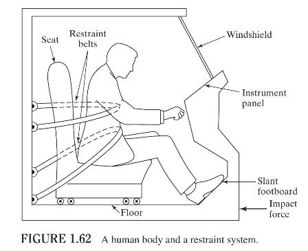
A study of the response of a human body subjected to vibration/shock is important in many applications. In a standing posture, the masses of head, upper torso, hips, and legs and the elasticity/damping of neck, spinal column, abdomen, and legs influence the response characteristics. Develop a
Figure 1.62 shows a human body and a restraint system at the time of an automobile collision [1.47]. Suggest a simple mathematical model by considering the elasticity, mass, and damping of the seat, human body, and restraints for a vibration analysis of the system. Seat Restraint belts Windshield
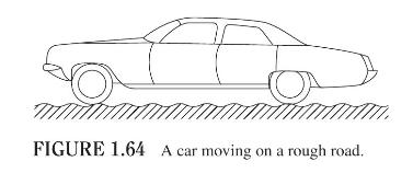
A car moving over a rough road (Fig. 1.64) can be modeled considering (a) weight of the car body, passengers, seats, front wheels, and rear wheels; (b) elasticity of tires(suspension), main springs, and seats; and (c) damping of the seats, shock absorbers, and tires. Develop three mathematical
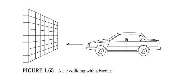
The consequences of a head-on collision of two cars can be studied by considering the impact of the car on a barrier, as shown in Fig. 1.65. Construct a mathematical model by considering the masses of the car body, engine, transmission, and suspension and the elasticity of the bumpers, radiator,
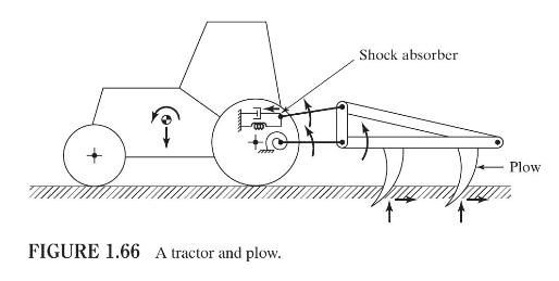
Develop a mathematical model for the tractor and plow shown in Fig. 1.66 by considering the mass, elasticity, and damping of the tires, shock absorbers, and plows (blades). ? FIGURE 1.66 A tractor and plow. Shock absorber Plow
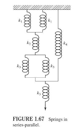
Determine the equivalent spring constant of the system shown in Fig. 1.67. k k ka FIGURE 1.67 Springs in series-parallel.
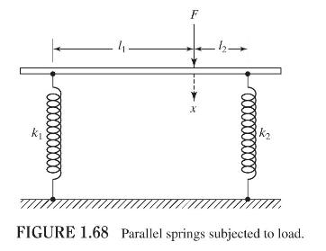
Consider a system of two springs, with stiffnesses \(k_{1}\) and \(k_{2}\), arranged in parallel as shown in Fig. 1.68. The rigid bar to which the two springs are connected remains horizontal when theforce \(F\) is zero. Determine the equivalent spring constant of the system \(\left(k_{e}\right)\)
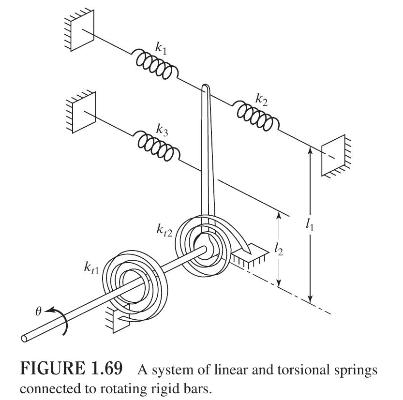
In Fig. 1.69, find the equivalent spring constant of the system in the direction of \(\theta\). k1 00000 K2 00000 K3 00000 k12 FIGURE 1.69 A system of linear and torsional springs connected to rotating rigid bars.
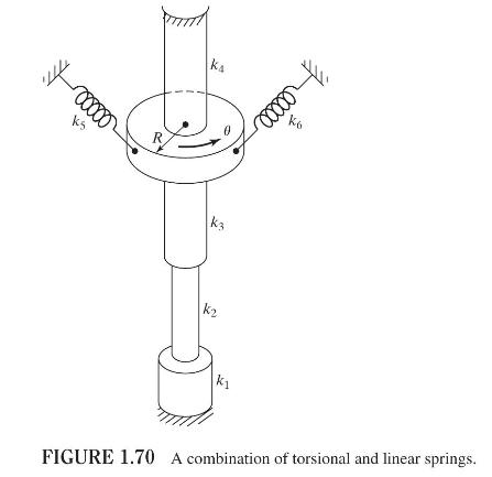
Find the equivalent torsional spring constant of the system shown in Fig. 1.70. Assume that \(k_{1}, k_{2}, k_{3}\), and \(k_{4}\) are torsional and \(k_{5}\) and \(k_{6}\) are linear spring constants. +00000 ks R ka k3 k 00000 K K FIGURE 1.70 A combination of torsional and linear springs.
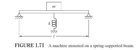
A machine of mass \(m=500 \mathrm{~kg}\) is mounted on a simply supported steel beam of length \(l=2 \mathrm{~m}\) having a rectangular cross section (depth \(=0.1 \mathrm{~m}\), width \(=1.2 \mathrm{~m}\) ) and Young's modulus \(E=2.06 \times 10^{11} \mathrm{~N} / \mathrm{m}^{2}\). To reduce the
A bar of length \(L\) and Young's modulus \(E\) is subjected to an axial force. Compare the spring constants of bars with cross sections in the form of a solid circle (of diameter \(d\) ), square (of side \(d\) ), and hollow circle (of mean diameter \(d\) and wall thickness \(t=0.1 d\) ). Determine
A cantilever beam of length \(L\) and Young's modulus \(E\) is subjected to a bending force at its free end. Compare the spring constants of beams with cross sections in the form of a solid circle (of diameter \(d\) ), square (of side \(d\) ), and hollow circle (of mean diameter \(d\) and wall
An electronic instrument, weighing \(1000 \mathrm{~N}\), is supported on a rubber mounting whose forcedeflection relationship is given by \(F(x)=157 x+0.2 x^{3}\), where the force \((F)\) and the deflection \((x)\) are in newtons and millimeters, respectively. Determine the following:a. Equivalent
The force-deflection relation of a steel helical spring used in an engine is found experimentally as \(F(x)=34.6 x+0.34 x^{2}+0.002 x^{3}\), where the force \((F)\) and deflection \((x)\) are measured in newtons and millimeters, respectively. If the spring undergoes a steady deflection of \(12.7
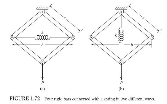
Four identical rigid bars-each of length \(a\) - are connected to a spring of stiffness \(k\) to form a structure for carrying a vertical load \(P\), as shown in Figs. 1.72(a) and (b). Find the equivalent spring constant of the system \(k_{\text {eq }}\), for each case, disregarding the masses of
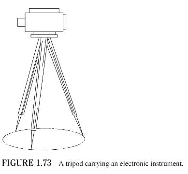
The tripod shown in Fig. 1.73 is used for mounting an electronic instrument that finds the distance between two points in space. The legs of the tripod are located symmetrically about the mid-vertical axis, each leg making an angle \(\alpha\) with the vertical. If each leg has a length \(l\) and
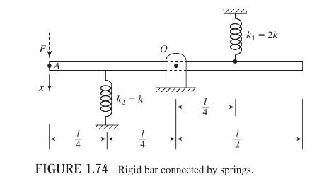
The static equilibrium position of a massless rigid bar, hinged at point \(O\) and connected with springs \(k_{1}\) and \(k_{2}\), is shown in Fig. 1.74. Assuming that the displacement \((x)\) resulting from the application of a force \(F\) at point \(A\) is small, find the equivalent spring
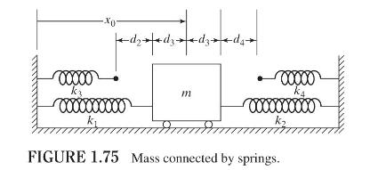
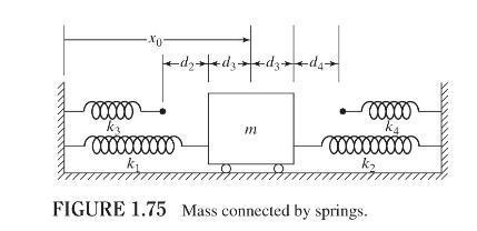
Figure 1.75 shows a system in which the mass \(m\) is directly connected to the springs with stiffnesses \(k_{1}\) and \(k_{2}\) while the spring with stiffness \(k_{3}\) or \(k_{4}\) comes into contact with the mass based on the value of the displacement of the mass. Determine the variation of the
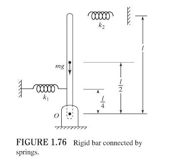
Figure 1.76 shows a uniform rigid bar of mass \(m\) that is pivoted at point \(O\) and connected by springs of stiffnesses \(k_{1}\) and \(k_{2}\). Considering a small angular displacement \(\theta\) of the rigid bar about the point \(O\), determine the equivalent spring constant associated with
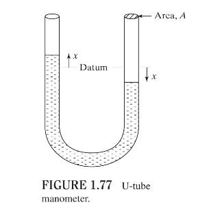
Figure 1.77 shows a U-tube manometer open at both ends and containing a column of liquid mercury of length \(l\) and specific weight \(\gamma\). Considering a small displacement \(x\) of the manometer meniscus from its equilibrium position (or datum), determine the equivalent spring constant
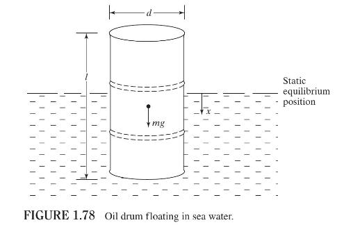
An oil drum of diameter \(d\) and mass \(m\) floats in a bath of sea water of density \(ho_{w}\) as shown in Fig. 1.78. Considering a small displacement \(x\) of the oil drum from its static equilibrium position, determine the equivalent spring constant associated with the restoring force. I I mg
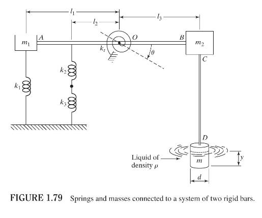
Find the equivalent spring constant and equivalent mass of the system shown in Fig. 1.79 with references to \(\theta\). Assume that the bars \(A O B\) and \(C D\) are rigid with negligible mass. m A 000 k 000 13 B m2 C D Liquid of. density p m FIGURE 1.79 Springs and masses connected to a system of
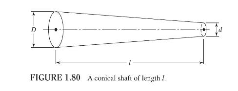
Find the length of the equivalent uniform hollow shaft of inner diameter \(d\) and thickness \(t\) that has the same axial spring constant as that of the solid conical shaft shown in Fig. 1.80. m A 000 k 000 13 B m2 C D Liquid of. density p m FIGURE 1.79 Springs and masses connected to a system of
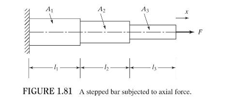
Figure 1.81 shows a three-stepped bar fixed at one end and subjected to an axial force \(F\) at the other end. The length of step \(i\) is \(l_{i}\) and its cross sectional area is \(A_{i}, i=1,2,3\). All the steps are made of the same material with Young's modulus \(E_{i}=E, i=1,2,3\).a. Find the
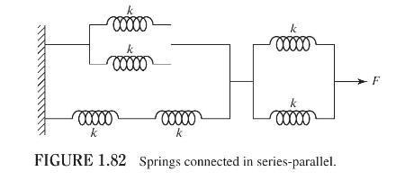
Find the equivalent spring constant of the system shown in Fig. 1.82. 00000 k 00000 00000 00000 00000 k k k FIGURE 1.82 Springs connected in series-parallel. F
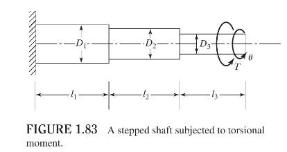
Figure 1.83 shows a three-stepped shaft fixed at one end and subjected to a torsional moment \(T\) at the other end. The length of step \(i\) is \(l_{i}\) and its diameter is \(D_{i}, i=1,2,3\). All the steps are made of the same material with shear modulus \(G_{i}=G, \mathrm{i}=1,2,3\).a. Find the
The force-deflection characteristic of a spring is described by \(F=500 x+2 x^{3}\), where the force \((F)\) is in newton and the deflection \((x)\) is in millimeters. Find (a) the linearized spring constant at \(x=10 \mathrm{~mm}\) and (b) the spring forces at \(x=9 \mathrm{~mm}\) and \(x=11
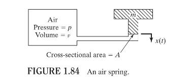
Figure 1.84 shows an air spring. This type of spring is generally used for obtaining very low natural frequencies while maintaining zero deflection under static loads. Find the spring constant of this air spring by assuming that the pressure \(p\) and volume \(v\) change adiabatically when the mass
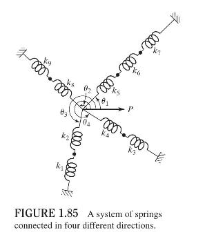
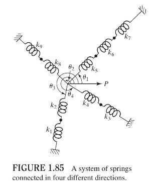
Find the equivalent spring constant of the system shown in Fig. 1.85 in the direction of the load \(P\). Ko P 000-000 K3 000 FIGURE 1.85 A system of springs connected in four different directions.
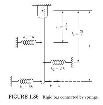
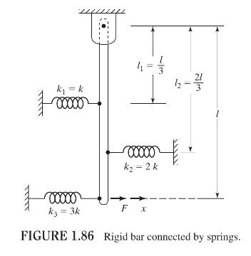
Derive the expression for the equivalent spring constant that relates the applied force \(F\) to the resulting displacement \(x\) of the system shown in Fig. 1.86. Assume the displacement of the link to be small. k = k 00000 3 12-1 k-2k 00000 k = 3k Fx FIGURE 1.86 Rigid bar connected by springs.
The spring constant of a helical spring under axial load is given by\[k=\frac{G d^{4}}{8 N D^{3}}\]where \(G\) is the shear modulus, \(d\) is the wire diameter, \(D\) is the coil diameter, and \(N\) is the number of turns. Find the spring constant and the weight of a helical spring made of steel
Two helical springs, one made of steel and the other made of aluminum, have identical values of \(d\) and \(D\). (a) If the number of turns in the steel spring is 10 , determine the number of turns required in the aluminum spring whose weight will be same as that of the steel spring. (b) Find the
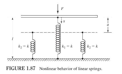
Figure 1.87 shows three parallel springs, one with stiffness \(k_{1}=k\) and each of the other two with stiffness \(k_{2}=k\). The spring with stiffness \(k_{1}\) has a length \(l\) and each of the springs with stiffness \(k_{2}\) has a length of \(l-a\). Find the force-deflection characteristic of
Design an air spring using a cylindrical container and a piston to achieve a spring constant of \(12 \mathrm{kN} / \mathrm{m}\). Assume that the maximum air pressure available is \(1.5 \mathrm{MPa}\).
The force \((F)\)-deflection \((x)\) relationship of a nonlinear spring is given by\[F=a x+b x^{3}\]where \(a\) and \(b\) are constants. Find the equivalent linear spring constant when the deflection is \(0.01 \mathrm{~m}\) with \(a=20,000 \mathrm{~N} / \mathrm{m}\) and \(b=40 \times 10^{6}
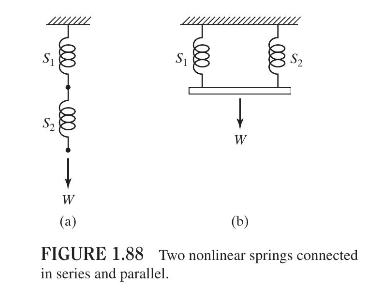
Two nonlinear springs, \(S_{1}\) and \(S_{2}\), are connected in two different ways as indicated in Fig. 1.88. The force, \(F_{i}\), in spring \(S_{i}\) is related to its deflection \(\left(x_{i}\right)\) as\[F_{i}=a_{i} x_{i}+b_{i} x_{i}^{3}, \quad i=1,2\]where \(a_{i}\) and \(b_{i}\) are
Design a steel helical compression spring to satisfy the following requirements:Spring stiffness \((k) \geq 8000 \mathrm{~N} / \mathrm{mm}\)Fundamental natural frequency of vibration \(\left(f_{1}\right) \geq 0.4\mathrm{~Hz}\)Spring index \((D /d) \geq 6\)Number of active turns \((N) \geq 10\).The
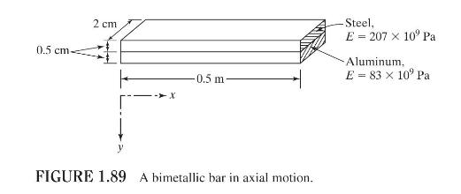
Find the spring constant of the bimetallic bar shown in Fig. 1.89 in axial motion. 0.5 cm. 2 cm -0.5 m FIGURE 1.89 A bimetallic bar in axial motion. -Steel, E=207 10 Pa Aluminum, E = 83 x 10 Pa
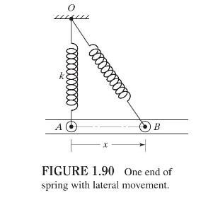
Consider a spring of stiffness \(k\) stretched by a distance \(x_{0}\) from its free length. One end of the spring is fixed at point \(O\) and the other end is connected to a roller as shown in Fig. 1.90. Theroller is constrained to move in the horizontal direction with no friction. Find the force
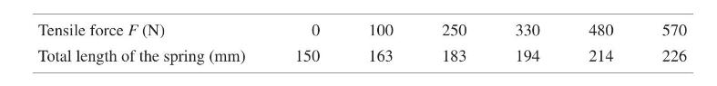
One end of a helical spring is fixed and the other end is subjected to five different tensile forces. The lengths of the spring measured at various values of the tensile forces are given below:Determine the force-deflection relation of the helical spring. Tensile force F (N) 0 100 250 330 480 570
A tapered solid steel propeller shaft is shown in Fig. 1.91. Determine the torsional spring constant of the shaft. 0.2 m- Steel, G 80 10 Pa = 1 m T 0.1 m FIGURE 1.91 A tapered solid propeller shaft.
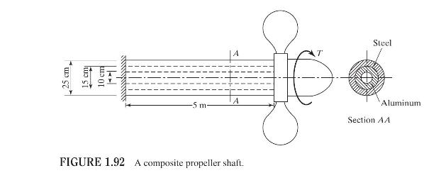
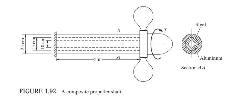
A composite propeller shaft, made of steel and aluminum, is shown in Fig. 1.92.a. Determine the torsional spring constant of the shaft.b. Determine the torsional spring constant of the composite shaft when the inner diameter of the aluminum tube is \(5 \mathrm{~cm}\) instead of \(10 \mathrm{~cm}\).
Consider two helical springs with the following characteristics:Spring 1: material—steel; number of turns- 10 ; mean coil diameter \(-0.3 \mathrm{~m}\); wire diameter\(0.05 \mathrm{~m}\); free length- \(0.4 \mathrm{~m}\); shear modulus- \(80 \times 10^{9} \mathrm{~Pa}\).Spring 2:
Solve Problem 1.44 by assuming the wire diameters of springs 1 and 2 to be \(0.125 \mathrm{~m}\) and \(0.0125 \mathrm{~m}\) instead of \(0.05 \mathrm{~m}\) and \(0.025 \mathrm{~m}\), respectively.Data From Problem 1.44:-Consider two helical springs with the following characteristics:Spring 1:
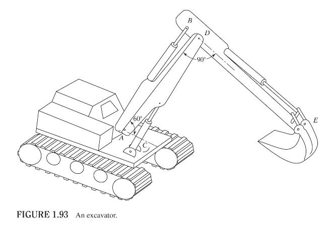
The arm \(A D\) of the excavator shown in Fig. 1.93 can be approximated as a steel tube of outer diameter \(0.25 \mathrm{~m}\), inner diameter \(0.24 \mathrm{~m}\), and length \(2.5 \mathrm{~m}\) with a viscous damping coefficient of \(70 \mathrm{~N}-\mathrm{s} / \mathrm{m}\). The arm \(D E\) can
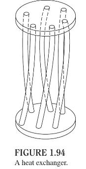
A heat exchanger consists of six identical stainless steel tubes connected in parallel as shown in Fig. 1.94. If each tube has an outer diameter \(0.00825 \mathrm{~m}\), inner diameter \(0.008 \mathrm{~m}\), and length \(1.3 \mathrm{~m}\), determine the axial stiffness and the torsional stiffness
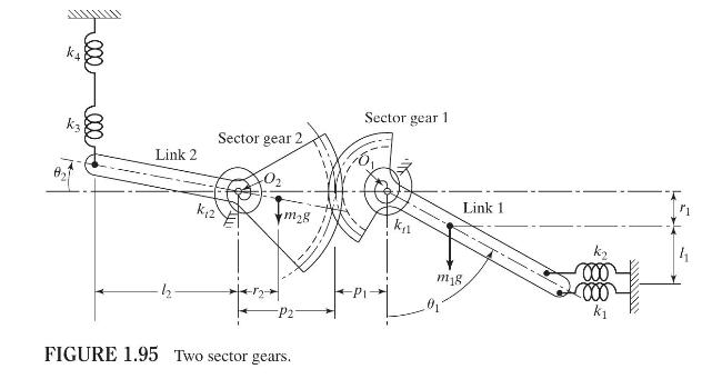
Two sector gears, located at the ends of links 1 and 2 , are engaged together and rotate about \(O_{1}\) and \(O_{2}\), as shown in Fig. 1.95. If links 1 and 2 are connected to springs \(k_{1}\) to \(k_{4}\) and \(k_{t 1}\) and \(k_{t 2}\) as shown, find the equivalent torsional spring stiffness
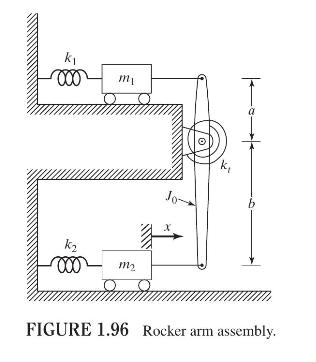
In Fig. 1.96 find the equivalent mass of the rocker arm assembly with respect to the \(x\) coordinate. k 000 k m 000 m Jo b FIGURE 1.96 Rocker arm assembly.
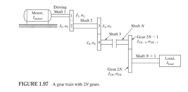
Find the equivalent mass moment of inertia of the gear train shown in Fig. 1.97 with reference to the driving shaft. In Fig. 1.97, \(J_{i}\) and \(n_{i}\) denote the mass moment of inertia and the number of teeth, respectively, of gear \(i, i=1,2, \ldots, 2 N\). Driving Motor, Jmotor Shaft 1 1. n
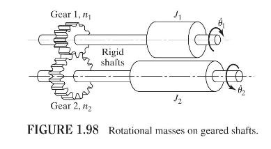
Two masses, having mass moments of inertia \(J_{1}\) and \(J_{2}\), are placed on rotating rigid shafts that are connected by gears, as shown in Fig. 1.98. If the numbers of teeth on gears 1 and 2 are \(n_{1}\) and \(n_{2}\), respectively, find the equivalent mass moment of inertia corresponding to
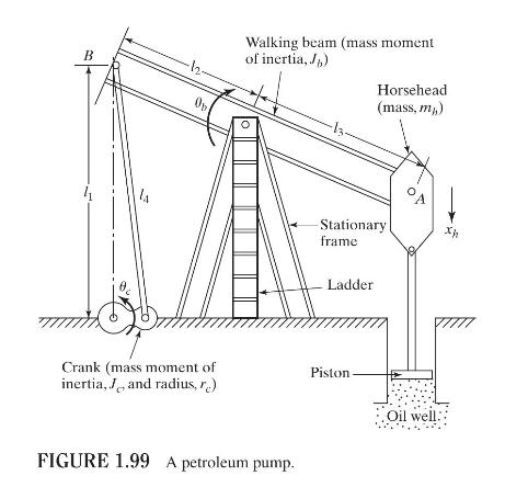
A simplified model of a petroleum pump is shown in Fig. 1.99, where the rotary motion of the crank is converted to the reciprocating motion of the piston. Find the equivalent mass, \(m_{\mathrm{eq}}\), of the system at location \(A\). B Dr Walking beam (mass moment of inertia, J) Horsehead (mass,
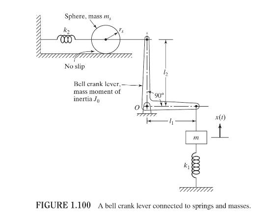
Find the equivalent mass of the system shown in Fig. 1.100. Sphere, mass m k 000 No slip Bell crank lever,- mass moment of inertia Jo 90 k1 m M 00000 x(t) FIGURE 1.100 A bell crank lever connected to springs and masses.
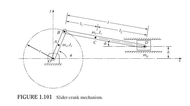
Figure 1.101 shows an offset slider-crank mechanism with a crank length \(r\), connecting rod length \(l\), and offset \(\delta\). If the crank has a mass and mass moment of inertia of \(m_{r}\) and \(J_{r}\), respectively, at its center of mass \(A\), the connecting rod has a mass and mass moment
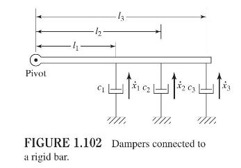
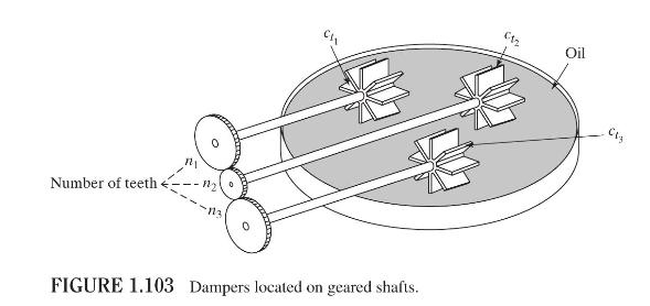
Find a single equivalent damping constant for the following cases:a. When three dampers are parallel.b. When three dampers are in series.c. When three dampers are connected to a rigid bar (Fig. 1.102) and the equivalent damper is at site \(c_{1}\).d. When three torsional dampers are located on
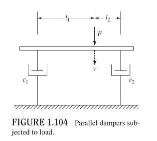
Consider a system of two dampers, with damping constants \(c_{1}\) and \(c_{2}\), arranged in parallel as shown in Fig. 1.104. The rigid bar to which the two dampers are connected remains horizontal when the force \(F\) is zero. Determine the equivalent damping constant of the system
Showing 2400 - 2500
of 2655
First
13
14
15
16
17
18
19
20
21
22
23
24
25
26
27
Step by Step Answers