New Semester
Started
Get
50% OFF
Study Help!
--h --m --s
Claim Now
Question Answers
Textbooks
Find textbooks, questions and answers
Oops, something went wrong!
Change your search query and then try again
S
Books
FREE
Study Help
Expert Questions
Accounting
General Management
Mathematics
Finance
Organizational Behaviour
Law
Physics
Operating System
Management Leadership
Sociology
Programming
Marketing
Database
Computer Network
Economics
Textbooks Solutions
Accounting
Managerial Accounting
Management Leadership
Cost Accounting
Statistics
Business Law
Corporate Finance
Finance
Economics
Auditing
Tutors
Online Tutors
Find a Tutor
Hire a Tutor
Become a Tutor
AI Tutor
AI Study Planner
NEW
Sell Books
Search
Search
Sign In
Register
study help
engineering
engineering fluid mechanics
Munson Young And Okiishi's Fundamentals Of Fluid Mechanics 8th Edition Philip M. Gerhart, Andrew L. Gerhart, John I. Hochstein - Solutions
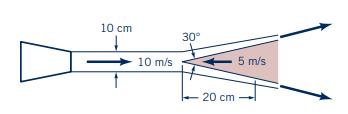
A water jet leaves a fixed nozzle with a velocity of \(10 \mathrm{~m} / \mathrm{s}\). The jet diameter is \(10 \mathrm{~cm}\). A \(30^{\circ}\) cone is pushed into the water jet at a speed of \(5 \mathrm{~m} / \mathrm{s}\). The water impinges on the cone with the jet axis and the cone axis in
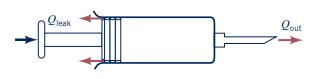
A hypodermic syringe (see Fig. P5.30) is used to apply a vaccine. If the plunger is moved forward at the steady rate of \(20 \mathrm{~mm} / \mathrm{s}\) and if vaccine leaks past the plunger at 0.1 of the volume flowrate out the needle opening, calculate the average velocity of the needle exit
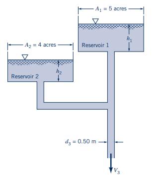
Figure P5.31 shows a two-reservoir water supply system. The water level in reservoir 1 drops at the rate of \(0.01 \mathrm{~m} / \mathrm{min}\), and the water level in reservoir 2 drops at the rate of \(0.015 \mathrm{~m} /\) \(\min\). Calculate the average velocity \(V_{3}\) in the
The Hoover Dam backs up the Colorado River and creates Lake Mead, which is approximately 115 miles long and has a surface area of approximately 225 square miles. If during flood conditions the Colorado River flows into the lake at a rate of \(45,000 \mathrm{cfs}\) and the outflow from the dam is
Storm sewer backup causes your basement to flood at the steady rate of 1 in. of depth per hour. The basement floor area is \(1500 \mathrm{ft}^{2}\). What capacity (gal/min) pump would you rent to (a) keep the water accumulated in your basement at a constant level until the storm sewer is blocked
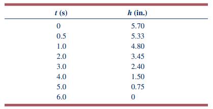
The Wide World of Fluids article "Green" 1.6-gpf standards,". When a toilet is flushed, the water depth, \(h\), in the tank as a function of time, \(t\), is as given in the table. The size of the rectangular tank is 19 in. by 7.5 in.(a) Determine the volume of water used per flush, gpf.(b) Plot the
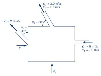
Find the force components \(F_{x}\) and \(F_{y}\) required to hold the box shown in Fig. P5.35 stationary. The fluid is oil and has specific gravity of 0.85. Neglect gravity effects. Atmospheric pressure acts around the entire box. Steady flow conditions prevail.Figure P5.35 V = 2.0 m/s 02 45 " F.
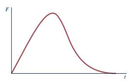
When a baseball player catches a ball, the force of the ball on her glove is as shown as a function of time in Fig. P5.36. Describe how this situation is similar to the force generated by the deflection of a jet of water by a vane. Consider many baseballs being caught in quick succession.Figure
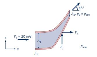
Find the horizontal and vertical forces to hold stationary the nozzle shown in Fig. P5.37. The fluid flowing through it is \(10{ }^{\circ} \mathrm{C}\) liquid water; \(A_{1}=1.0 \mathrm{~m}^{2}, A_{2}=0.25 \mathrm{~m}^{2}, V_{1}=20 \mathrm{~m} / \mathrm{s}, p_{2}=p_{\text {atm }}\), and
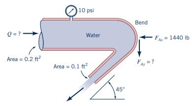
Water flows through a horizontal bend and discharges into the atmosphere as shown in Fig. P5.38. When the pressure gage reads 10 psi, the resultant \(x\)-direction anchoring force, \(F_{A x}\), in the horizontal plane required to hold the bend in place is shown on the figure. Determine the flowrate
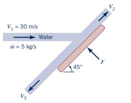
Find the magnitude of the force \(F\) required to hold the plate in Fig. P5.39 stationary.Figure P5.39 V = 30 m/s m = 5 kg/s Water 45 F
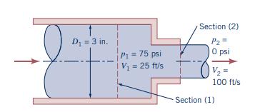
Water enters the horizontal, circular cross-sectional, sudden contraction nozzle sketched in Fig. P5.40 at section (1) with a uniformly distributed velocity of \(25 \mathrm{ft} / \mathrm{s}\) and a pressure of \(75 \mathrm{psi}\). The water exits from the nozzle into the atmosphere at section (2)
A truck carrying chickens is too heavy for a bridge that it needs to cross. The empty truck is within the weight limits; with the chickens it is overweight. It is suggested that if one could get the chickens to fly around the truck (i.e., by banging on the truck side) it would be safe to cross the
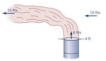
Exhaust (assumed to have the properties of standard air) leaves the 4-ft-diameter chimney shown in Video V5.4 and Fig. P5.42 with a speed of \(6 \mathrm{ft} / \mathrm{s}\). Because of the wind, after a few diameters downstream the exhaust flows in a horizontal direction with the speed of the wind,
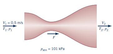
Air at \(T_{1}=300 \mathrm{~K}, p_{1}=303 \mathrm{kPa}\), and \(V_{1}=0.5 \mathrm{~m} / \mathrm{s}\) enters the Venturi shown in Fig. P5.43. The air leaves at \(T_{2}=220 \mathrm{~K}\) and \(p_{2}=\) \(101 \mathrm{kPa} ; A_{1}=0.6 \mathrm{~m}^{2}\) and \(A_{2}=1.0 \mathrm{~m}^{2}\). Calculate the
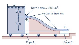
Water flows steadily from a tank mounted on a cart as shown in Fig. P5.44. After the water jet leaves the nozzle of the tank, it falls and strikes a vane attached to another cart. The cart's wheels are frictionless, and the fluid is inviscid. (a) Determine the speed of the water leaving the tank,
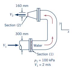
Determine the magnitude and direction of the anchoring force needed to hold the horizontal elbow and nozzle combination shown in Fig. P5.45 in place. Atmospheric pressure is \(100 \mathrm{kPa}(\mathrm{abs})\). The gage pressure at section (1) is \(100 \mathrm{kPa}\). At section (2), the water exits
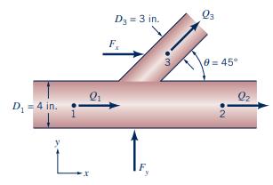
Figure P5.46 shows a lateral pipe fitting. This particular fitting has a mainline diameter of \(4.0 \mathrm{in}\). The diameter of the lateral is \(3.0 \mathrm{in}\)., and the lateral angle is \(45^{\circ} ; 60^{\circ} \mathrm{F}\) water is flowing in the lateral. Measurements show that the
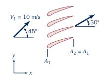
Water flows steadily between fixed vanes, as shown in Fig. P5.47. Find the \(x\) and \(y\) components of the water's force on the vanes. The total volume flow rate is \(100 \mathrm{~m}^{3} / \mathrm{s}\), pressure \(p_{1}=150 \mathrm{kPa}\), and pressure \(p_{2}=101 \mathrm{kPa}\).Figure P5.47 V =
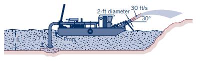
The hydraulic dredge shown in Fig. P5.48 is used to dredge sand from a river bottom. Estimate the thrust needed from the propeller to hold the boat stationary. Assume the specific gravity of the sand/water mixture is \(S G=1.4\).Figure P5.48 9 ft Prop 2-ft diameter 30 ft/s 30
A static thrust stand is to be designed for testing a specific jet engine, knowing the following conditions for a typical test.\[ \begin{aligned} \text { intake air velocity } & =700 \mathrm{ft} / \mathrm{s} \\ \text { exhaust gas velocity } & =1640 \mathrm{ft} / \mathrm{s} \\ \text { intake
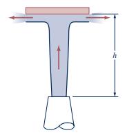
A vertical jet of water leaves a nozzle at a speed of \(10 \mathrm{~m} / \mathrm{s}\) and a diameter of \(20 \mathrm{~mm}\). It suspends a plate having a mass of \(1.5 \mathrm{~kg}\) as indicated in Fig. P5.50. What is the vertical distance \(h\) ?Figure P5.50 h
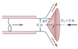
A horizontal, circular cross-sectional jet of air having a diameter of 6 in. strikes a conical deflector as shown in Fig. P5.51. A horizontal anchoring force of \(5 \mathrm{lb}\) is required to hold the cone in place. Estimate the nozzle flowrate in \(\mathrm{ft}^{3} / \mathrm{s}\). The magnitude
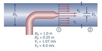
Calculate the pressure change \(\left(p_{2}-p_{1}\right)\) for the jet pump shown in Fig. P5.52. The fluid is \(20{ }^{\circ} \mathrm{C}\) water. Assume negligible friction at the walls and uniform pressure over each flow area.Figure P5.52 Do Do = 1.0 m D = 0.25 m V = 1.07 m/s V = 4.0 m/s (1) 2
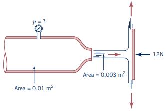
Air flows into the atmosphere from a nozzle and strikes a vertical plate as shown in Fig. P5.53. A horizontal force of \(12 \mathrm{~N}\) is required to hold the plate in place. Determine the reading on the pressure gage. Assume the flow to be incompressible and frictionless.Figure P5.53 p = ? Area
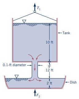
Water flows from a large tank into a dish as shown in Fig. P5.54. (a) If at the instant shown the tank and the water in it weigh \(W_{1} \mathrm{lb}\), what is the tension, \(T_{1}\), in the cable supporting the tank? (b) If at the instant shown the dish and the water in it weigh \(W_{2}
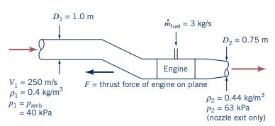
Figure P5.55 shows the configuration of the center (tailmounted) jet engine on an airliner. The airliner is cruising at altitude, and the velocities shown are relative to an observer on board. Calculate the thrust force that the engine exerts on the airplane.Figure P5.55 D = 1.0 m mtuel = 3 kg/s D
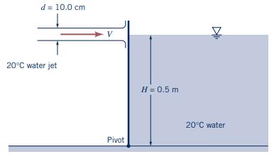
The plate shown in Fig. P5.56 is \(0.5 \mathrm{~m}\) wide perpendicular to the paper. Calculate the velocity of the water jet required to hold the plate upright.Figure P5.56 d = 10.0 cm 20C water jet V H = 0.5 m D Pivot 20C water
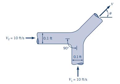
Two water jets of equal size and speed strike each other as shown in Fig. P5.57. Determine the speed, \(V\), and direction, \(\theta\), of the resulting combined jet. Gravity is negligible.Figure P5.57 V = 10 ft/s 0.1 ft 90 0.1 ft V = 10 ft/s
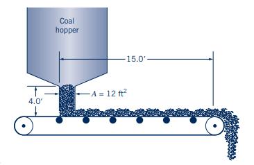
Figure P5.58 shows coal being dropped from a hopper onto a conveyor belt at a constant rate of \(25 \mathrm{ft}^{3} / \mathrm{s}\). The coal has a specific gravity ranging from 1.12 to 1.50. The belt has a speed of \(5.0 \mathrm{ft} / \mathrm{s}\) and a loaded length of \(15.0 \mathrm{ft}\).
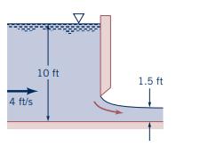
Determine the magnitude of the horizontal component of the anchoring force required to hold in place the sluice gate shown in Fig. 5.59. Compare this result with the size of the horizontal component of the anchoring force required to hold in place the sluice gate when it is closed and the depth of
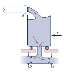
Water flows steadily into and out of a tank that sits on frictionless wheels as shown in Fig. P5.60. Determine the diameter \(D\) so that the tank remains motionless if \(F=0\).Figure P5.60 TD
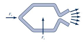
The rocket shown in Fig. P5.61 is held stationary by the horizontal force, \(F_{x}\), and the vertical force, \(F_{z}\). The velocity and pressure of the exhaust gas are \(5000 \mathrm{ft} / \mathrm{s}\) and \(20 \mathrm{psia}\) at the nozzle exit, which has a cross section area of \(60
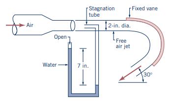
Air discharges from a 2-in.-diameter nozzle and strikes a curved vane, which is in a vertical plane as shown in Fig. P5.62. A stagnation tube connected to a water U-tube manometer is located in the free air jet. Determine the horizontal component of the force that the air jet exerts on the vane.
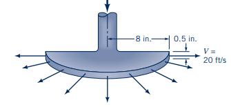
Water is sprayed radially outward over \(180^{\circ}\) as indicated in Fig. P5.63. The jet sheet is in the horizontal plane. If the jet velocity at the nozzle exit is \(20 \mathrm{ft} / \mathrm{s}\), determine the direction and magnitude of the resultant horizontal anchoring force required to hold
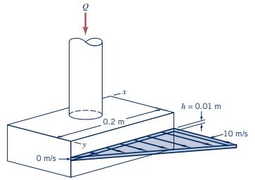
A sheet of water of uniform thickness \((h=0.01 \mathrm{~m})\) flows from the device shown in Fig. P5.64. The water enters vertically through the inlet pipe and exits horizontally with a speed that varies linearly from 0 to \(10 \mathrm{~m} / \mathrm{s}\) along the \(0.2-\mathrm{m}\) length of the
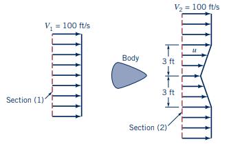
The results of a wind tunnel test to determine the drag on a body (see Fig. P5.65) are summarized below. The upstream [section (1)] velocity is uniform at \(100 \mathrm{ft} / \mathrm{s}\). The static pressures are given by \(p_{1}=p_{2}=14.7 \mathrm{psia}\). The downstream velocity distribution,
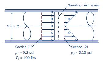
A variable mesh screen produces a linear and axisymmetric velocity profile as indicated in Fig. P5.66 in the airflow through a 2 -ft-diameter circular cross-sectional duct. The static pressures upstream and downstream of the screen are 0.2 and \(0.15 \mathrm{psi}\) and are uniformly distributed
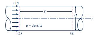
Consider unsteady flow in the constant diameter, horizontal pipe shown in Fig. P5.67. The velocity is uniform throughout the entire pipe, but it is a function of time: \(\mathbf{V}=u(t) \hat{\mathbf{i}}\). Use the \(x\) component of the unsteady momentum equation to determine the pressure
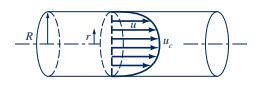
In a turbulent pipe flow that is fully developed, the axial velocity profile is,\[ u=u_{c}\left[1-\left(\frac{r}{R}\right)\right]^{1 / 7} \]as is illustrated in Fig. P5.68. Compare the axial direction momentum flowrate calculated with the average velocity, \(\bar{u}\), with the axial direction
Water from a garden hose is sprayed against your car to rinse dirt from it. Estimate the force that the water exerts on the car. List all assumptions and show calculations.
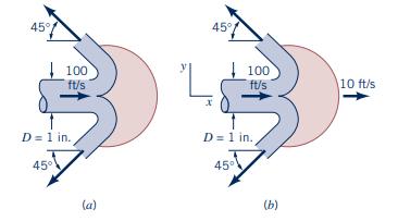
A Pelton wheel vane directs a horizontal, circular crosssectional jet of water symmetrically as indicated in Fig. P5.70 and Video V5.6. The jet leaves the nozzle with a velocity of \(100 \mathrm{ft} / \mathrm{s}\). Determine the \(x\)-direction component of anchoring force required to (a) hold the
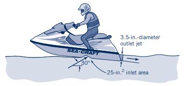
The thrust developed to propel the jet ski shown in Video V9.18 and Fig. P5.71 is a result of water pumped through the vehicle and exiting as a high-speed water jet. For the conditions shown in the figure, what flowrate is needed to produce a 300-1b thrust? Assume the inlet and outlet jets of water
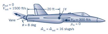
Thrust vector control is a technique that can be used to greatly improve the maneuverability of military fighter aircraft. It consists of using a set of vanes in the exit of a jet engine to deflect the exhaust gases as shown in Fig. P5.72.(a) Determine the pitching moment (the moment tending to
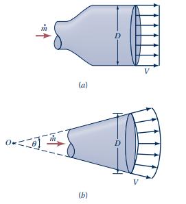
The exhaust gas from the rocket shown in Fig. P5.73a leaves the nozzle with a uniform velocity parallel to the \(x\) axis. The gas is assumed to be discharged from the nozzle as a free jet. (a) Show that the thrust that is developed is equal to \(ho A V^{2}\), where \(A=\pi D^{2} / 4\). (b) The
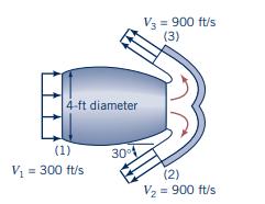
The Wide World of Fluids article titled "Where the Plume goes,". Air flows into the jet engine shown in Fig. P5.74 at a rate of 9 slugs/s and a speed of \(300 \mathrm{ft} / \mathrm{s}\). Upon landing, the engine exhaust exits through the reverse thrust mechanism with a speed of \(900 \mathrm{ft} /
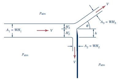
Figure P5.75 shows a sharp-edged splitter plate used to control the flow of a liquid jet \(W\) units wide by \(H_{1}\) units high. Write expressions for the deflection angle \(\theta\) and the force \(F\) of the jet on the splitter plate as a function of the fluid density \(ho, H_{1}, W, V\), and
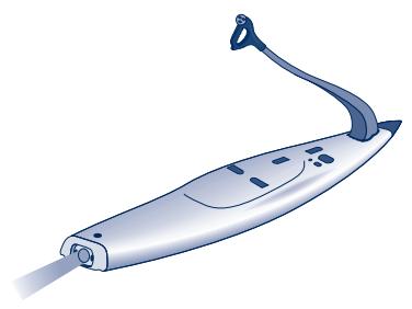
The Wide World of Fluids article titled "Motorized Surfboard,". The thrust to propel the powered surfboard shown in Fig. P5.76 is a result of water pumped through the board that exits as a high-speed 2.75-in.-diameter jet. Determine the flowrate and the velocity of the exiting jet if the thrust is
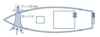
The Wide World of Fluids article titled "Bow Thrusters,".The bow thruster on the boat shown in Fig. P5.77 is used to turn the boat. The thruster produces a \(1-\mathrm{m}\)-diameter jet of water with a velocity of \(10 \mathrm{~m} / \mathrm{s}\). Determine the force produced by the thruster. Assume
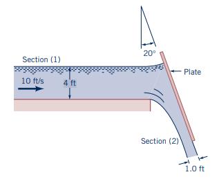
Water flows from a two-dimensional open channel and is diverted by an inclined plate as illustrated in Fig. P5.78. When the velocity at section (1) is \(10 \mathrm{ft} / \mathrm{s}\), what horizontal force (per unit width) is required to hold the plate in position? At section (1) the pressure
If a valve in a pipe is suddenly closed, a large pressure surge may develop. For example, when the electrically operated shutoff valve in a dishwasher closes quickly, the pipes supplying the dishwasher may rattle or "bang" because of this large pressure pulse. Explain the physical mechanism for
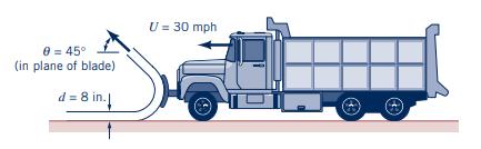
A snowplow mounted on a truck clears a path \(12 \mathrm{ft}\) through heavy wet snow, as shown in Figure P5.80. The snow is 8 in. deep and its density is \(10 \mathrm{lbm} / \mathrm{ft}^{3}\). The truck travels at \(30 \mathrm{mph}\). The snow is discharged from the plow at an angle of
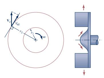
An incompressible fluid flows outward through a blower as indicated in Fig. P5.81. The shaft torque involved, \(T_{\text {shaft }}\), is estimated with the following relationship:\[ T_{\text {shaft }}=\dot{m} r_{2} V_{\theta 2} \]where \(\dot{m}=\) mass flowrate through the blower, \(r_{2}=\)
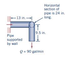
Water at \(60^{\circ} \mathrm{F}\) is flowing through the 2 -in. steel pipe shown in Fig. P5.82 at the rate of \(90 \mathrm{gal} / \mathrm{min}\). Determine the torque developed at the base where the pipe is supported. Neglect the pipe and water weights. Steady-state conditions apply.Figure P5.82
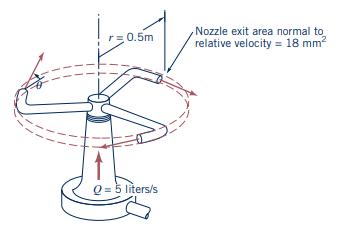
Five liters/s of water enter the rotor shown in Video V5.10 and Fig. P5.83 along the axis of rotation. The crosssectional area of each of the three nozzle exits normal to the relative velocity is \(18 \mathrm{~mm}^{2}\). How large is the resisting torque required to hold the rotor stationary? How
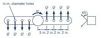
Figure P5.84 shows a simplified sketch of a dish-washer water supply manifold. Find the resisting torque for a water temperature of \(140^{\circ} \mathrm{F}\). \(Q=0.25 \mathrm{gal} / \mathrm{min}\) and \(\omega=3 \mathrm{rpm}\).Figure P5.84 1/4-in.-diameter holes 3 in. 2 in.2 in. 2 in. 45%
The hydraulic turbine shown in Fig. P5.85 has a \(10{ }^{\circ} \mathrm{C}\) water flow rate of \(36.4 \mathrm{~m}^{3} / \mathrm{s}\), an inlet radius \(R_{1}=1.0 \mathrm{~m}\), an outlet radius \(R_{2}=0.50 \mathrm{~m}\), a blade depth (perpendicular to paper) \(h=0.50 \mathrm{~m}\), and a
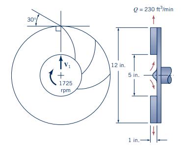
A fan (see Fig. P5.86) has a bladed rotor of 12 -in. outside diameter and 5-in. inside diameter and runs at \(1725 \mathrm{rpm}\). The width of each rotor blade is \(1 \mathrm{in}\). from blade inlet to outlet. The volume flowrate is steady at \(230 \mathrm{ft}^{3} / \mathrm{min}\), and the
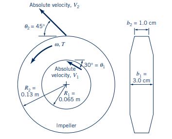
Calculate the torque required to drive the pump shown in Fig. P5.87 at \(30 \mathrm{~Hz}\) and to deliver \(20{ }^{\circ} \mathrm{C}\) water at \(3.0 \mathrm{~m}^{3} / \mathrm{min}\).Figure P5.87 Absolute velocity, V 8-45 00. T Absolute velocity, V 30 0 R = 0.13 m R = 0.065 m Impeller b = 1.0 cm b
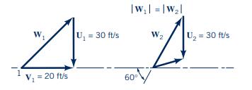
An axial flow turbomachine rotor involves the upstream (1) and downstream (2) velocity triangles shown in Fig. P5.88. Is this turbomachine a turbine or a fan? Sketch an appropriate blade section and determine energy transferred per unit mass of fluid.Figure P5.88 |W =|w2| W U = 30 ft/s W2 U = 30
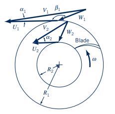
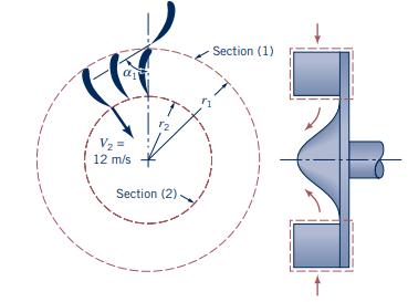
An inward flow radial turbine (see Fig. P5.89) involves a nozzle angle, \(\alpha_{1}\), of \(60^{\circ}\) and an inlet rotor tip speed, \(U_{1}\), of \(6 \mathrm{~m} / \mathrm{s}\). The ratio of rotor inlet to outlet diameters is 1.8. The absolute velocity leaving the rotor at section (2) is radial
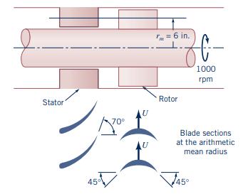
A sketch of the arithmetic mean radius blade sections of an axial-flow water turbine stage is shown in Fig. P5.90. The rotor speed is \(1000 \mathrm{rpm}\). (a) Sketch and label velocity triangles for the flow entering and leaving the rotor row. Use \(\mathbf{V}\) for absolute velocity,
Distinguish between shaft work and other kinds of work associated with a flowing fluid.
An incompressible fluid flows along a \(0.20-\mathrm{m}\)-diameter pipe with a uniform velocity of \(3 \mathrm{~m} / \mathrm{s}\). If the pressure drop between the upstream and downstream sections of the pipe is \(20 \mathrm{kPa}\), determine the power transferred to the fluid due to fluid normal
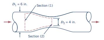
A horizontal Venturi flow meter consists of a convergingdiverging conduit as indicated in Fig. P5.93. The diameters of cross sections (1) and (2) are 6 and \(4 \mathrm{in}\). The velocity and static pressure are uniformly distributed at cross sections (1) and (2). Determine the volume flowrate
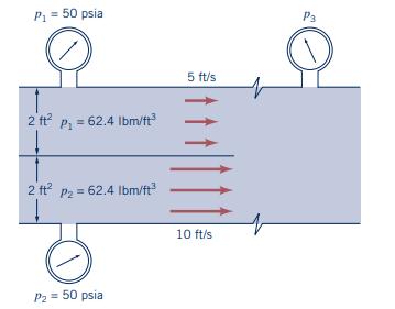
Figure P5.94 shows the mixing of two streams. The shear stress between each fluid and its adjacent walls is negligible. Why can't Bernoulli's equation be applied between points in stream 1 and the mixed stream or between points in stream 2 and the mixed stream?Figure P5.94 P = 50 psia 2 ft p = 62.4
Liquid water at \(40^{\circ} \mathrm{F}\) flows down a vertical, thermally insulated, 2 -in. steel pipe. The temperature change of the water is related to its internal energy change by\[ \tilde{u}_{2}-\tilde{u}_{1}=32.2 \mathrm{Btu} / \mathrm{slug} \cdot{ }^{\circ}
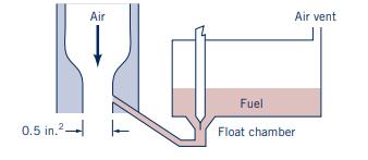
A simplified schematic drawing of the carburetor of a gasoline \((S=0.75)\) engine is shown in Fig. P5.96. The throat area is \(0.5 \mathrm{in.}^{2}\). The running engine draws air downward through the carburetor Venturi and maintains a throat pressure of 14.3 psia. The low throat pressure draws
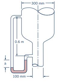
Oil \((S G=0.9)\) flows downward through a vertical pipe contraction as shown in Fig. P5.97. If the mercury manometer reading, \(h\), is \(100 \mathrm{~mm}\), determine the volume flowrate for frictionless flow. Is the actual flowrate more or less than the frictionless value? Explain.Figure P5.97
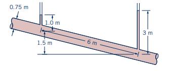
An incompressible liquid flows steadily along the pipe shown in Fig. P5.98. Determine the direction of flow and the head loss over the 6-m length of pipe.Figure P5.98 0.75 m 1.0 m 6 m 1.5 m 3 m
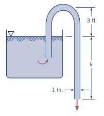
A siphon is used to draw water at \(70^{\circ} \mathrm{F}\) from a large container as indicated in Fig. P5.99. The inside diameter of the siphon line is \(1 \mathrm{in}\). and the pipe centerline rises \(3 \mathrm{ft}\) above the essentially constant water level in the tank. Show that by varying
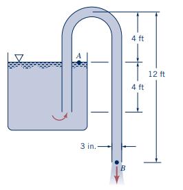
A water siphon having a constant inside diameter of 3 in. is arranged as shown in Fig. P5.100. If the friction loss between \(A\) and \(B\) is \(0.8 V^{2} / 2\), where \(V\) is the velocity of flow in the siphon, determine the flowrate involved.Figure P5.100 3 in.- B 4 ft 4 ft 12 ft
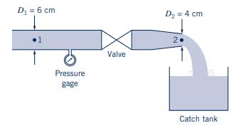
Figure P5.101 shows a test rig for evaluating the loss coefficient, \(\mathrm{K}\), for a valve. Mechanical energy losses in valves are modeled by the equation:\[ g h_{L}=\mathrm{K}\left(\frac{V^{2}}{2}\right) \]where \(g h_{L}\) is the mechanical energy loss and \(V\) is the flow velocity
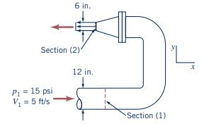
For the \(180^{\circ}\) elbow and nozzle flow shown in Fig. P5.102, determine the loss in available energy from section (1) to section (2). How much additional available energy is lost from section (2) to where the water comes to rest?Figure P5.102 6 in. Section (2) Pi = = 15 psi V = 5 ft/s 12 in.
An automobile engine will work best when the back pressure at the interface of the exhaust manifold and the engine block is minimized. Show how reduction of losses in the exhaust manifold, piping, and muffler will also reduce the back pressure. How could losses in the exhaust system be reduced?
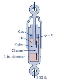
(See The Wide World of Fluids article titled "Smart Shocks," Section 5.3.3.) A 200-lb force applied to the end of the piston of the shock absorber shown in Fig. P5.104 causes the two ends of the shock absorber to move toward each other with a speed of \(5 \mathrm{ft} / \mathrm{s}\). Determine the
Based on flowrate and pressure rise information, estimate the power output of a human heart.
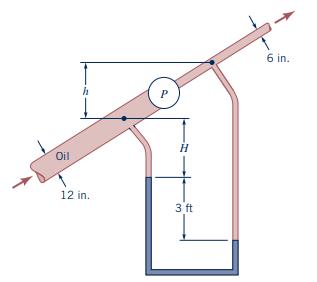
Oil \((S G=0.88)\) flows in an inclined pipe at a rate of \(5 \mathrm{ft}^{3} / \mathrm{s}\) as shown in Fig. P5.106. If the differential reading in the mercury manometer is \(3 \mathrm{ft}\), calculate the power that the pump supplies to the oil if head losses are negligible.Figure P5.106 Oil h H
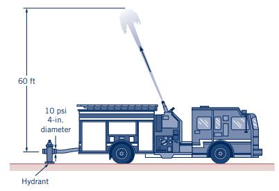
The pumper truck shown in Fig. P5.107 is to deliver \(1.5 \mathrm{ft}^{3} / \mathrm{s}\) to a maximum elevation of \(60 \mathrm{ft}\) above the hydrant. The pressure at the 4-in.-diameter outlet of the hydrant is \(10 \mathrm{psi}\). If head losses are negligibly small, determine the power that the
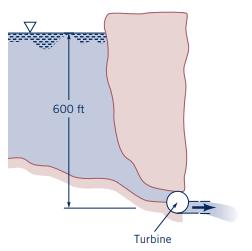
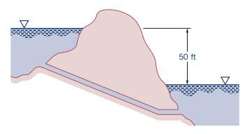
The hydroelectric turbine shown in Fig. P5.108 passesFigure P5.108 600 ft Turbine
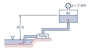
A pump is to move water from a lake into a large, pressurized tank as shown in Fig. P5.109 at a rate of \(1000 \mathrm{gal}\) in \(10 \mathrm{~min}\) or less. Will a pump that adds \(3 \mathrm{hp}\) to the water work for this purpose? Support your answer with appropriate calculations. Repeat the
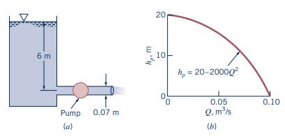
Water is pumped from the tank shown in Fig. P5.110a. The head loss is known to be \(1.2 V^{2} / 2 g\), where \(V\) is the average velocity in the pipe. According to the pump manufacturer, the relationship between the pump head and the flowrate is as shown in Fig. P5.110b: \(h_{p}=20-2000 Q^{2}\),
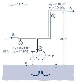
Water is pumped steadily through the apparatus shown in Fig. P5.111. The pipe area and gage pressure are shown for both outlet sections 1 and 2. Assume that the \(40^{\circ} \mathrm{F}\) water is frictionless and incompressible. Compute the horsepower input to the pump. The total volume flow rate
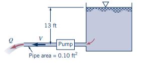
Water is pumped from the large tank shown in Fig. P5.112. The head loss is known to be equal to \(4 V^{2} / 2 g\) and the pump head is \(h_{p}=20-4 Q^{2}\), where \(h_{p}\) is in \(\mathrm{ft}\) when \(Q\) is in \(\mathrm{ft}^{3} / \mathrm{s}\). Determine the flowrate.Figure P5.112 13 ft Pump Pipe
Water flows by gravity from one lake to another as sketched in Fig. P5.113 at the steady rate of \(80 \mathrm{gpm}\). What is the loss in available energy associated with this flow? If this same amount of loss is associated with pumping the fluid from the lower lake to the higher one at the same
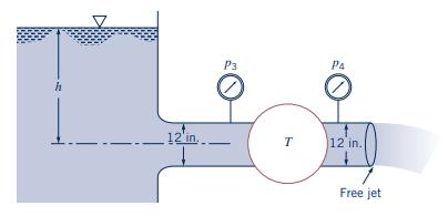
The turbine shown in Fig. P5.114 develops \(100 \mathrm{hp}\) when the flowrate of water is \(20 \mathrm{ft}^{3} / \mathrm{s}\). If all losses are negligible, determine(a) the elevation \(h\),(b) the pressure difference across the turbine, (c) the flowrate expected if the turbine were
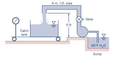
Figure P5.115 shows a pump testing setup. Water is drawn from a sump and pumped through a pipe containing a valve. The water is discharged into a catch tank sitting on a scale. During a test run, \(800 \mathrm{lb}\) of water is collected in the catch tank in \(15 \mathrm{~s}\). The pump power input
Water is to be moved from one large reservoir to another at a higher elevation as indicated in Fig. P5.116. The loss of available energy associated with \(2.5 \mathrm{ft}^{3} / \mathrm{s}\) being pumped from sections (1) to (2) is loss \(=61 \bar{V}^{2} / 2 \mathrm{ft}^{2} / \mathrm{s}^{2}\), where
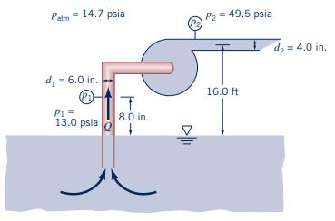
Determine the volume flow rate and minimum power input to the water pump in Fig. P5.117. Determine the actual power if the hydraulic efficiency is \(75 \%\) and losses in the motor and bearings are negligible.Figure P5.117 Palm = 14.7 psia P2 = 49.5 psia d = 4.0 in. d = 6.0 in. P = (P1) 13.0 psia T
A pump moves water horizontally at a rate of \(0.02 \mathrm{~m}^{3} / \mathrm{s}\). Upstream of the pump where the pipe diameter is \(90 \mathrm{~mm}\), the pressure is \(120 \mathrm{kPa}\). Downstream of the pump where the pipe diameter is \(30 \mathrm{~mm}\), the pressure is \(400 \mathrm{kPa}\).
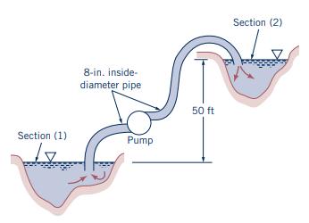
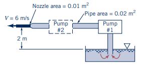
Water is to be pumped from the large tank shown in Fig. P5.119 with an exit velocity of \(6 \mathrm{~m} / \mathrm{s}\). It was determined that the original pump (pump 1) that supplies \(1 \mathrm{~kW}\) of power to the water did not produce the desired velocity. Hence, it is proposed that an
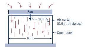
The Wide World of Fluids article titled "Curtain of Air,". The fan shown in Fig. P5.120 produces an air curtain to separate a loading dock from a cold storage room. The air curtain is a jet of air \(10 \mathrm{ft}\) wide, \(0.5 \mathrm{ft}\) thick moving with speed \(V=30 \mathrm{ft} /
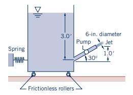
When the pump shown in Fig. P5.121 is stopped, there is no flow through the system and the spring force is zero. With the pump running, a 6 -in.-diameter jet leaves the pipe, and the spring force is \(420 \mathrm{lb}\). The water surface elevation in the tank is constant. Determine the water flow
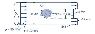
Air flows past an object in a pipe of 2-m diameter and exits as a free jet as shown in Fig. P5.122. The velocity and pressure upstream are uniform at \(10 \mathrm{~m} / \mathrm{s}\) and \(50 \mathrm{~N} / \mathrm{m}^{2}\), respectively. At the pipe exit the velocity is nonuniform as indicated. The
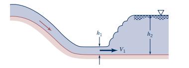
Near the downstream end of a river spillway, a hydraulic jump often forms, as illustrated in Fig. P5.123 and Video V10.11. The velocity of the channel flow is reduced abruptly across the jump. Using the conservation of mass and linear momentum principles, derive the following expression for
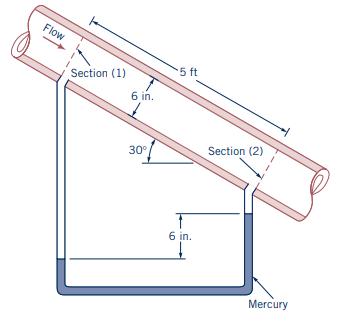
Water flows steadily down the inclined pipe as indicated in Fig P5.124. Determine the following: (a) the difference in pressure \(p_{1}-p_{2}\), (b) the loss between sections (1) and (2), (c) the net axial force exerted by the pipe wall on the flowing water between sections (1) and (2).Figure
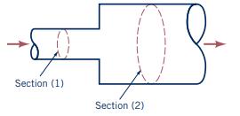
When fluid flows through an abrupt expansion as indicated in Fig. P5.125, the loss in available energy across the expansion, \(\operatorname{loss}_{\mathrm{ex}}\), is often expressed as\[ \operatorname{loss}_{\mathrm{ex}}=\left(1-\frac{A_{1}}{A_{2}}\right)^{2} \frac{V_{1}^{2}}{2} \]where
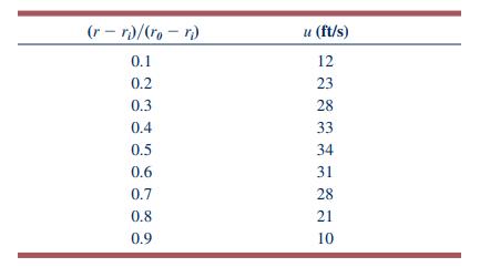
Water \(\left(60{ }^{\circ} \mathrm{F}\right)\) flows through an annular space formed by inserting a 1 -in.-radius solid cylinder into a 1.5-in.-radius tube. The following axial velocities were measured in the annular space.Assume that the no-slip condition \((u=0)\) exists at the solid boundaries.
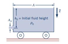
Find the acceleration of the cart shown in Fig. P5.127 as a function of the water height in the cart, which varies with time. The initial total mass is \(m_{0}\), and the fluid density is \(ho_{0}\). Assume frictionless bearings, a frictionless surface, constant fluid density, uniform velocity over
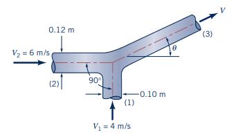
Two water jets collide and form one homogeneous jet as shown in Fig. P5.128. (a) Determine the speed, \(V\), and direction, \(\theta\), of the combined jet. (b) Determine the loss for a fluid particle flowing from (1) to (3), from (2) to (3). Gravity is negligible.Figure P5.128 V = 6 m/s 0.12 m (2)
Showing 600 - 700
of 2369
1
2
3
4
5
6
7
8
9
10
11
12
13
14
15
Last
Step by Step Answers