New Semester
Started
Get
50% OFF
Study Help!
--h --m --s
Claim Now
Question Answers
Textbooks
Find textbooks, questions and answers
Oops, something went wrong!
Change your search query and then try again
S
Books
FREE
Study Help
Expert Questions
Accounting
General Management
Mathematics
Finance
Organizational Behaviour
Law
Physics
Operating System
Management Leadership
Sociology
Programming
Marketing
Database
Computer Network
Economics
Textbooks Solutions
Accounting
Managerial Accounting
Management Leadership
Cost Accounting
Statistics
Business Law
Corporate Finance
Finance
Economics
Auditing
Tutors
Online Tutors
Find a Tutor
Hire a Tutor
Become a Tutor
AI Tutor
AI Study Planner
NEW
Sell Books
Search
Search
Sign In
Register
study help
engineering
engineering fluid mechanics
Engineering Fluid Mechanics 11th Edition Donald F. Elger, Barbara A. LeBret, Clayton T. Crowe, John A. Robertson - Solutions
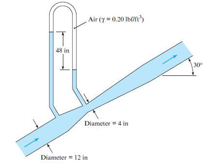
Estimate the rate of flow of water through the venturi meter shown. Air (y = 0.20 lbf/ft') 48 in 30° Diameter = 4 in Diameter = 12 in
Water flows through a venturi meter that has a 40 cm throat. The venturi meter is in a 70 cm pipe. What deflection will occur on a mercury-water manometer connected between the upstream and throat sections if the discharge is 0.75 m3/s? Assume T = 20°C.
What is the throat diameter required for a venturi meter in a 61 cm horizontal pipe carrying water with a discharge of 0.76 m3/s if the differential pressure between the throat and the upstream section is to be limited to 200 kPa at this discharge? For a first iteration, assume K = 1.02.
What is the main advantage of a venturi meter versus an orifice meter? The main disadvantage?
An orifice is to be designed to have a change in pressure of 48 kPa across it (measured with a differential-pressure transducer) for a discharge of 4.0 m3/s of water in a pipe 1.2 m in diameter. What diameter should the orifice have to yield the desired results?
What is the discharge of gasoline (SG = 0.68) in a 20 cm horizontal pipe if the differential pressure across a 10 cm orifice in the pipe is 100 kPa?
Determine the size of orifice required in a 15-cm pipe to measure 0.03 m3/s of water with a deflection of 1 m on a mercury-water manometer.
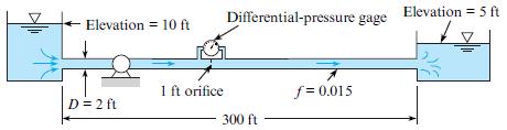
Water (T = 50°F) is pumped at a rate of 20 cfs through the system shown in the figure. What differential pressure will occur across the orifice? What power must the pump supply to the flow for the given conditions? Also, draw the HGL and the EGL for the system. Assume f = 0.015 for the pipe.
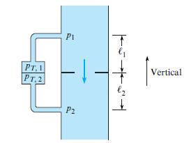
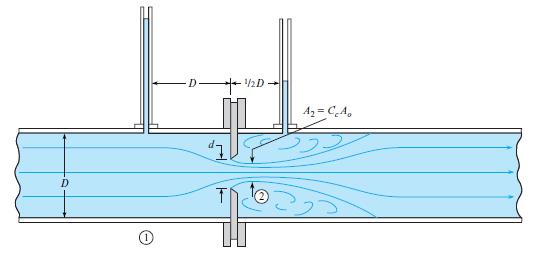
A pressure transducer is connected across an orifice as shown. The pressure at the upstream pressure tap is p1, and the pressure at the downstream tap is p2. The pressure at the transducer connected to the upstream tap is pT,1 and to the downstream pressure tap, pT,2. Show that the difference in
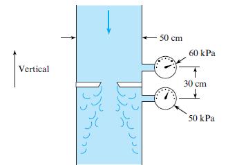
If water (20°C) is flowing through this 4.3 cm orifice, estimate the rate of flow. Assume flow coefficient K = 0.6. -50 cm 60 kPa Vertical 30 cm 50 kPa
A 15 cm plate orifice at the end of a 30 cm pipe is enlarged to 20 cm. With the same pressure drop across the orifice (approximately 50 kPa), what will be the percentage of increase in discharge?
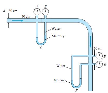
The 10 cm orifice in the horizontal 30 cm pipe shown is the same size as the orifice in the vertical pipe. The manometers are mercury-water manometers, and water (T = 20°C) is flowing in the system. The gages are Bourdon-tube gages. The flow, at a rate of 0.1 m3/s, is to the right in the
A 6 in. orifice is placed in a 10 in. pipe, and a mercury manometer is connected to either side of the orifice. If the flow rate of water (60°F) through this orifice is 4.5 cfs, what will be the manometer deflection?
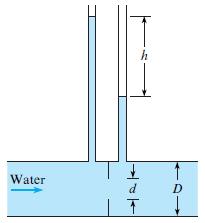
Determine the discharge of water (T = 60°F) through the orifice shown if h = 4 ft , D = 6 in., and d = 3 in. Water d D
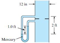
Determine the discharge of water through this 7 in. orifice that is installed in a 12 in. pipe. Assume T = 60°F and v = 1.22 × 10⁻⁵ ft 2/s. 12 in 2 ft 1.0 ft Mercury
Figure 13.14 in §13.2 shows a sharp-edged orifice. Note that the metal surface immediately downstream of the leading edge makes an acute angle with the metal of the upstream face of the orifice. Do you think the orifice would operate the same (have the same flow coefficient, K) if that angle were
A fluid jet discharging from a 10.2 cm orifice has a diameter of 8 cm at its vena contracta. What is the coefficient of contraction?
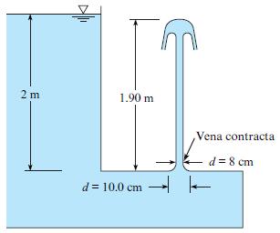
For the jet and orifice shown, determine Cv, Cc, and Cd. 2 m 1.90 m Vena contracta d = 8 cm d = 10.0 cm -
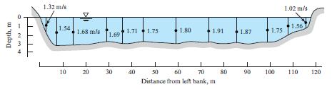
Theory and experimental verification indicate that the mean velocity along a vertical line in a wide stream is closely approximated by the velocity at 0.6 depth. If the indicated velocities at 0.6 depth in a river cross section are measured, what is the discharge in the river? 1.32 m/s 1.02 m/s
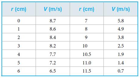
A velocity traverse in a 24 cm oil pipe yields the data in the table. What are the discharge, mean velocity, and ratio of maximum to mean velocity? Does the flow appear to be laminar or turbulent? r (cm) V (m/s) r (cm) V (m/s) 8.7 7 5.8 1 8.6 8 4.9 2 8.4 9 3.8 8.2 10 2.5 7.7 10.5 1.9 5 7.2 11.0 1.4
Water from a test apparatus is diverted into a calibrated volumetric tank for 6 min. If the volume of diverted water is measured to be 67 m3, what is the discharge in cubic meters per second, gallons per minute, and cubic feet per second?
Water from a pipe is diverted into a tank for 5 min. If the weight of diverted water is measured to be 10 kN, what is the discharge in cubic meters per second? Assume the water temperature is 20°C.
List five different instruments or approaches that engineers use to measure flow rate (discharge). For each instrument or approach, list two advantages and two disadvantages.
Classify the following devices as to whether they are used to measure velocity (V), pressure (P), or discharge (Q).a. Hot-wire anemometerb. Venturi meterc. Differential manometerd. Orifice metere. Stagnation tubef. Rotameterg. Ultrasonic flow meterh. Bourdon-tube gagei. Weirj. Laser-Doppler
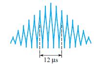
A laser-Doppler anemometer (LDA) system is being used to measure the velocity of air in a tube. The laser is an argon-ion laser with a wavelength of 4880 angstroms. The angle between the laser beams is 20°. The time interval is determined by measuring the time between five spikes, as shown, on the
On the Internet, locate technically sound resources relevant to the LDA. Skim these resources, and thena. Write down five findings that are relevant to engineering practice and interesting to you.b. Write down two questions about LDAs that are interesting and insightful.
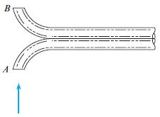
A velocity-measuring probe used frequently for measuring smokestack gas velocities is shown. The probe consists of two tubes bent away from and toward the flow direction and cut off on a plane normal to the flow direction, as shown. Assume the pressure coefficient is 1.0 at A and −0.4 at B. The
Without exceeding an error of 1%, what is the minimum water velocity that can be obtained using a 1.5 mm circular stagnation tube if the formulaV = √2Δpstag/ρ = √2ghstagis used for computing the velocity? Assume the water temperature is 20°C.
Without exceeding an error of 2.5%, what is the minimum air velocity that can be obtained using a 1 mm circular stagnation tube if the formula V = √2Δpstag/ρ = √2ghstag is used for computing the velocity? Assume standard atmospheric conditions.
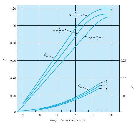
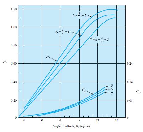
An ultralight airplane has a wing with an aspect ratio of 5 and with lift and drag coefficients corresponding to Fig. 11.24. The planform area of the wing is 200 ft2. The weight of the airplane and pilot is 400 lbf. The airplane flies at 50 ft/s in air with a density of 0.002 slugs/ft3. Find the
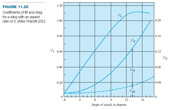
The wing loading on an airplane is defined as the aircraft weight divided by the wing area. An airplane with a wing loading of 2000 N/m2 has the aerodynamic characteristics given by Fig. 11.25. Under cruise conditions the lift coefficient is 0.3. If the wing area is 10 m2, find the drag force.In
An airplane wing having the characteristics shown in Fig. 11.24 is to be designed to lift 1800 lbf when the airplane is cruising at 200 ft /s with an angle of attack of 3°. If the chord length is to be 3.5 ft, what span of wing is required? Assume ρ = 0.0024 slugs/ft3.In figure 11.24 1.20 A== =
Apply the grid method to each situation that follows.a. Use Eq. (11.17) to predict the lift force in newtons for a spinning baseball. Use a coefficient of lift of CL = 1.2. The speed of the baseball is 90 mph. Calculate area using A = πr2, where the radius of a baseball is r = 1.45 in. Assume a
Estimate the energy in joules and kcal (food calories) that a runner supplies to overcome aerodynamic drag during a 10 km race. The runner runs a 6:30 pace (i.e., each mile takes 6 minutes and 30 seconds). The product of frontal area and coefficient of drag is CD A = 8 ft 2. (One “food
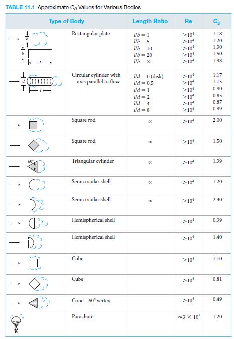
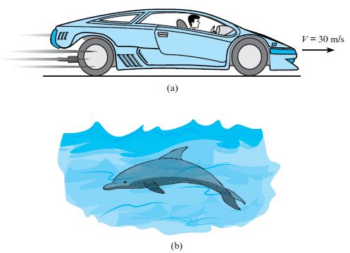
Consider trends from Table 11.1 and Fig. 11.9 in order to classify these statements as true or false:In table a. A value of CD = 0.35 for a sports car would be a reasonable estimate.b. A value of CD = 0.5 for a swimming dolphin would be a reasonable estimate.In figure 11.9 TABLE 11.1
Consider a large rock situated at the bottom of a river and acted on by a strong current. Estimate a typical speed of the current that will cause the rock to move downstream along the bottom of the river. List and justify all assumptions. Show all calculations and work in SI units. Use Table 11.1
A circular billboard with a diameter of 4 m is exposed to the wind. Estimate the total force exerted on the structure by a wind that has a direction normal to the structure and a speed of 20 m/s. Assume T = 10°C and p = 101 kPa absolute. Use Table 11.1 in §11.3.In table TABLE 11.1
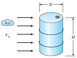
As shown, wind is blowing on a 55-gallon drum. Estimate the wind speed needed to tip the drum over. Work in SI units. The mass of the drum is 48 lbm, the diameter is 22.5 in., and the height is 34.5 in. Use Table 11.1 in §11.3.In Table 11.1 Air Vw H 10D
Estimate the drag of a thin square plate (3 m by 4 m) when it is towed through water (10°C). Assume a towing speed of about 5 m/s. Use Table 11.1 in §11.3. In Table 11.1a. The plate is oriented for minimum drag.b. The plate is oriented for maximum drag. TABLE 11.1 Approximate Cp Values for
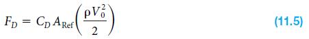
Apply the grid method to each situation that follows.a. Use Eq. (11.5) to predict the drag force in newtons for an automobile that is traveling at V = 60 mph on a summer day. Assume that the frontal area is 2 m2 and the coefficient of drag is CD = 0.4.b. Apply Eq. (11.5) to predict the speed in mph
Determine whether the following statements are true or false. a. Regarding CD, the primary dimensions are: M∙L/T2b. In the context of calculating the drag force for a sphere, the formula for projected area is: A = 4πr2
Determine whether the following statement is true or false: In general, the lift force is upward, and the drag force is horizontal with respect to gravity.
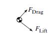
Determine whether the following statement is true or false: In general, the drag force and the lift force are perpendicular. FDrag Lift
Fill in the blanks for the following two statements:A. ___________ is associated with the viscous shear stress distribution.a. Form dragb. Friction dragB. ____________ is associated with the pressure distribution.a. Form dragb. Friction drag.
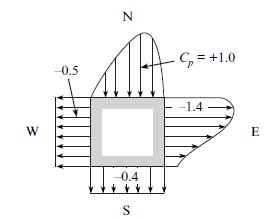
Flow is occurring past the square rod. The pressure coefficient values are as shown. From which direction do you think the flow is coming? (a) SW direction, (b) SE direction, (c) NW direction, or (d) NE direction. N C, = +1.0 0.5 -1.4 – 0.4
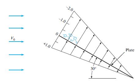
A hypothetical pressure coefficient variation over a long (length normal to the page) plate is shown. What is the coefficient of drag for the plate in this orientation and with the given pressure distribution? Assume that the reference area is the surface area (one side) of the plate. -2.0 -1.0
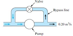
Frequently in the design of pump systems, a bypass line will be installed in parallel to the pump so that some of the fluid can recirculate as shown. The bypass valve then controls the flow rate in the system. Assume that the head-versus-discharge curve for the pump is given by hp = 100 – 100Q,
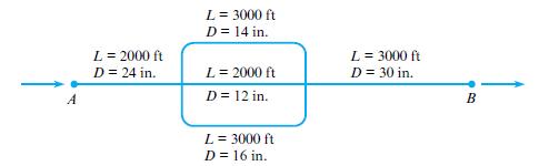
The pipes shown in the system are all concrete. With a flow of 25 cfs of water, find the head loss and the division of flow in the pipes from A to B. Assume f = 0.030 for all pipes. L= 3000 ft D = 14 in. L = 3000 ft D = 30 in. L = 2000 ft D = 24 in. L= 2000 ft D = 12 in. B L= 3000 ft D = 16 in.
Two pipes are connected in parallel. One pipe is twice the diameter of the other and four times as long. Assume that f in the larger pipe is 0.010 and f in the smaller one is 0.012. Determine the ratio of the discharges in the two pipes.
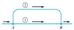
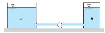
Pipes 1 and 2 are the same kind (cast-iron pipe), but pipe 2 is three times as long as pipe 1. They are the same diameter (1 ft). If the discharge of water in pipe 2 is 1.5 cfs, then what will be the discharge in pipe 1? Assume the same value of f in both pipes. 2 1. A B
In the parallel system shown, pipe 1 is 1200 m long and is 50 cm in diameter. Pipe 2 is 1500 m long and 35 cm in diameter. Assume f is the same in both pipes. What is the division of the flow of water at 10°C if the flow rate will be 1.2 m3/s?
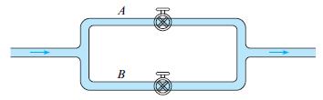
A flow is divided into two branches as shown. A gate valve, half open, is installed in line A, and a globe valve, fully open, is installed in line B. The head loss due to friction in each branch is negligible compared with the head loss across the valves. Find the ratio of the velocity in line A to
A pipe system consists of a gate valve, wide-open (Kv = 0.2), in line A and a globe valve, wide-open (Kv = 10), in line B. The cross-sectional area of pipe A is half of the cross-sectional area of pipe B. The head loss due to the junction, elbows, and pipe friction are negligible compared with the
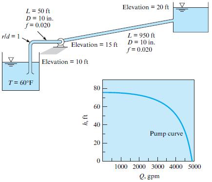
A pump that has the characteristic curve shown in the accompanying graph is to be installed as shown. What will be the discharge of water in the system? Elevation = 20 ft L = 50 ft D = 10 in. f = 0.020 rld = 1 L = 950 ft D = 10 in. f = 0.020 Elevation = 15 ft Elevation = 10 ft T= 60°F 80 60 40
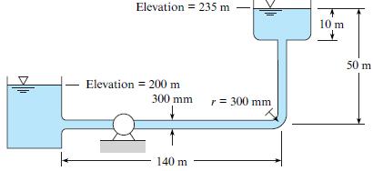
If the pump for Fig. 10.20b is installed in the system of Prob. 10.90, what will be the rate of discharge of water from the lower tank to the upper one?Data from Prob. 10.90,What power must be supplied by the pump to the flow if water (T = 20°C) is pumped through the 300-mm steel pipe from the
What power must be supplied by the pump to the flow if water (T = 20°C) is pumped through the 300-mm steel pipe from the lower tank to the upper one at a rate of 0.75 m3/s? Elevation = 235 m 10 m 50 m Elevation = 200 m 300 mm r = 300 mm 140 m
Air (20°C) flows with a speed of 10 m/s through a horizontal rectangular air-conditioning duct. The duct is 20 m long and has a cross section of 4 by 10 in. (102 by 254 mm). Calculate (a) The pressure drop in inches of water and (b) The power in watts needed to overcome head loss. Assume
A cold-air duct 120 cm by 15 cm in cross section is 100 m long and made of galvanized iron. This duct is to carry air at a rate of 6 m3/s at a temperature of 15°C and atmospheric pressure. What is the power loss in the duct?
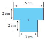
The cross section of an air duct has the dimensions shown in the sketch. Find the hydraulic diameter in units of cm. Choose the closest answer (cm): (a) 0.9, (b) 3.0, (c) 3.2, (d) 3.6, (e) 4.1. 5 сm 2 cm 2 cm 3 ст
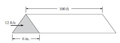
Air at 60°F and atmospheric pressure flows in a horizontal duct with a cross section corresponding to an equilateral triangle (all sides equal). The duct is 100 ft long, and the dimension of a side is 6 in. The duct is constructed of galvanized iron (ks = 0.0005 ft ). The mean velocity in the duct
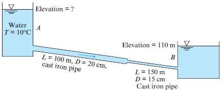
If the water surface elevation in reservoir B is 110 m, what must be the water surface elevation in reservoir A if a flow of 0.03 m3/s is to occur in the cast iron pipe? Draw the HGL and the EGL, including relative slopes and changes in slope. Elevation = ? Water A T= 10°C Elevation = 110 m B L=
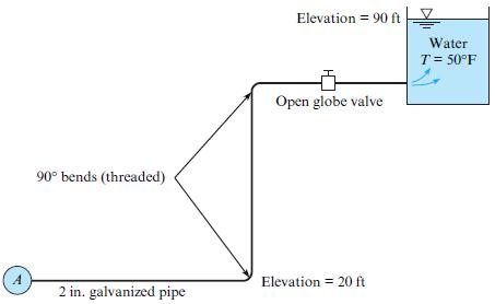
The steel pipe shown carries water from the main pipe A to he reservoir and is 2 in. in diameter and 300 ft long. What must be the pressure in pipe A to provide a flow of 70 gpm? Elevation = 90 ft Water T= 50°F Open globe valve 90° bends (threaded) A Elevation = 20 ft 2 in. galvanized pipe
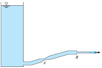
Liquid discharges from a tank through the piping system shown. There is a venturi section at A and a sudden contraction at B. The liquid discharges to the atmosphere. Sketch the energy and hydraulic grade lines. Where might cavitation occur? B A
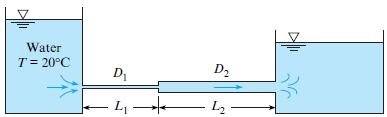
Both pipes in the system shown have an equivalent sand roughness ks of 0.10 mm and a flow rate of 0.1 m3/s, with D1 = 12 cm, L1 = 60 m, D2 = 24 cm, and L2 = 120 m. Determine the difference in the water-surface elevation between the two reservoirs. Water T= 20°C D1 D2 - 4 L2
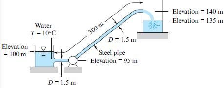
Water is pumped at a rate of 32 m3/s from the reservoir and out through the pipe, which has a diameter of 1.50 m. What power must be supplied to the water to effect this discharge? Elevation = 140 m Water Elevation = 135 m T = 10°C 300 m D = 1.5 m Elevation = 100 m Steel pipe Elevation = 95 m D =
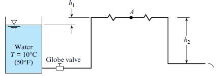
The 12 cm galvanized steel pipe shown is 800 m long and discharges water into the atmosphere. The pipeline has an open globe valve and four threaded elbows; h1 = 3 m and h2 = 15 m. What is the discharge, and what is the pressure at A, the midpoint of the line? A Water T= 10°C (50°F) Globe valve
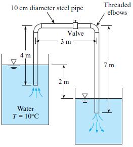
Find the loss coefficient Kv of the partially closed valve that is required to reduce the discharge to 50% of the flow with the valve wide-open as shown. Threaded elbows 10 cm diameter steel pipe Valve 3 m 4 m 7 m 2 m Water T = 10°C
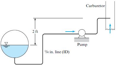
Gasoline (T = 50°F) is pumped from the gas tank of an automobile to the carburetor through a 1/4-in. fuel line of drawn tubing 10 ft long. The line has five 90° smooth bends with an r/d of 6. The gasoline discharges through a 1/32-in. jet in the carburetor to a pressure of 14 psia. The pressure
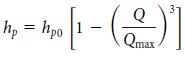
A heat exchanger consists of 15 m of copper tubing with an internal diameter of 15 mm. There are 14 return elbows in the system with a loss coefficient of 2.2 for each elbow. The pump in the system has a pump curve given bywhere hp0 is head provided by the pump at zero discharge and Qmax is 10–3
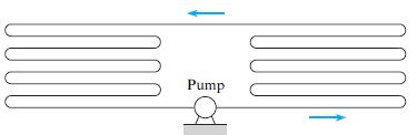
A heat exchanger consists of a closed system with a series of parallel tubes connected by 180° elbows as shown in the figure. There are a total of 14 return elbows. The pipe diameter is 2 cm, and the total pipe length is 10 m. The head loss coefficient for each return elbow is 2.2. The tube is
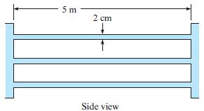
A heat exchanger is being designed as a component of a geothermal power system in which heat is transferred from the geothermal brine to a “clean” fluid in a closed-loop power cycle. The heat exchanger, a shell-and-tube type, consists of 100 galvanized iron tubes 2 cm in diameter and 5 m long,
An engineer is making an estimate of hydroelectric power for a home owner. This owner has a small stream (Q = 2 cfs, T = 40 °F) that is located at an elevation H = 34 ft above the owner’s residence. The owner is proposing to divert the stream and operate a water turbine connected to an electric
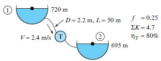
Water flows through a turbine. Calculate the power (MW) transmitted by the output shaft of the turbine. The water density is 1000 kg/m3. The elevation of the upper reservoir surface is 720 m and that of the lower reservoir is 695 m. The pipeline diameter is 2.2 m, the total length is 50 m, and the
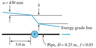
Water is flowing through a gate valve (Kv = 0.2). Calculate the value of b in units of mm. The pipe is horizontal. The flow is steady and fully developed. Over a 3-meter pipe length upstream of the valve, the EGL drops by a = 430 mm. The pipe ID is 0.25 m and the friction factor in the pipe is
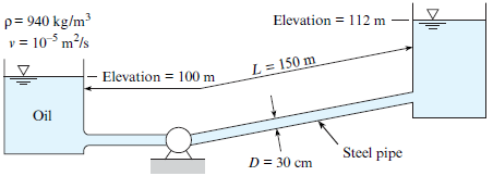
What power must the pump supply to the system to pump the oil from the lower reservoir to the upper reservoir at a rate of 0.3 m3/s? Sketch the HGL and the EGL for the system.
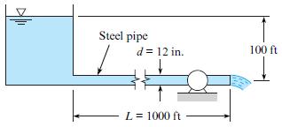
A water turbine is connected to a reservoir as shown. The flow rate in this system is 4 cfs. What power can be delivered by the turbine if its efficiency is 90%? Assume a temperature of 70°F. Steel pipe d= 12 in. 100 ft L= 1000 ft
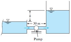
A pump is used to fill a tank from a reservoir as shown. The head provided by the pump is given by hp = h0(l–Q2/Q2 max)) where h0 is 50 meters, Q is the discharge through the pump, and Qmax is 2 m3/s. Assume f = 0.018 and the pipe diameter is 90 cm. Initially the water level in the tank is
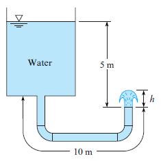
A tank and piping system are shown. The galvanized pipe diameter is 3 cm, and the total length of pipe is 10 m. The two 90° elbows are threaded fittings. The vertical distance from the water surface to the pipe outlet is 5 m. Find (a) The exit velocity of the water and (b) The
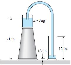
Water will be siphoned through a 3/16-in.-diameter, 50 in. long Tygon tube from a jug on an upside-down wastebasket into a graduated cylinder as shown. The initial level of the water in the jug is 21 in. above the tabletop. The graduated cylinder is a 500 mL cylinder, and the water surface in the
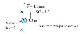
A liquid flows upward through a valve situated in a vertical pipe. Calculate the differential pressure (kPa) between points A and B. The mean velocity of the flow is 4.1 m/s. The specific gravity of the liquid is 1.2. The pipe has constant diameter. The valve has a minor loss coefficient of 4.0.
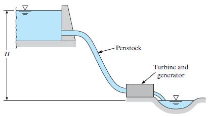
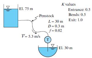
Water flows out of a reservoir, through a penstock, and then through a turbine. Calculate the total head loss in units of meters. The mean velocity is 5.3 m/s. The friction factor is 0.02. The total penstock length is 30 m and the diameter is 0.3 m. There are three minor loss coefficients: 0.5 for
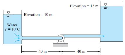
If the flow of 0.10 m3/s of water is to be maintained in the system shown, what power must be added to the water by the pump? The pipe is made of steel and is 15 cm in diameter. Elevation = 13 m Elevation = 10 Water T= 10°C 40 m 40 m
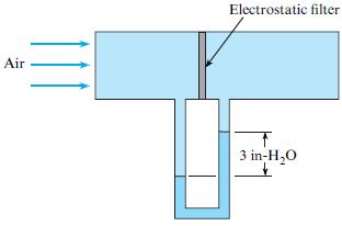
The sketch shows a test of an electrostatic air filter. The pressure drop for the filter is 3 inches of water when the airspeed is 9 m/s. What is the minor loss coefficient for the filter? Assume air properties at 20°C. Electrostatic filter Air 3 in-H,0
Use Table 10.5 (§10.8) to select loss coefficients, K, for the following transitions and fittings.a. A threaded pipe 90° elbowb. A 90° smooth bend with r/d = 2c. A pipe entrance with r/d of 0.3d. An abrupt contraction, with θ = 180°, and D2/D1 = 0.60e. A gate valve, wide open
A pipeline is to be designed to carry crude oil (SG = 0.93, ν = 10–5 m2/s) with a discharge of 0.10 m3/s and a head loss per kilometer of 50 m. What diameter of steel pipe is needed? What power output from a pump is required to maintain this flow? Available pipe diameters are 20, 22, and 24 cm.
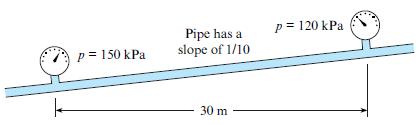
A fluid with ν = 10–6 m2/s and ρ = 800 kg/m3 flows through the 8 cm galvanized iron pipe. Estimate the flow rate for the conditions shown in the figure. p = 120 kPa Pipe has a slope of 1/10 p = 150 kPa 30 m
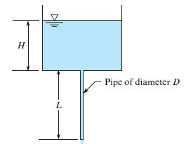
As shown, water (15°C) is draining from a tank through a galvanized iron pipe. The pipe length is L = 2 m, the tank depth is H = 1 m, and the pipe is a 0.5 inch NPS schedule 40. Calculate the velocity in the pipe. Neglect component head loss. H Pipe of diameter D L
As shown, water (70°F) is draining from a tank through a galvanized iron pipe. The pipe length is L = 10 ft , the tank depth is H = 4 ft , and the pipe is 1 in. NPS schedule 40. Calculate the velocity in the pipe and the flow rate. Neglect component head loss.
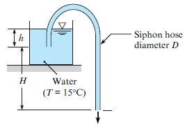
A plastic siphon hose of length 7 m is used to drain water (15°C) out of a tank. For a flow rate of 1.5 L/s, what hose diameter is needed? Use H = 5 m and h = 0.5 m. Assume all head loss occurs in the tube. Siphon hose diameter D h Water (T = 15°C)
A plastic siphon hose with D = 1.2 cm and L = 5.5 m is used to drain water (15°C) out a tank. Calculate the velocity in the tube for the two situations given below. Use H = 3 m and h = 1 m. a. Assume the Bernoulli equation applies (neglect all head loss).b. Assume the component head loss is
Water (60°F) is pumped from a reservoir to a large, pressurized tank as shown. The steel pipe is 4 in. in diameter and 300 ft long. The discharge is 1 cfs. The initial water levels in the tanks are the same, but the pressure in tank B is 10 psig, and tank A is open to the atmosphere. The pump
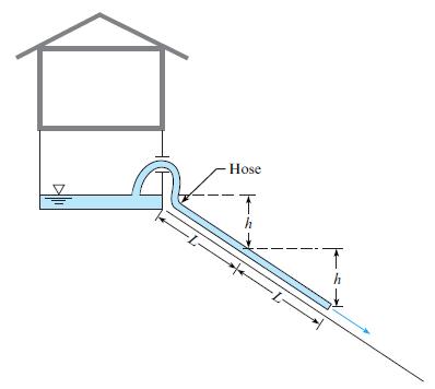
The house shown is flooded by a broken waterline. The owners siphon water out of the basement window and down the hill, with one hose, of length L, and thus an elevation difference of h to drive the siphon. Water drains from the siphon, but too slowly for the desperate home owners. They reason that
Water is pumped through a vertical 10 cm new steel pipe to an elevated tank on the roof of a building. The pressure on the discharge side of the pump is 1.6 MPa. What pressure can be expected at a point in the pipe 110 m above the pump when the flow is 0.02 m3/s? Assume T = 20°C.
Air flows in a 1 in. smooth tube at a rate of 30 cfm. If T = 80°F and p = 15 psia, what is the pressure drop per foot of length of tube?
Air flows in a 3-cm smooth tube at a rate of 0.015 m3/s. If T = 20°C and p = 110 kPa absolute, what is the pressure drop per meter of length of tube?
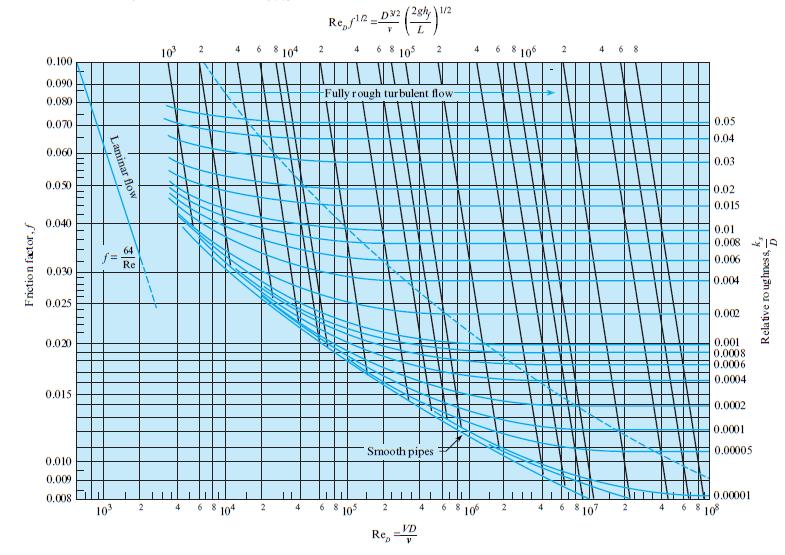
In a 4.2 in. uncoated cast iron pipe, 0.08 cfs of water flows at 60°F. Determine f from Fig. 10.14.In figure 10.14 D2 (2gh, 1/2 Re, rle=- 10 104 6 8 10 4 10 2. 0.100 0.090 Fully rough turbulent flow- 0.080 0.070 0.05 0.04 0.060 0.03 0.050 0.02 0.015 0.040 0.01 0.008 64 0.006 Re 0.030 0.004 0.025
Water (10°C) flows with a speed of 2 m/s through a horizontal run of PVC pipe. The length of the pipe is 50 m, and the pipe is schedule 40 with a nominal diameter of 2.5 inches. Calculate (a) The pressure drop in kilopascals, (b) The head loss in meters, and (c) The power in watts
Water (50°F) flows with a speed of 5 ft /s through a horizontal run of PVC pipe. The length of the pipe is 100 ft , and the pipe is schedule 40 with a nominal diameter of 2.5 inches. Calculate (a) The pressure drop in psi, (b) The head loss in feet, and (c) The power in horsepower
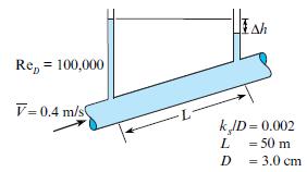
A fluid flows through a pipe. Calculate the drop in piezometer level (Δh) in units of cm. The flow is steady and fully developed. The fluid is Newtonian. The mean velocity is 0.4 m/s. The Reynolds number is 100,000. The relative roughness is 0.002. The length between piezometers is 50 m and the
You have the values for (a) The Darcy friction factor and(b) The relative roughness. You have a Moody diagram. Determine whether the following statement is true or false: You can find the value of Reynolds number by using the Moody diagram.
Showing 1300 - 1400
of 2369
First
7
8
9
10
11
12
13
14
15
16
17
18
19
20
21
Last
Step by Step Answers