New Semester
Started
Get
50% OFF
Study Help!
--h --m --s
Claim Now
Question Answers
Textbooks
Find textbooks, questions and answers
Oops, something went wrong!
Change your search query and then try again
S
Books
FREE
Study Help
Expert Questions
Accounting
General Management
Mathematics
Finance
Organizational Behaviour
Law
Physics
Operating System
Management Leadership
Sociology
Programming
Marketing
Database
Computer Network
Economics
Textbooks Solutions
Accounting
Managerial Accounting
Management Leadership
Cost Accounting
Statistics
Business Law
Corporate Finance
Finance
Economics
Auditing
Tutors
Online Tutors
Find a Tutor
Hire a Tutor
Become a Tutor
AI Tutor
AI Study Planner
NEW
Sell Books
Search
Search
Sign In
Register
study help
engineering
introduction mechanical engineering
Mechanical Vibrations Theory And Applications 1st Edition S. GRAHAM KELLY - Solutions
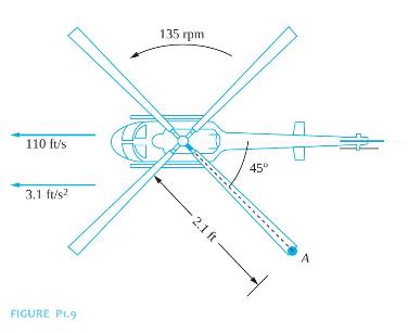
The helicopter of Figure P1.9 has a horizontal speed of \(110 \mathrm{ft} / \mathrm{s}\) and a horizontal acceleration of \(3.1 \mathrm{ft} / \mathrm{s}^{2}\). The main blades rotate at a constant speed of \(135 \mathrm{rpm}\). At the instant shown, determine the velocity and acceleration of
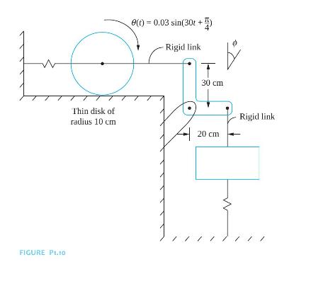
For the system shown in Figure P1.10, the angular displacement of the thin disk is given by \(\theta(t)=0.03 \sin \left(30 t+\frac{\pi}{4}\right)\) rad. The disk rolls without slipping on the surface. Determine the following as functions of time.(a) The acceleration of the center of the disk.(b)
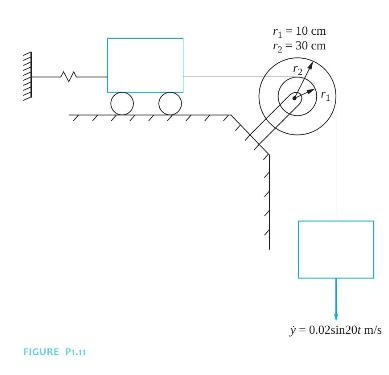
The velocity of the block of the system of Figure P1.11 is \(\dot{y}=0.02 \sin 20 t \mathrm{~m} / \mathrm{s}\) downward.(a) What is the clockwise angular displacement of the pulley?(b) What is the displacement of the cart? r = 10 cm 2-30 12 FIGURE P1.11 - 0.02sin20t m/s
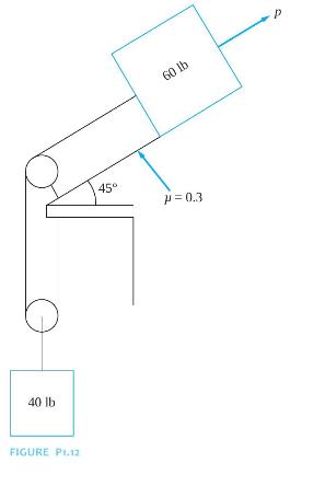
A 60-lb block is connected by an inextensible cable through the pulley to the fixed surface, as shown in Figure P1.12. A \(40 \mathrm{lb}\) weight is attached to the pulley, which is free to move vertically. A force of magnitude \(P=100\left(1+e^{-t}\right) \mathrm{lb}\) tows the block. The system
Repeat Problem 1.8 for a force of \(P=100 t \mathrm{~N}\).Data From Problem 1.8:The contour of a bumpy road is approximated by\[ y(x)=0.03 \sin (0.125 x) \mathrm{m} \]
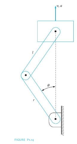
Figure P1.14 shows a schematic diagram of a one-cylinder reciprocating onecylinder engine. If at the instant of time shown the piston has a velocity \(v\) and an acceleration \(a\), determine (a) the angular velocity of the crank and (b) the angular acceleration of the crank in terms of \(v, a\),
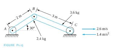
Determine the reactions at \(A\) for the two-link mechanism of Figure P1.15. The roller at \(C\) rolls on a frictionless surface. A - 2 m B FIGURE P1.15 30 2.4 kg -3m 3.6 kg 2.6 m/s -1.4 m/s
Determine the angular acceleration of each of the disks in Figure P1.16. 20 kg 60 cm. 4 kgm 60 cm FIGURE P1.16 (a) 30 kg 180 N (b) 270 N 4 kg-m2
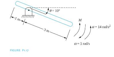
Determine the reactions at the pin support and the applied moment if the bar of Figure P1.17 has a mass of \(50 \mathrm{~g}\). FIGURE P1.17 0-10 M -14 rad/s 3 m 0 = 5 radis
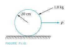
The disk of Figure P1.18 rolls without slipping. Assume if \(P=18 \mathrm{~N}\).(a) Determine the acceleration of the mass center of the disk.(b) Determine the angular acceleration of the disk. 20 cm 1.8 kg FIGURE P1.18 777 P
The coefficient of friction between the disk of Figure P1.18 and the surface is 0.12 . What is the largest force that can be applied such that the disk rolls without slipping? 20 cm 1.8 kg FIGURE P1.18 777 P
The coefficient of friction between the disk of Figure P1.18 and the surface is 0.12 . If \(P=22 \mathrm{~N}\), what are the following?(a) Acceleration of the mass center.(b) Angular acceleration of the disk. 20 cm 1.8 kg FIGURE P1.18 777 P
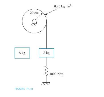
The \(3 \mathrm{~kg}\) block of Figure P1.21 is displaced \(10 \mathrm{~mm}\) downward and then released from rest.(a) What is the maximum velocity attained by the \(3-\mathrm{kg}\) block?(b) What is the maximum angular velocity attained by the disk? 20 cm 0.25 kg m 5 kg 3 kg FIGURE P1.21 4000 N/m
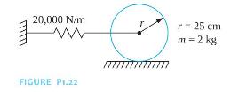
The center of the thin disk of Figure P1.22 is displaced \(15 \mathrm{~mm}\) and released. What is the maximum velocity attained by the disk, assuming no slipping between the disk and the surface? 20,000 N/m FIGURE P1.22 r = 25 cm m = 2 kg
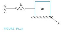
The block of Figure P1.23 is given a displacement \(\delta\) and then released.(a) What is the minimum value of \(\delta\) such that motion ensues?(b) What is the minimum value of \(\delta\) such that the block returns to its equilibrium position without stopping? k FIGURE P1.23 E
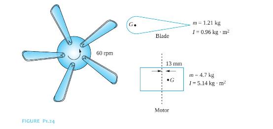
The five-blade ceiling fan of Figure P1.24 operates at \(60 \mathrm{rpm}\). The distance between the mass center of a blade and the axis of rotation is \(0.35 \mathrm{~m}\). What is its total kinetic energy? G. Blade m-1.21 kg I-0.96 kg m 60 rpm 13 mm G m = 4.7 kg 1-5.14 kg m FIGURE P1.24 Motor
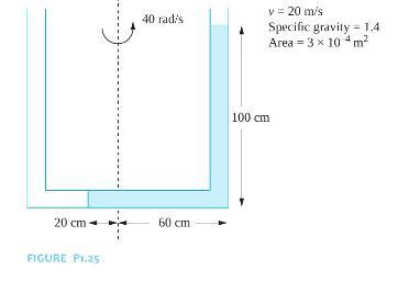
The U-tube manometer shown in Figure P1.25 rotates about axis \(A-A\) at a speed of \(40 \mathrm{rad} / \mathrm{s}\). At the instant shown, the column of liquid moves with a speed of \(20 \mathrm{~m} / \mathrm{s}\) relative to the manometer. Calculate the total kinetic energy of the column of
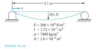
The displacement function for the simply supported beam of Figure P1.26 is\[ y(x, t)=c \sin \left(\frac{\pi x}{L}\right) \cos \left(\pi^{2} \sqrt{\frac{E I}{ho A L^{4}}} t\right) \]where \(c=0.003 \mathrm{~m}\) and \(t\) is in seconds. Determine the kinetic energy of the beam. x 3.1 m FIGURE
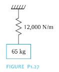
The block of Figure P1.27 is displaced \(1.5 \mathrm{~cm}\) from equilibrium and released.(a) What is the maximum velocity attained by the block?(b) What is the acceleration of the block immediately after it is released? 12,000 N/m 65 kg FIGURE P1.27
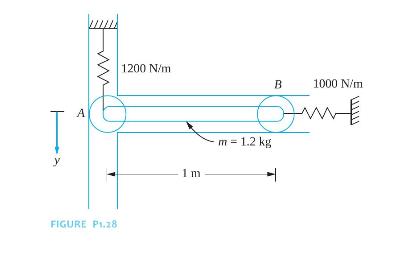
The slender rod of Figure P1.28 is released from the horizontal position when the spring attached at \(A\) is stretched \(10 \mathrm{~mm}\) and the spring attached at \(B\) is unstretched.(a) What is the acceleration of the bar immediately after it is released?(b) What is the maximum angular
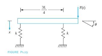
Let \(x\) be the displacement of the left end of the bar of the system in Figure P1.29. Let \(\theta\) represent the clockwise angular rotation of the bar.(a) Express the kinetic energy of the system at an arbitrary instant in terms of \(\dot{x}\) and \(\dot{\theta}\).(b) Express the potential
Repeat Problem 1.29 using as coordinates \(x_{1}\), which is the displacement of the mass center, and \(x_{2}\), which is the displacement of the point of attachment of the spring that is a distance \(3 L / 4\) from the left end.Data From Problem 1.29:Let \(x\) be the displacement of the left end
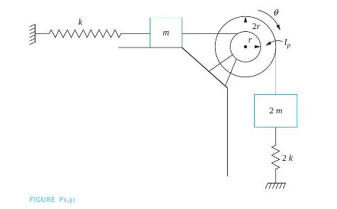
Let \(\theta\) represent the clockwise angular displacement of the pulley of the system in Figure P1.31 from the system's equilibrium position.(a) Express the potential energy of the system at an arbitrary instant in terms of \(\theta\).(b) Express the kinetic energy of the system at an arbitrary
A 20 ton railroad car is coupled to a 15 ton car by moving the 20 ton car at \(5 \mathrm{mph}\) toward the stationary 15 ton car.(a) What is the resulting speed of the two-car coupling?(b) What would the resulting speed be if the 15 ton car is moving at \(5 \mathrm{mph}\) toward a stationary 20 ton
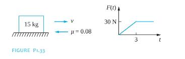
The \(15 \mathrm{~kg}\) block of Figure P1.33 is moving with a velocity of \(3 \mathrm{~m} / \mathrm{s}\) at \(t=0\) when the force \(F(t)\) is applied to the block.(a) Determine the velocity of the block at \(t=2 \mathrm{~s}\).(b) Determine the velocity of the block at \(t=4 \mathrm{~s}\).(c)
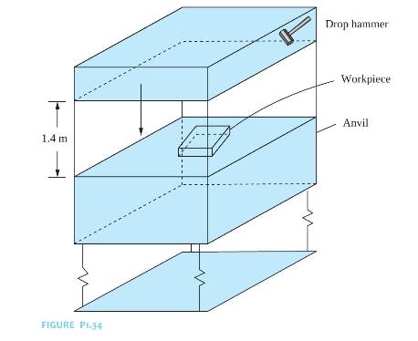
A \(400 \mathrm{~kg}\) forging hammer is mounted on four identical springs, each of stiffness \(k=4200 \mathrm{~N} / \mathrm{m}\). During the forging process, a \(110 \mathrm{~kg}\) hammer, which is part of the machine, is dropped from a height of \(1.4 \mathrm{~m}\) onto an anvil, as shown in
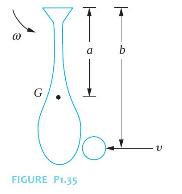
The motion of a baseball bat in a ballplayer's hands is approximated as a rigidbody motion about an axis through the player's hands, as shown in Figure P1.35. The bat has a centroidal moment of inertia \(I\). The player's "bat speed" is \(\omega\), and the velocity of the pitched ball is \(v\).
A playground ride has a centroidal moment of inertia of \(17 \mathrm{slug} \cdot \mathrm{ft}^{2}\). Three children of weights \(50 \mathrm{lb}, 50 \mathrm{lb}\), and \(55 \mathrm{lb}\) are on the ride, which is rotating at \(60 \mathrm{rpm}\). The children are \(30 \mathrm{in}\). from the center of
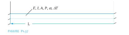
The natural frequencies of a thermally loaded fixed-fixed beam (Figure P1.37) are a function of the material properties of the beam, including:\(E\), the elastic modulus of the beam\(ho\), the mass density of the beam\(\alpha\), the coefficient of thermal expansion The geometric properties of the
The drag force \(F\) on a circular cylinder due to vortex shedding is a function of\(U\), the velocity of the flow\(\mu\), the dynamic viscosity of the fluid\(ho\), the mass density of the fluid\(L\), the length of the cylinder\(D\), the diameter of the cylinder Present different problems that are
The principal normal stress \(\sigma\) due to forcing of a beam with a concentrated harmonic excitation is a function of\(F_{0}\), the amplitude of loading\(\omega\), the frequency of the loading\(E\), the elastic modulus of the beam\(ho\), the mass density of the beam\(A\), the beam's
A MEMS system is undergoing simple harmonic motion according to\[ x(t)=\left[3.1 \sin \left(2 \times 10^{5} t+0.48\right)+4.8 \cos \left(2 \times 10^{5} t+1.74\right)\right] \mu \mathrm{m} \](a) What is the period of motion?(b) What is the frequency of motion in \(\mathrm{Hz}\) ?(c) What is the
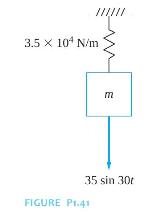
The force that causes simple harmonic motion in the mass-spring system of Figure P1.41 is \(F(t)=35 \sin 30 t \mathrm{~N}\). The resulting displacement of the mass is \(x(t)=0.002 \sin (30 t-\pi) \mathrm{m}\).(a) What is the period of the motion?(b) The amplitude of displacement is
The displacement vector of a particle is\(\mathbf{r}(t)=[2 \sin 20 t \mathbf{i}+3 \cos 20 t \mathbf{j}] \mathrm{mm}\)(a) Describe the trajectory of the particle.(b) How long does it take the particle to make one circuit around the path?
The differential equation governing the free vibrations of a sliding mass-spring and viscous-damper system (without friction) is the same as the differential equation for a hanging mass-spring and viscous-damper system.Indicate whether the statement presented is true or false. If true, state why.
The differential equation governing the motion of a SDOF linear system is fourth order.Indicate whether the statement presented is true or false. If true, state why. If false, rewrite the statement to make it true.
Springs in series have an equivalent stiffness that is the sum of the individual stiffnesses of these springs.Indicate whether the statement presented is true or false. If true, state why. If false, rewrite the statement to make it true.
The equivalent stiffness of a uniform simply supported beam at its middle is \(3 \mathrm{EI} / L^{3}\).Indicate whether the statement presented is true or false. If true, state why. If false, rewrite the statement to make it true.
The term representing viscous damping in the governing differential equation for a system is linear.Indicate whether the statement presented is true or false. If true, state why. If false, rewrite the statement to make it true.
When the equivalent systems method is used to derive the differential equation for a system with an angular coordinate used as the generalized coordinate, the kinetic energy is used to derive the equivalent mass of the system.Indicate whether the statement presented is true or false. If true, state
The equivalent systems method can be used to derive the differential equation for linear SDOF systems with viscous damping.Indicate whether the statement presented is true or false. If true, state why. If false, rewrite the statement to make it true.
The inertia effects of a simply supported beam can be approximated by placing a particle of mass one-third of the mass of the beam at the midspan of the beam.Indicate whether the statement presented is true or false. If true, state why. If false, rewrite the statement to make it true.
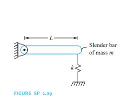
The static deflection of the spring in the system if Figure SP2.9 is \(m g / k\).Indicate whether the statement presented is true or false. If true, state why. If false, rewrite the statement to make it true. FIGURE SP 2.09 k Slender bar of mass m
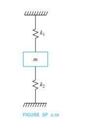
The springs in the system of Figure SP2.10 are in series.Indicate whether the statement presented is true or false. If true, state why. If false, rewrite the statement to make it true. m FIGURE SP 2.10
A shaft can be used as a spring of torsional stiffness \(J G / L\).Indicate whether the statement presented is true or false. If true, state why. If false, rewrite the statement to make it true.
Energy dissipation is used to calculate the equivalent viscous-damping coefficient for a combination of viscous dampers.Indicate whether the statement presented is true or false. If true, state why. If false, rewrite the statement to make it true.
The added mass of a fluid entrained by a vibrating system is determined by calculating the potential energy developed in the fluid.Indicate whether the statement presented is true or false. If true, state why. If false, rewrite the statement to make it true.
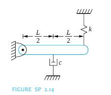
If it is desired to calculate the reactions at the support of Figure SP2.14, the effects of the static spring force and gravity cancel and do not need to be included on the FBD or in summing forces on the FBD.Indicate whether the statement presented is true or false. If true, state why. If false,
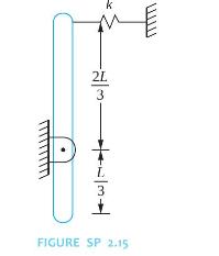
Gravity cancels with the static spring force, and hence, the potential energy of neither is included in potential energy calculations for the system of Figure SP2.15.Indicate whether the statement presented is true or false. If true, state why. If false, rewrite the statement to make it true.
What is the small angle assumption and how is it used?
When are the free-body diagrams of a system drawn when they are used to derive the differential equation of a linear SDOF system?
What is meant by "quadratic forms"?
The inertia effects of the spring in a mass-spring and viscous-damper system can be approximated by adding a particle of what to the mass?
What is the same in each spring for a combination of springs in parallel?
In general, how is the equivalent stiffness of a combination of springs calculated?
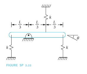
Draw a FBD showing the spring forces applied to the system of Figure SP2.22 at an arbitrary instant. Label the forces in terms of \(\dot{\theta}\). FIGURE SP 2.22 3
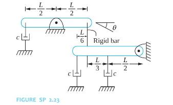
Draw a FBD showing the forces developed in the viscous dampers acting on the bar of Figure SP2.23 at an arbitrary instant. Label the forces in terms of \(\dot{\theta}\). FIGURE SP 2.23 L 6 Rigid bar L3 2
Describe the equivalent systems method.
When are static spring forces not drawn on the FBD of external forces?
Can the equivalent systems method be used to derive the differential equation of a nonlinear SDOF system? Explain.
What is the equivalent stiffness of springs of individual stiffnesses \(k_{1}\) and \(k_{2}\) placed in series?
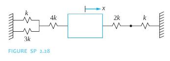
What is the equivalent stiffness of the springs in the system of Figure SP2.28? 3k FIGURE SP 2.28 4k 2k k
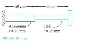
What is the equivalent torsional stiffness of the shafts in Figure SP2.29? -50 cm 60 cm Aluminum r = 20 mm FIGURE SP 2.29 Steel r = 15 mm
When a tensile force of \(300 \mathrm{~N}\) is applied to an elastic element, it has an elongation of \(1 \mathrm{~mm}\). What is the stiffness of the element?
What is the potential energy developed in the elastic element of Short Problem 2.30 when a \(300 \mathrm{~N}\) tensile force is applied?Data From Short Problem 2.30:When a tensile force of 300 N is applied to an elastic element, it has an elongation of 1 mm. What is the stiffness of the
What is the potential energy in the elastic element of Short Problem 2.30 when a \(300 \mathrm{~N}\) compressive force is applied?Data From Short Problem 2.30:When a tensile force of 300 N is applied to an elastic element, it has an elongation of 1 mm. What is the stiffness of the element?
A spring of torsional stiffness \(250 \mathrm{~N} \cdot \mathrm{m} / \mathrm{rad}\) has a rotation of \(2^{\circ}\) when a moment is applied. Calculate the potential energy developed in the spring.
What is the torsional stiffness of an annular steel shaft ( \(\left.\mathrm{G}=80 \times 10^{9} \mathrm{~N} / \mathrm{m}^{2}\right)\) with a length of \(2.5 \mathrm{~m}\), inner radius of \(10 \mathrm{~cm}\), and outer radius of \(15 \mathrm{~cm}\) ?
What is the torsional stiffness of a solid aluminum shaft ( \(\left.\mathrm{G}=40 \times 10^{9} \mathrm{~N} / \mathrm{m}^{2}\right)\) with a length of \(1.8 \mathrm{~m}\) and a radius of \(25 \mathrm{~cm}\) ?
What is the longitudinal stiffness of a steel bar \(\left(\mathrm{E}=200 \times 10^{9} \mathrm{~N} / \mathrm{m}^{2}\right)\) with a length of \(2.3 \mathrm{~m}\) and a rectangular cross section of \(5 \mathrm{~cm} \times 6 \mathrm{~cm}\) ?
What is the transverse stiffness of a cantilever steel beam \(\left(\mathrm{E}=200 \times 10^{9} \mathrm{~N} / \mathrm{m}^{2}\right)\) with a length of \(10 \mu \mathrm{m}\) and a rectangular cross section with a width of \(1 \mu \mathrm{m}\) and height of \(0.5 \mu \mathrm{m}\) ?
Calculate the static deflection in a linear spring of stiffness \(4000 \mathrm{~N} / \mathrm{m}\) when a mass of \(20 \mathrm{~kg}\) is hanging from it.
A spring of unstretched length of \(10 \mathrm{~cm}\) has a linear density of \(2.3 \mathrm{~g} / \mathrm{cm}\). The spring is attached between a fixed support and a block of mass of \(150 \mathrm{~g}\). What mass should be added to the block to approximate the inertia effects of the spring?
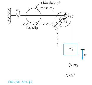
What is the kinetic energy of the system of Figure SP2.40 at an arbitrary instant in terms of \(x\), which is the downward displacement of the block of mass \(m_{1}\) ? Include an approximation of the inertia effects of the springs. The mass of each spring is \(\mathrm{ms}\). ms Thin disk of mass m
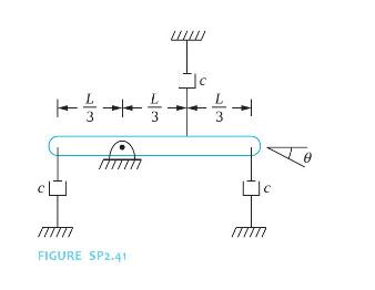
Calculate an equivalent torsional-damping coefficient for the system of Figure SP2.41 when \(\theta\), which is the clockwise angular rotation of the bar, is used as the generalized coordinate. FIGURE SP2.41 4 c c
Evaluate without using a calculator. The argument of the trigonometric function is in radians.(a) \(\sin 0.05\)(b) \(\cos 0.05\)(c) \(1-\cos 0.05\)(d) \(\tan 0.05\)(e) \(\cot 0.05\)(f) \(\sec 0.05\)(g) \(\csc 0.05\)
Evaluate without using a calculator.(a) \(\sin 3^{\circ}\)(b) \(\cos 3^{\circ}\)(c) \(1-\cos 3^{\circ}\)(d) \(\tan 3^{\circ}\)
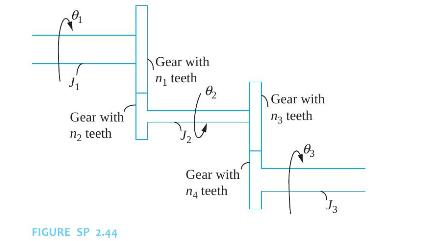
Calculate the equivalent moment of inertia of the three shafts of Figure SP2.44 when \(\theta_{2}\) is used as the generalized coordinate. Assume the gears mesh perfectly and their moments of inertia are negligible. 79 Gear with n teeth Gear with n teeth FIGURE SP 2.44 Gear with n4 teeth. Gear with
Match the quantity with the appropriate units(a) spring stiffness, \(k\)(i) \(\quad \mathrm{N} \cdot \mathrm{m}\)(b) torsional stiffness, \(k_{t}\)(ii) \(\mathrm{rad}\)(c) damping coefficient, \(c\)(e) torsional damping coefficient, \(c_{t}\)(f) potential energy, \(V\)(iii) \(\mathrm{N} \cdot
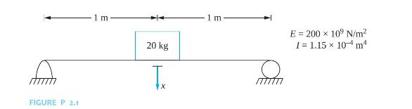
Determine the equivalent stiffness of a linear spring when a SDOF mass-spring model is used for the systems shown in Figures P2.1 with \(x\) being the chosen generalized coordinate. FIGURE P 2.1 m 20 kg TX 1 m mm E 200 x 109 N/m 1 = 1.15 10 m
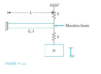
Determine the equivalent stiffness of a linear spring when a SDOF mass-spring model is used for the systems shown in Figures P2.2 with \(x\) being the chosen generalized coordinate. L k Massless beam E, I FIGURE P. 2.2 w m k T 1x
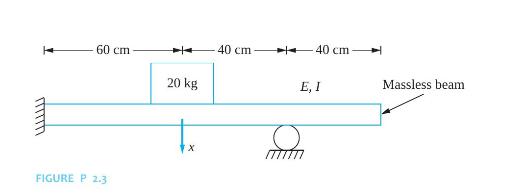
Determine the equivalent stiffness of a linear spring when a SDOF mass-spring model is used for the systems shown in Figures P2.3 with \(x\) being the chosen generalized coordinate. 60 cm 20 kg FIGURE P 2.3 40 cm 40 cm E, I x mm T Massless beam
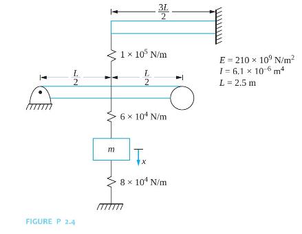
Determine the equivalent stiffness of a linear spring when a SDOF mass-spring model is used for the systems shown in Figures P2.4 with \(x\) being the chosen generalized coordinate. L 2 FIGURE P 2.4 3L 2 1 105 N/m L 2 E 210 x 109 N/m 1=6.1 10 6 m L = 2.5 m 6 104 N/m m I X 8 104 N/m
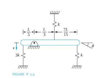
Determine the equivalent stiffness of a linear spring when a SDOF mass-spring model is used for the systems shown in Figures P2.5 with \(x\) being the chosen generalized coordinate. 7L 15 29 X 3k + m 3
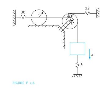
Determine the equivalent stiffness of a linear spring when a SDOF mass-spring model is used for the systems shown in Figures P2.6 with \(x\) being the chosen generalized coordinate. 3k FIGURE P 2.6 3rd 2k X
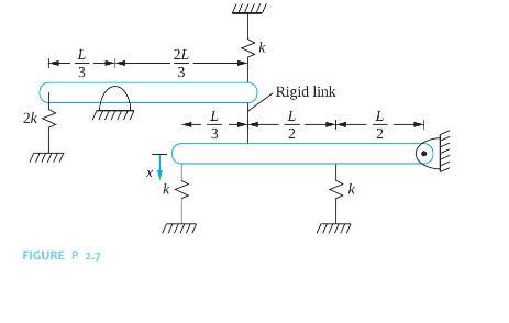
Determine the equivalent stiffness of a linear spring when a SDOF mass-spring model is used for the systems shown in Figures P2.7 with \(x\) being the chosen generalized coordinate. 2k 2L -- 3 k Rigid link 2 -- FIGURE P 2.7 x
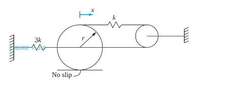
Determine the equivalent stiffness of a linear spring when a SDOF mass-spring model is used for the systems shown in Figures P2.8 with \(x\) being the chosen generalized coordinate.Figure P2.8: 3k No slip. X k
Two helical coil springs are made from a steel \(\left(\mathrm{E}=200 \times 10^{9} \mathrm{~N} / \mathrm{m}^{2}\right)\) bar with a radius of \(20 \mathrm{~mm}\). One spring has a coil diameter of \(7 \mathrm{~cm}\); the other has a coil diameter of \(10 \mathrm{~cm}\). The springs have 20 turns
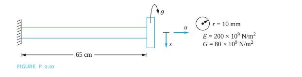
A thin disk attached to the end of an elastic beam has three uncoupled modes of vibration. The longitudinal motion, the transverse motion, and the torsional oscillations are all kinematically independent. Calculate the following for the system of Figure P2.10.(a) The longitudinal stiffness(b) The
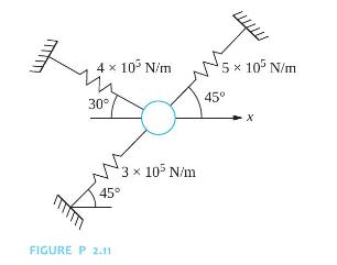
Find the equivalent stiffness of the springs in Figure P2.11 in the \(\mathrm{x}\) direction. 4 10 N/m 5 x 10 N/m 45 30 45 3 105 N/m FIGURE P 2.11 X
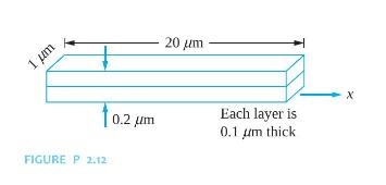
A bimetallic strip used as a MEMS sensor is shown in Figure P2.12. The strip, has a length of \(20 \mu \mathrm{m}\). The width of the strip is \(1 \mu \mathrm{m}\). It has an upper layer made of steel (E \(52103109 \mathrm{~N} / \mathrm{m} 2\) ) and a lower layer made of aluminum (E 5 \(803109
A gas spring consists of a piston of area \(A\) moving in a cylinder of gas. As the piston moves, the gas expands and contracts, changing the pressure exerted on the piston. The process occurs adiabatically (without heat transfer), so\[ p=C ho^{\gamma} \]where \(p\) is the gas pressure, \(ho\) is
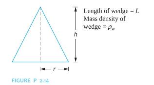
A wedge is floating stably on an interface between a liquid of mass density \(ho\), as shown in Figure P2.14. Let \(x\) be the displacement of the wedge's mass center when it is disturbed from equilibrium.(a) What is the buoyant force acting on the wedge?(b) What is the work done by the buoyant
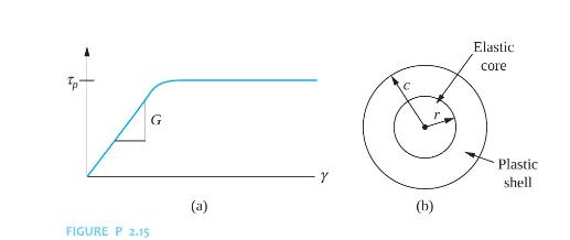
Consider a solid circular shaft of length \(L\) and radius \(c\) made of an elastoplastic material whose shear stress-shear strain diagram is shown in Figure P2.15(a). If the applied torque is such that the shear stress at the outer radius of the shaft is less than \(\tau_{p}\), a linear
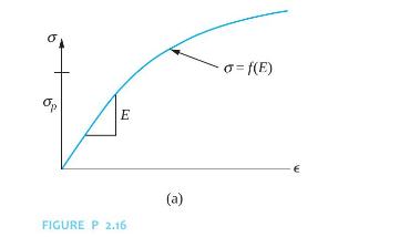
A bar of length \(L\) and cross-sectional area \(A\) is made of a material whose stressstrain diagram is shown in Figure P2.16. If the internal force developed in the bar is such that \(\sigma\sigma_{p}\). Let \(P=\sigma_{p} A+\delta P\) be the applied load which results in a deflection of
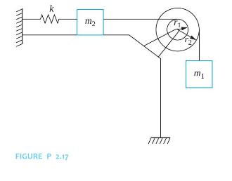
Calculate the static deflection of the spring in the system of Figure P2.17. k m2 FIGURE P 2.17 mi
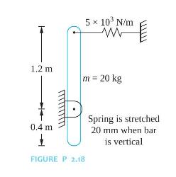
Determine the static deflection of the spring in the system of Figure P2.18. 1.2 m 5 10 N/m WE m = 20 kg 0.4 m 1 FIGURE P 2.18 Spring is stretched 20 mm when bar is vertical
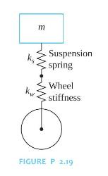
A simplified SDOF model of a vehicle suspension system is shown in Figure P2.19. The mass of the vehicle is \(500 \mathrm{~kg}\). The suspension spring has a stiffness of \(100,000 \mathrm{~N} / \mathrm{m}\). The wheel is modeled as a spring placed in series with the suspension spring. When the
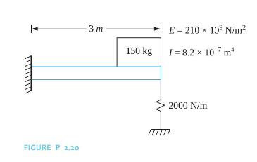
The spring of the system in Figure P2.20 is unstretched in the position shown. What is the deflection of the spring when the system is in equilibrium? FIGURE P 2,20 3 m 150 kg E 210 x 109 N/m I= 8.2 10-7 m 2000 N/m
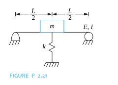
Determine the static deflection of the spring in the system of Figure P2.21. E m k FIGURE P 2.21 E, I
Showing 2000 - 2100
of 4547
First
14
15
16
17
18
19
20
21
22
23
24
25
26
27
28
Last
Step by Step Answers