New Semester
Started
Get
50% OFF
Study Help!
--h --m --s
Claim Now
Question Answers
Textbooks
Find textbooks, questions and answers
Oops, something went wrong!
Change your search query and then try again
S
Books
FREE
Study Help
Expert Questions
Accounting
General Management
Mathematics
Finance
Organizational Behaviour
Law
Physics
Operating System
Management Leadership
Sociology
Programming
Marketing
Database
Computer Network
Economics
Textbooks Solutions
Accounting
Managerial Accounting
Management Leadership
Cost Accounting
Statistics
Business Law
Corporate Finance
Finance
Economics
Auditing
Tutors
Online Tutors
Find a Tutor
Hire a Tutor
Become a Tutor
AI Tutor
AI Study Planner
NEW
Sell Books
Search
Search
Sign In
Register
study help
Computer science
systems analysis and design
control system analysis and design
Control System Analysis And Design 2nd Edition A.K. Tripathi - Solutions
Use frequency response approach to design a cascade lag-compensator for the system in unity feedback with loop transmittance\[\mathrm{G}(s)=\frac{\mathrm{K}}{s(0.25 s+1)}\]so as to achieve the following design specifications:(i) The steady state error to a ramp input \(\leq 0.01\)(ii) Phase margin
A system in unity feedback configuration has the loop transmittance\[\mathrm{G}(s)=\frac{\mathrm{K}}{s(2 s+1)}\]Using frequency response techniques, do the following:(a) Find \(\mathrm{K}\) to meet the specification on steady state error to a unit ramp input \(\leq 0.5\).(b) Sketch Bode plots using
Use frequency response methods to design a cascade, single, passive lag-lead compensator for a unity feedback system with open loop transmittance\[\mathrm{G}(s)=\frac{\mathrm{K}}{s(s+1)(s+2)}\]to meet the following design goals:(i) the ramp error coefficient \(\mathrm{K}_{v}=10
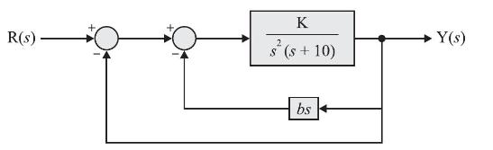
An architecture of a feedback compensator is shown in Fig. D 8.10. Design the parameters \(\mathrm{K}\) and \(b\) to achieve the following specifications:(i) Peak overshoot \(\leq 10 \%\)(ii) Settling time \(\leq 4\) seconds.Use root locus techniques. R(s) K 2 s (s + 10) bs Y(s)
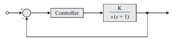
In the control system shown in the Fig. M8.1, the controller which can give zero steady state error to a ramp input, with \(\mathrm{K}=9\) isFig. M 8.1(a) proportional type(b) integral type(c) derivative type(d) proportional plus derivative type. Controller K s(s+1)
The gain crossover frequency and bandwidth of a control system are \(\omega_{c u}\) and \(\omega_{b u}\) respectively. A phase lag network is employed for compensating the system. If the gain crossover frequency and bandwidth of the compensated system are \(\omega_{c c}\) and \(\omega_{b c}\)
Consider the following statements regarding time domain analysis of control systems.1. Derivative control improves system's transient performance.2. Integral control does not improve system's steady state performance.3. Integral control can convert a second order system into a third order system.Of
Consider the following statements.In a feedback control system, lead compensator1. increases the margin of stability.2. speeds up transient response.3. does not affect the system error constant.Of these statements:(a) 2 and 3 are correct(b) 1 and 2 are correct(c) 1 and 3 are correct(d) 1, 2 and 3
A phase lag compensation will:(a) improve relative stability(b) increase the speed of response(c) increase bandwidth(d) increase overshoot.
The maximum phase shift that can be obtained by using a lead compensator with transfer function \(\mathrm{G}(s)=\frac{4(1+0.15 s)}{(1+0.05 s)}\) is equal to(a) \(15^{\circ}\)(b) \(30^{\circ}\)(c) \(45^{\circ}\)(d) \(60^{\circ}\).
Consider the following statements regarding a first order system with a proportional \((\mathrm{P})\) controller which exhibits an offset to a step input.In order to reduce the offset, it is necessary to1. increase the gain of the \(\mathrm{P}\).2. add derivative mode and increase gain of
An effect of phase lag-compensation on servo system performance is that(a) for a given relative stability, the velocity constant increases(b) for a given relative stability, the velocity constant decreases(c) the bandwidth of the system is increased(d) the time response is made faster.
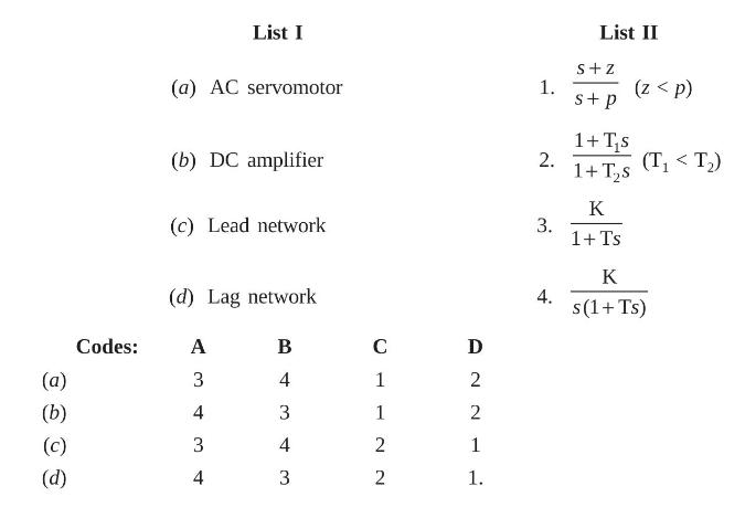
Match List I (System) with List II (Transfer function) and select the correct answer using the codes given below the Lists. (a) (b) (c) (d) Codes: List I (a) AC servomotor (b) DC amplifier (c) Lead network (d) Lag network A 3 4 3 4 B 34 4 3 4 3 C 1 1 2 NN 2 2 2 1 1. 1. 2. 3. 4. List II S+Z s+ p (z
A phase lead compensator has the transfer function\[\mathrm{G}_{c}(s)=\frac{10(1+0.04 s)}{(1+0.01 s)}\]The maximum phase angle lead provided by this compensator will occur at a frequency \(\omega_{m}\) equal to(a) \(50 \mathrm{rad} / \mathrm{sec}\)(b) \(25 \mathrm{rad} / \mathrm{sec}\)(c) \(10
The transfer function of a phase lead compensator is given by \(\frac{1+a \mathrm{Ts}}{1+\mathrm{Ts}}\) where \(a>1\) and \(\mathrm{T}>0\). The maximum phase shift provided by such a compensator is(a) \(\tan ^{-1}\left(\frac{a+1}{a-1}ight)\)(b) \(\tan ^{-1}\left(\frac{a-1}{a+1}ight)\)(c) \(\sin
Consider the following statements regarding a phase-lead compensator.1. It increases the bandwidth of the system2. It helps in reducing the steady state error due to ramp input3. It reduces the overshoot due to step input.Which of the above statements is/are correct?(a) 1 and 2(b) 1 and 3(c) 2 and
Consider the following performance characteristics.1. Reduced velocity constant for a given relative stability.2. Reduced gain crossover frequency.3. Reduced bandwidth.4. Reduced resonance peak of the system.Which of these performance characteristics are achieved with the phase-lag compensation?(a)
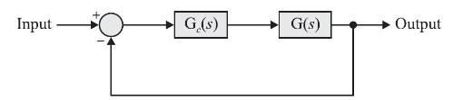
A closed loop system, employing lag-lead compensator \(\mathrm{G}_{c}(\mathrm{~s})\) is shown in the Fig. M8.14:If \(\mathrm{G}(\mathrm{s})\) has 3 poles in the left half of s-plane, then the slope of the Bode plot for \(\left|\mathrm{G}(\mathrm{s}) \mathrm{G}_{c}(s)ight|\) in the highest frequency
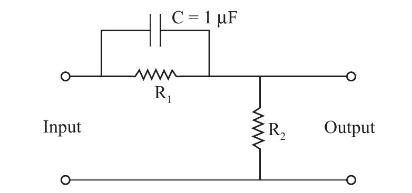
The transfer function of a phase lead network, as shown in the Fig. M8.14 is \(\frac{\mathrm{K}(1+0.3 s)}{(1+0.17 s)}\)The values of \(\mathrm{R}_{1}\) and \(\mathrm{R}_{2}\) are respectively:(a) \(300 \mathrm{k} \Omega\) and \(300 \mathrm{k} \Omega\)(b) \(300 \mathrm{k} \Omega\) and \(400
Which one of the following statements is correct?A plant is controlled by a proportional controller. If a time delay element is introduced in the loop, its(a) phase margin remains the same(b) phase margin increases(c) phase margin decreases(d) gain margin increases.
Which one of the following statements is correct?The effects of phase lead compensator on gain crossover frequency \(\left(\omega_{g c}ight)\) and the bandwidth (BW) are(a) that both are decreased(b) that \(\omega_{g c}\) is decreased but BW is increased(c) that \(\omega_{g c}\) is increased but BW
How does cascading an integral controller in the forward path of a control system affect the relative stability (RS) and the steady-state error (SSE) of that system?(a) Both are increased(b) RS is reduced but SSE is increased(c) RS is increased but SSE is reduced(d) Both are reduced.
Consider the following statements for phase-lead compensation:1. Phase-lead compensation shifts the gain crossover frequency to the right.2. The maximum phase-lead angle occurs at the arithmetic mean of the corner-frequencies of the phase-lead network.3. Phase-lead compensation is effective when
The phase lead compensation is used to(a) increase rise time and decrease overshoot(b) decrease both rise time and overshoot(c) increase both rise time and overshoot(d) decrease rise time and increase overshoot.
Maximum phase-lead of the compensator \(\mathrm{D}(s)=(0.5 s+1) /(0.05 s+1)\), is(a) 52 deg at \(4 \mathrm{rad} / \mathrm{sec}\).(b) \(52 \mathrm{deg}\) at \(10 \mathrm{rad} / \mathrm{sec}\).(c) 55 deg at \(12 \mathrm{rad} / \mathrm{sec}\).(d) None of the answers in \((a),(b)\) and \((c)\) is
A PD controller is used to compensate a system. Compared to the uncompensated system, the compensated system has(a) a higher type number(b) reduced damping(c) higher noise amplification(d) larger transient overshoot.
The system with \(\mathrm{G}(s)=\frac{900}{s(s+1)(s+9)}\) is to be compensated such that its gain cross over frequency becomes same as its uncompensated phase cross over frequency and provides phase margin of \(45^{\circ}\). To achieve this goal, one may use(a) a lag compensator that contributes
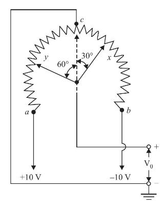
A single turn \(10 \mathrm{~K}\) potentiometer with rotation angle of \(320^{\circ}\), is shown in Fig. P9.1. The fixed terminals \(\boldsymbol{a}\) and \(\boldsymbol{b}\) are connected to \(+10 \mathrm{~V}\) and \(-10 \mathrm{~V}\) DC supply respectively. The centre tap \(c\) is grounded.
A multi turn wire wound rotary potentiometer has following specifications:Total number of turns, \(\mathrm{N}=5\)Total resistance, \(\mathrm{R}_{a}=10 \mathrm{k} \Omega\)Total number of winding turns \(=8000\)Fixed reference voltage, \(\mathrm{V}_{\mathrm{R}}=50 \mathrm{~V}\)(a) With the movable
A helical multi turn potentiometer has following specifications:Total resistance, \(\mathrm{R}_{a}=20 \mathrm{k} \Omega\)Total number of turns, \(\mathrm{N}=10\)Fixed reference voltage, \(\mathrm{V}_{\mathrm{R}}=80 \mathrm{~V}\)\[\% \text { linearity }=1 \%\](a) Find the range of voltage at
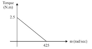
The torque-speed curve of a DC servo motor is shown in Fig P 9.5. Determine mechanical time constant of motor if moment of inertia of rotor is \(1.2 \times 10^{-4} \mathrm{~kg} \cdot \mathrm{m}^{2}\). Torque (N.m) 2.5 425 (0 (rad/sec)
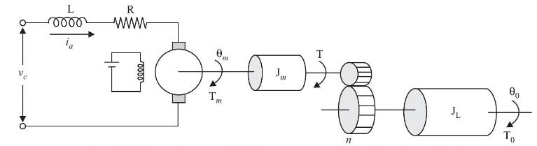
As shown in Fig. P9.6, an armature controlled DC servo motor drives a load with moment of inertia \(\mathrm{J}_{\mathrm{L}}\). The torque developed by motor is \(\mathrm{T}\). The moment of inertia of motor rotor is \(\mathrm{J}_{m}\). The angular displacement of motor rotor and load element are
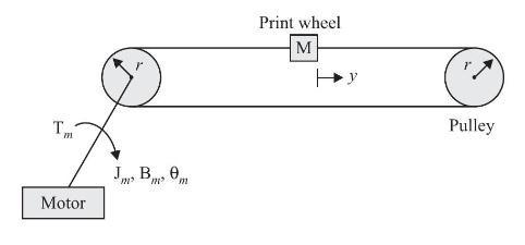
The print wheel control system of a word processor, is shown in Fig P9.7. The control system consists of a DC motor driving belts and pulleys. Assume that belts are rigid. \(\mathrm{T}_{m}(t)\) is motor torque, \(\theta_{m}(t)\) is motor displacement (angular), \(y(t)\) is linear displacement of
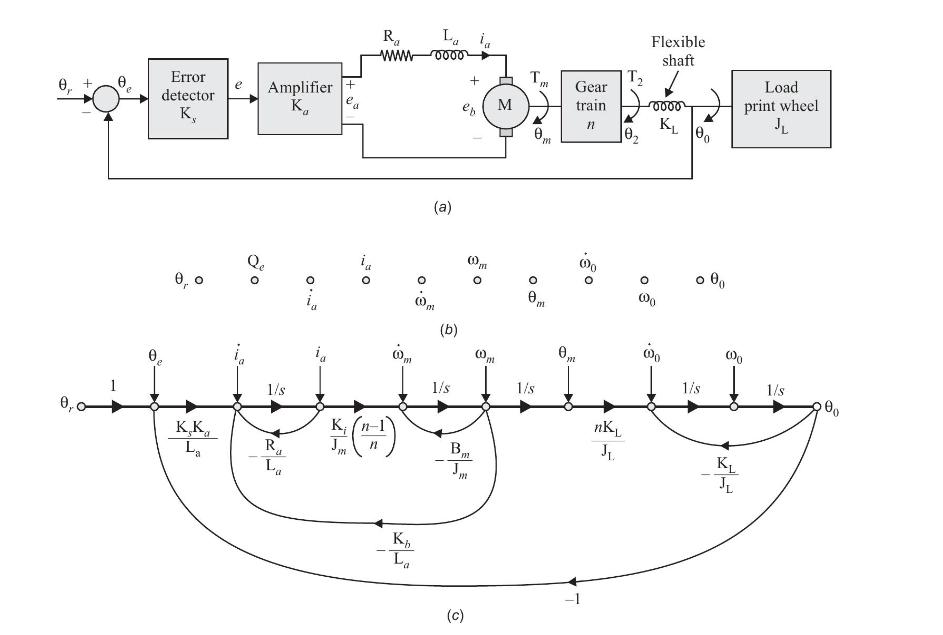
Figure P9.8(a) shows the schematic diagram of a DC motor control system for controlling the print wheel as load in an electronic word processor. The control system variables and parameters are defined as follows:\(\mathrm{K}_{s}\) = gain of error detector (V/rad)\(\mathrm{K}_{i}=\) torque
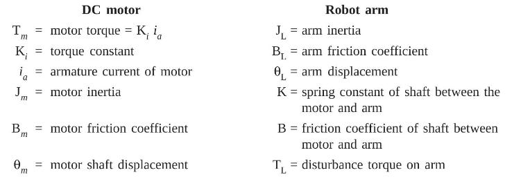
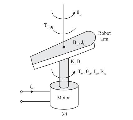
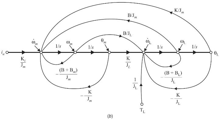
The linear model of a robot arm system being driven by a DC motor, is shown in Fig. P 9.9 (a). The system variables and parameters are given below:(a) Write equations describing dynamics of system with \(i_{a}(t)\) and \(\mathrm{T}_{\mathrm{L}}(t)\) as inputs and \(\theta_{m}(t)\) and
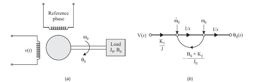
An AC servo motor is shown in Fig. P9.10(a). The voltage \(v(t)\) applied to control winding, is phase displaced by \(90^{\circ}\) with respect to constant amplitude voltage applied to reference phase. The motor is so designed that the developed torque is approximated
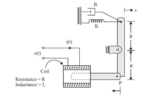
An electromechanical system is shown in Fig. P 9.11. On energising the solenoid with \(e(t)\), the lower arm of lever \(\mathrm{P}\) moves to the left and upper arm to the right. The coil has resistance \(\mathrm{R}\) and inductance L. The solenoid pull \(\mathrm{F}=\mathrm{K} i(t)\) where \(i(t)\)
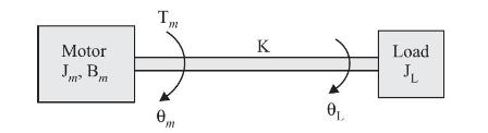
As shown in Fig. D9.1, a motor is coupled to an inertial load through a shaft. Significant variables and parameters involved in the system are as follows:\[\begin{aligned}\mathrm{T}_{m}(t) & =\text { motor torque } \\\mathrm{J}_{m} & =\text { motor inertia } \\\mathrm{B}_{m} & =\text {
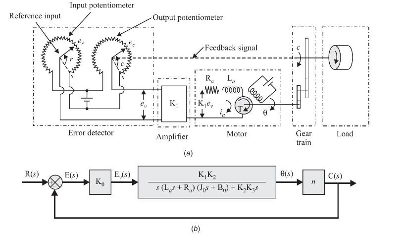
A position control system is shown in Fig. D9.2(a). The angular position \(\boldsymbol{r}\) is the reference input to the system. The output shaft position determines the angular position \(\boldsymbol{c}\) of wiper arm of the output potentiometer. The error voltage \(e_{v}=e_{r}-e_{c}\) where
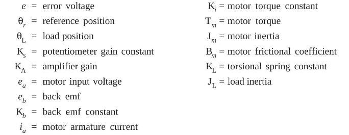
The position control system is shown in Fig. D9.3(a). The control parameters and variables are defined asWrite state equations of the system and draw state diagram (signal flow graph) using the nodes as shown in Fig. D9.3(b). e 0 = reference position r OL = load position K = potentiometer gain
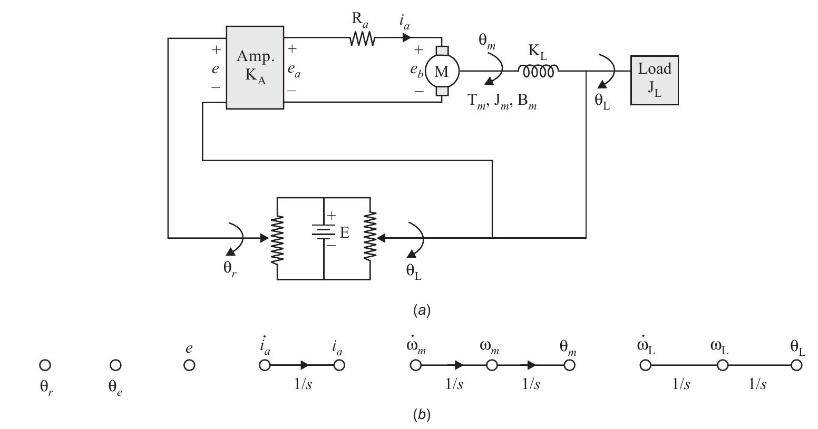
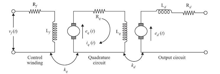
As shown in Fig. D 9.4, the amplidyne is considered as two stage cascaded generator. Obtain the transfer function model \(\mathrm{E}_{d}(s) / \mathrm{V}_{f}(s)\). The symbols used in the circuit have their usual meaning. WWW Rq THI L eq (1) ig (t) Quadrature circuit ka R WWW Control winding La Ra
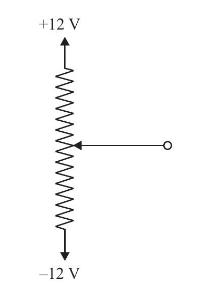
\(\mathrm{A} 50 \mathrm{~K} \Omega, 10\) turn potentiometer has \(\pm 12 \mathrm{~V}\) supply connected to fixed terminals as shown in Fig. D9.5.(a) Determine gain constant of potentiometer in V/rad.(b) Find open circuit (unloaded) output voltage when the shaft is rotated \(70^{\circ}\) from
A wire wound potentiometer is expected to contribute resolution of \(0.02 \%\). The required number of winding turns, is(a) 4000(b) 5000(c) 2000(d) 1500.
A tachometer has sensivity of \(4 \mathrm{~V} / 1000 \mathrm{rpm}\). The output voltage for shaft speed of 30 \(\mathrm{rad} / \mathrm{sec}\), will be approximately(a) \(12 \mathrm{~V}\)(b) \(2.24 \mathrm{~V}\)(c) \(1.14 \mathrm{~V}\)(d) \(3 \mathrm{~V}\).
For a tachometer, if \(\theta(t)\) is rotor displacement in radians, \(e(t)\) is the output voltage and \(k_{t}\) is the tachometer constant in V/rad. \(\mathrm{sec}^{-1}\), then the transfer function \(\mathrm{E}(\mathrm{s}) / \theta(s)\) will be(a) \(k_{t} s^{2}\)(b) \(k_{t} / s\)(c) \(k_{t}
The gear trains are used in servo system design in order to(a) increase the speed and the torque(b) reduce the speed and increase the torque(c) reduce the speed and the torque(d) increase the speed and reduce the torque.
In design of two phase AC servo motor, special care should be taken such that(a) the inertia is high(b) the friction is low(c) torque-speed curve has positive slope(d) torque-speed curve has negative slope.
The conventional two phase induction motor cannot be used in design of servo system because(a) its cost is high(b) it is less accurate(c) it is noisy(d) it destabilises the servo system.
The purpose of the series quadrature windings in an amplidyne is to(a) neutralize the effect of armature reaction(b) reduce commutation difficulties(c) increase gain(d) increase the response time.
In position control system, the device used for providing rate feedback voltage, is called(a) potentiometer(b) synchro transmitter(c) synchro transformer(d) tacho generator
A synchro transmitter-receiver unit is a(a) two phase AC device(b) three phase AC device(c) DC device(d) single phase ac device.
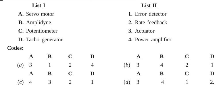
Match the control system components in List I with their function in List II and select the correct answer using the codes given below the lists: List I A. Servo motor B. Amplidyne C. Potentiometer D. Tacho generator Codes: A (a) 3 A (c) 4 B 1 B 3 C 2 C 2 D 4 D 1 List II 1. Error detector 2. Rate
For a two phase servo motor, which one of the following statements is not true?(a) The rotor diameter is small.(b) The rotor resistance is low.(c) The applied voltages are seldom balanced.(d) The torque-speed characteristics are linear.
In case of synchro error detector, the electrical zero position of control transformer is obtained when angular displacement between rotors, is(a) \(0^{\circ}\)(b) \(45^{\circ}\)(c) \(90^{\circ}\)(d) \(180^{\circ}\).
Consider the following for a variable reluctance stepper motor used in control system.1. The static torque acting on the rotor is a function of angular misalignment between stator and rotor teeth.2. There are two positions of zero torque: \(\theta=0^{\circ}\) and \(180^{\circ} / \mathrm{T}\) (
In a two phase \(A C\) servo motor, the rotor has resistance \(\mathrm{R}\) and reactance \(\mathrm{X}\). The torque speed characteristics of the servo motor will be linear provided that(a) \(\frac{\mathrm{X}}{\mathrm{R}}
Which of the following can work as error detecting devices?1. A pair of potentiometers2. A pair of synchros3. A differential transformer4. An amplidyne5. A control transformerSelect the correct answer using the following codes:(a) 1, 2 and 5(b) 2, 3, 4 and 5(c) 1, 3, 4 and 5(d) 1, 2, 3 and 4.
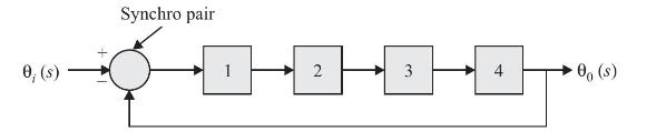
The block diagram shown below, represents a hybrid servo system.The blocks labelled 1, 2, 3 and 4 are respectively(a) amplifier, demodulator, DC servo motor and load(b) demodulator, amplifier, DC servo motor and load(c) amplifier, DC servo motor, demodulator and load(d) demodulator, DC servo motor,
Which of the following components can be used as a rotating amplifier in a control system?1. An amplidyne2. A separately excited DC generator3. A self-excited DC generator4. A synchroSelect the correct answer using the codes given below:Codes:(a) 3 and 4(b) 1 and 2(c) 1, 2 and 3(d) 1, 2, 3 and 4 .
In the field controlled DC motor, the entire damping is contributed by(a) the armature resistance(b) the back emf(c) the motor friction and load(d) feed resistance.
For two phase AC servo motor, if \(R\) is resistance of rotor, \(X\) is reactance of rotor, \(L\) is length of rotor and \(\mathrm{D}\) is diameter of rotor then(a) \(\mathrm{X} / \mathrm{R}\) and \(\mathrm{L} / \mathrm{D}\) are both small.(b) \(\mathrm{X} / \mathrm{R}\) is large but \(\mathrm{L} /
Which of the following can be included in a control system such that total number of poles and zeros, does not change?(a) Amplidyne(b) DC servo motor(c) tachometer(d) AC servo motor.
In a two phase \(A C\) servo motor with small \(X / R\) ratio, maximum torque occurs at(a) synchronous speed(b) low speed(c) high speed(d) rated speed.
A stepper motor has stator wound for two phase and rotor consisting of 24 teeth. The step movement \(\theta\) is(a) \(7.5^{\circ}\)(b) \(15^{\circ}\)(c) \(3.75^{\circ}\)(d) \(11.25^{\circ}\)
A stepper motor has step angle of \(1.8^{\circ}\) and the pulse frequency is 300 pulses per second. Now consider the following statements.1. The resolution of motor is 200 steps/revolution.2. The speed of motor is \(90 \mathrm{rpm}\).3. The number of steps, the motor moves in 15 revolutions is 3000
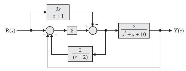
Reduce the block diagram shown in Fig. P3.1 to obtain system transfer function. R(s) 3.s s+1 + 8 2 (-2) S s+s+10 Y(3)
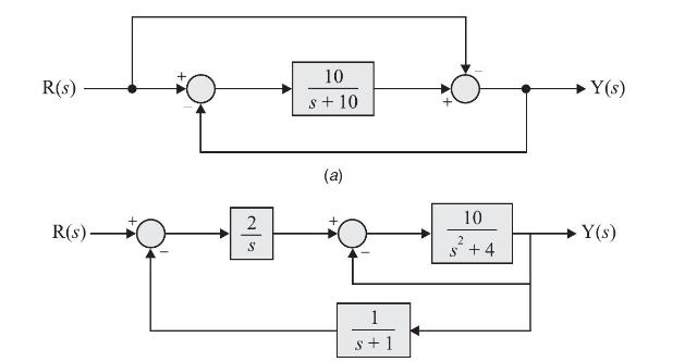
Use the rules of block diagram algebra to find the transfer function of the systems shown in Fig. D3.1(a), (b) and (c). R(s) R(s) 2 S 10 s + 10 (a) 1 s+1 10 2 s +4 Y(s) Y(s)
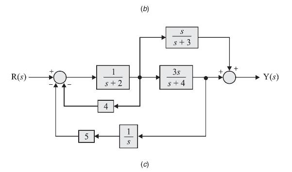
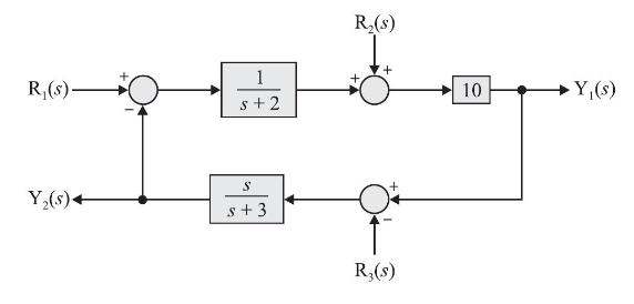
Reduce the block diagram shown in Fig. D3.2 to obtain six transfer functions. R(s)- Y(s)+ 1 s+2 S s+3 R(s) + R(s) 10 Y(s)
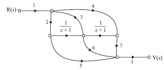
Use Mason's gain rule to find transfer function of system shown in Fig. P3.10. R (s) 1 + 3 2 s +1 s + 1 6 5 7 Y (s)
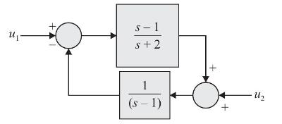
The system shown in figure below is(a) stable(b) unstable(c) conditionally stable(d) stable for input \(u_{1}\) but unstable for input \(u_{2}\). U s-1 s+2 1 (s-1) Uz
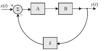
Fig. P1.1 shows the block diagram of a control system. The system in block A has an impulse response \(h_{\mathrm{A}}(t)=e^{-t} u(t)\). The system in block B has an impulse response \(h_{\mathrm{B}}(t)=e^{-2 t} u(t)\). The block ' \(k\) ' amplifies its input by a factor \(k\). For the overall
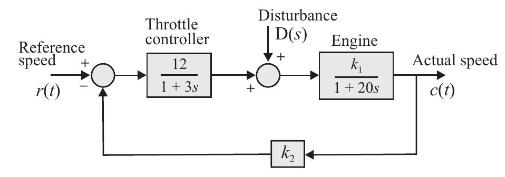
A speed control system of an engine is shown in Fig. P1.2. Determine:(a) Sensitivity of closed loop system to changes in engine gain \(k_{1}\) and tachometer feedback gain \(k_{2}\).(b) Steady state speed for reference speed \(=50 \mathrm{~km} / \mathrm{hr}, k_{1}=100, k_{2}=1\) and \(d(t)=0\)(c)
The forward path transfer function of a position control system with velocity feedback is given by\[\mathrm{G}(s)=\frac{\mathrm{K}}{s(s+p)}\]Determine the sensitivity of the transfer function of the closed loop system to changes in \(\mathrm{K}, p\) and \(\alpha\) for transfer function of the
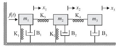
Write differential equations governing the behaviour of mechanical system shown in Fig. P1.4 and obtain analogous electrical networks based on;(a) \(f-v\) analogy(b) f-i analogy. f(t) K 00000 K3 m 00000 m -|B K 00000 HX K 00000 B m3 B3
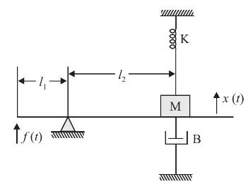
Find transmittance \(\frac{\mathrm{X}(s)}{\mathrm{F}(s)}\) for the system shown in Fig. P1.5 tro 0000 K M B x (t)
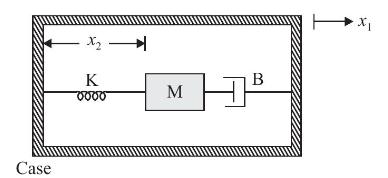
Fig. P 1.6 shows an accelerometer. It is so designed that the position x2x2 of mass with respect to the case is approximately proportional to the case acceleration d2x1dt2d2x1dt2. Find the transmittance that relates x2x2 to the case acceleration, r(t)=d2x1dt2r(t)=d2x1dt2 in terms of K,MK,M and BB.
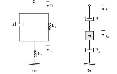
Obtain transfer function of each of two mechanical systems given in Fig. P 1.7, where \(x_{i}\) represents input displacement and \(x_{0}\) represents output displacement. B eeee (a) K 0000 T K Xo - B m (b) B Txi Xo
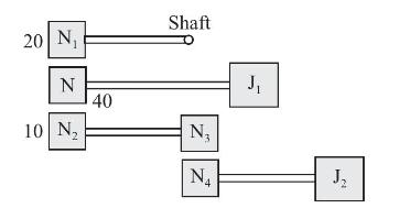
Find equivalent inertia referred to shaft shown in Fig. P1.8.sf asdf asdGiven \(\frac{\mathrm{N}_{3}}{\mathrm{~N}_{4}}=\frac{5}{4}\) 20 N N 10 N 40 Shaft N N 4 J J
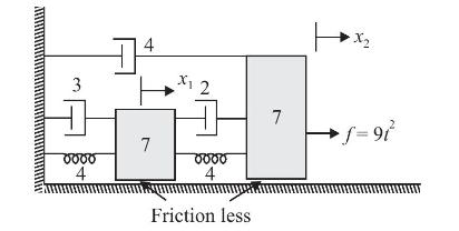
Write simultaneous Laplace transformed differential equations for mechanical system shown in Fig. D1.1. Assume zero initial conditions. 3 0000 4 1 4 7 X 2 oooo 4 Friction less 7 X f=91
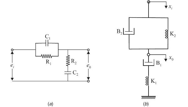
Show that the systems in Fig. D1.2 (a). and D1.2 (b) are analogous. C www R (a) www R :C B 00:00 (b) B K 0000 K xo
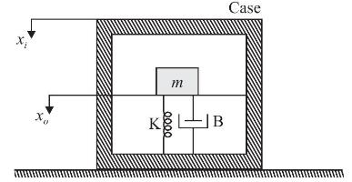
Fig. D1.3 shows a schematic diagram of a seismograph. \(x_{i}\) and \(x_{o}\) represent displacements of case and mass \(m\) respectively with respect to inertial space. If \(y\) is displacement of mass \(m\) with respect to case, find transmittance \(\mathrm{Y}(s) / \mathrm{X}_{i}(s)\). K m 0000 B
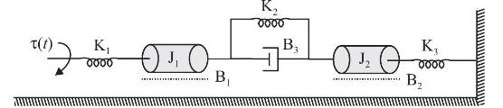
For the rotational system shown in Fig. D1.4, find Laplace transformed system equations and draw electrical analogs using(a) Force-voltage analogy(b) Force-current analogy. to K 0000 OTO B K 0000 B 3 020 K oooo B
Consider the control strategy structures shown in Fig. D1.5 (a) and (b). Given nominal value of \(K=1\), show that both have same transfer function \(C(s) / X(s)\). Evaluate \(\left|S_{K}^{T} \right|\) for both at \(\omega=5 \mathrm{rad} / \mathrm{sec}\) and comment on result. Does information
The following differential equations represent LTI systems with input \(x(t)\) and output \(y(t)\). Find transfer functions.(a) \(\dddot{y}(t)+2 \ddot{y}(t)+5 \dot{y}(t)+6 y(t)=3 \dot{x}(t)+x(t)\)(b) \(\dddot{y}(t)+10 \ddot{y}(t)+2 \dot{y}(t)+y(t)+2 \int_{0}^{t} y(\tau) d \tau=\dot{x}(t)+2 x(t)\)
The dynamics of a multi input and multi output system with inputs \(x_{1}(t)\) and \(x_{2}(t)\) and outputs \(y_{1}(t)\) and \(y_{2}(t)\) is described by following set of differential equations.\[\begin{aligned}\ddot{y}_{1}(t)+2 \dot{y}_{1}(t)+3 y_{2}(t) & =x_{1}(t)+x_{2}(t) \\\ddot{y}_{2}(t)+3
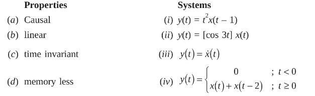
Determine which of the following properties hold and which do not hold for each of systems with input \(x(t)\) and output \(y(t)\) given below. Properties (a) Causal (b) linear (c) time invariant (d) memory less Systems (i) y(t) = tx(t-1) (ii) y(t) = [cos 3t] x(t) (iii) y(t) = x(t) (iv) y(t) = 0 ;
As compared to a closed-loop system, an open-loop system is:(a) more stable as well as more accurate(b) less stable as well as less accurate(c) more stable but less accurate(d) less stable but more accurate.
Consider the following statements regarding the advantages of closed-loop negative feedback control system over open-loop system:1. The overall reliability of the closed-loop system is more than that of open-loop system2. The transient response in the closed-loop system decays more quickly than in
Consider the following statements regarding a linear system \(y=f(x)\) :1. \(f\left(x_{1}+x_{2}\right)=f\left(x_{1}\right)+f\left(x_{2}\right)\)2. \(f[x(t+T)]=f[x(t)]+f[x(T)]\)3. \(f(K x)=K f(x)\)Of these statements:(a) 1,2 and 3 are correct(b) 1 and 2 are correct(c) 2 alone is correct(d) 1 and 3
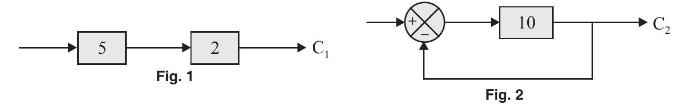
Consider the systems shown in Fig. 1 and Fig. 2. If the forward path gain is reduced by \(10 \%\) in each system, then the variation in \(C_{1}\) and \(C_{2}\) will be respectively:(a) \(10 \%\) and \(10 \%\)(b) 2% and 10%(c) \(5 \%\) and \(1 \%\)(d) \(10 \%\) and \(1 \%\) 5 Fig. 1 2 C 10 Fig. 2 C
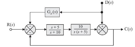
In the system shown below, to eliminate the effect of disturbance \(\mathrm{D}(s)\) on \(\mathrm{C}(s)\), the transfer function \(\mathrm{G}_{d}(\mathrm{~s})\) should be:(a) \(\frac{(s+10)}{10}\)(b) \(\frac{s(s+10)}{10}\)(c) \(\frac{10}{(s+10)}\)(d) \(\frac{10}{s(s+10)}\) R(S) G. (s) s+ 5 s+10 10 s
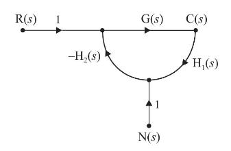
A closed-loop system is shown below. The noise transfer function \(\frac{C_{n}(s)}{N(s)}\left[C_{n}(s)= \right.\) output corresponding to noise input \(\mathrm{N}(\mathrm{s})\) ] is approximately:(a) \(\frac{1}{\mathrm{G}(s) \mathrm{H}_{1}(s)}\) for \(\left|\mathrm{G}(s) \mathrm{H}_{1}(s)
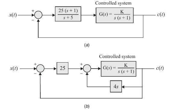
A linear system, initially at rest, is subjected to an input signal;..............\[r(t)=1-e^{-t}(t \geq 0)\]The response of the system for \(t \geq 0\) is given by\[c(t)=1-e^{-2 t}\]The transfer function of the system is:(a) \(\frac{(s+2)}{(s+1)}\)(b) \(\frac{(s+1)}{(s+2)}\)(c)
The impulse response of a system is \(5 e^{-10 t}\). Its step response is equal to(a) \(0.55 e^{-10 t}\)(b) \(5\left(1-e^{-10 t}\right)\)(c) \(0.5\left(11-e^{-10 t}\right)\)(d) \(10\left(1-e^{-10 t}\right)\)
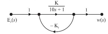
Given: \(\mathrm{KK}_{t}=99\); \(s=j 1 \mathrm{rad} / \mathrm{s}\) : the sensitivity of the closed-loop system shown below, to variation in parameter \(\mathrm{K}\) is approximately:(a) 0.01(b) 0.1(c) 1.0(d) 10 E,(s) 1 K 10s +1 - K w(s)
Which one of the following systems is open-loop?(a) The respiratory system of man(b) A system for controlling the movement of the slide of a copying milling machine(c) A thermostatic control(d) Traffic light control.
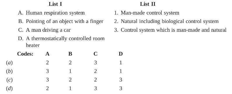
Match List-I (Physical action or activity) with List-II (Category of system) and select the correct answer using the codes given below the Lists: (a) (b) (c) (d) List I A. Human respiration system B. Pointing of an object with a finger C. A man driving a car D. A thermostatically controlled room
Feedback control systems are(a) insensitive to both forward and feedback path parameter changes(b) less sensitive to feedback path parameter changes than to forward path parameter changes(c) less sensitive to forward path parameter changes than to feedback path parameter changes(d) equally
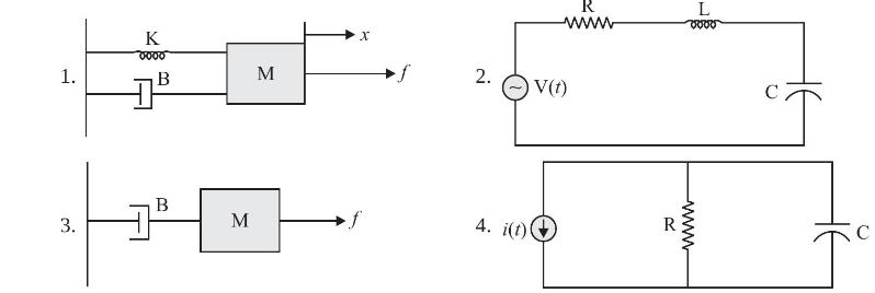
Consider the following systems:Which of these systems can be modelled by the differential equation of form\[a_{2} \frac{d^{2} y(t)}{d t^{2}}+a_{1} \frac{d y(t)}{d t}+a_{0} y(t)=x(t)\](a) 1 and 2(b) 1 and 3(c) 2 and 4(d) 1, 2 and 4 1. 3. K 0000 B B M M X 2. 4. i(t) R www V(t) R L 8000 www J
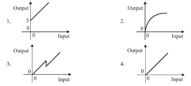
Which one of the following input-output relationship is that of a linear system 1. 3. Output 5 0 Output 0 0 Input Input 2. 4. Output Output 0 0 Input Input
Showing 300 - 400
of 480
1
2
3
4
5
Step by Step Answers