New Semester
Started
Get
50% OFF
Study Help!
--h --m --s
Claim Now
Question Answers
Textbooks
Find textbooks, questions and answers
Oops, something went wrong!
Change your search query and then try again
S
Books
FREE
Study Help
Expert Questions
Accounting
General Management
Mathematics
Finance
Organizational Behaviour
Law
Physics
Operating System
Management Leadership
Sociology
Programming
Marketing
Database
Computer Network
Economics
Textbooks Solutions
Accounting
Managerial Accounting
Management Leadership
Cost Accounting
Statistics
Business Law
Corporate Finance
Finance
Economics
Auditing
Tutors
Online Tutors
Find a Tutor
Hire a Tutor
Become a Tutor
AI Tutor
AI Study Planner
NEW
Sell Books
Search
Search
Sign In
Register
study help
physics
particle physics
Principles And Practice Of Physics 2nd Global Edition Eric Mazur - Solutions
The objective lens in a telescope that produces a 50-fold angular magnification has a focal length of \(3.0 \mathrm{~m}\). What is the focal length of the eyepiece lens?
An object is placed \(500 \mathrm{~mm}\) away from a diverging thin lens for which the focal length is \(-200 \mathrm{~mm}\). What are (a) the image distance(b) the magnification of the image?
Two lenses with focal lengths \(f_{1}=200 \mathrm{~mm}\) and \(f_{2}=\) \(300 \mathrm{~mm}\) are placed facing each other a distance \(d=1.5 \mathrm{~m}\) apart, with lens 1 to the left of lens 2 . What is the location of the image formed of an object placed \(250 \mathrm{~mm}\) to the left of lens
Sunlight reflected off a mirror you are holding is focused at a point \(100 \mathrm{~mm}\) in front of the mirror. What is the radius of curvature of the mirror?
A spherical mirror with radius of curvature \(R=200 \mathrm{~mm}\) is used to form an image of an object placed a distance \(d=150 \mathrm{~mm}\) in front of the mirror. Where does the image appear? \(\cdot\)
A converging mirror has a focal length of \(200 \mathrm{~mm}\). Calculate the image distance and magnification for an object located (a) halfway between the focal point and the mirror, (b) at the focal point, (c) halfway between the focal point and the center of curvature, (d) at the center of
A plano-convex lens has a focal length of \(150 \mathrm{~mm}\), and the material out of which the lens is made has an index of refraction of 1.5 . What is the radius of curvature of the convex surface?
An object that is \(50 \mathrm{~mm}\) tall is placed \(75 \mathrm{~mm}\) in front of a converging thin lens. If the image is inverted and \(100 \mathrm{~mm}\) tall, what are (a) the distance of the image from the lens (b) the focal length of the lens?
When an object is placed \(1.5 \mathrm{~m}\) in front of a converging mirror, an image of the object appears twice as high behind the mirror.(a) Is the image real or virtual? (b) Is it upright or inverted?(c) What is the mirror's radius of curvature?
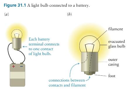
Consider the system comprising the singleloop circuit shown in Figure 31.1a, including the light and thermal energy generated by the bulb.(a) Is this system closed?(b) Is the energy of the system constant?(c) Where do the light energy and the thermal energy come from? Figure 31.1 A light bulb
Two wires connect the plates of a charged capacitor to the contacts of a light bulb. (a) Does this assembly constitute a circuit? If so, identify the power source and the load. (b) Does the bulb glow? (c) What energy conversions take place after the bulb and capacitor are connected?
Suppose you connect a light bulb to a battery. How do you expect the current in the bulb to vary over the course of \((a)\) a minute, \((b)\) a few days?
Does an electron lose or gain electric potential energy (a) while moving inside a battery from the positive terminal to the negative terminal (b) while moving through the rest of the circuit from the negative battery terminal to the positive terminal?(c) While flowing through the wire and load
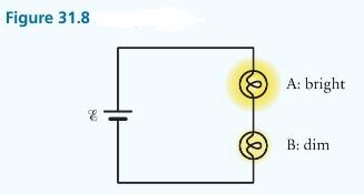
(a) Which light bulb in Example 31.2 has the greater resistance?(b) Suppose you connect each bulb separately to the battery. Do you expect the current in bulb A to be greater than, equal to, or smaller than that in bulb B?Data from Example 31.2In Figure 31.8, two light bulbs are connected to each
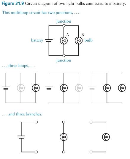
In Figure 31.9, treat the parallel combination of two light bulbs as a single circuit element. Is the resistance of this element greater than, equal to, or smaller than the resistance of either bulb? Figure 31.9 Circuit diagram of two light bulbs connected to a battery. This multiloop circuit has
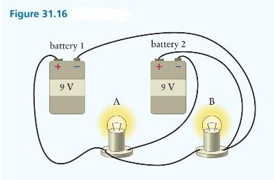
If each battery in Figure 31.16 has an emf of \(9 \mathrm{~V}\), what is the magnitude of the potential difference across \((a)\) bulb \(\mathrm{A}\) and \((b)\) bulb \(\mathrm{B}\) ? (c) If the two bulbs are identical, which one glows more brightly? Figure 31.16 battery 1 battery 2 9 V A 9 V B
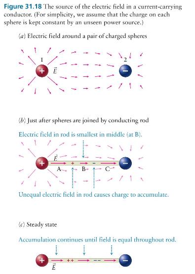
Suppose the distance between the spheres in Figure 31.18 is \(\ell\) and the potential difference between them is \(V_{12}\). What is the magnitude of the electric field inside the connecting rod? Figure 31.18 The source of the electric field in a current-carrying conductor. (For simplicity, we
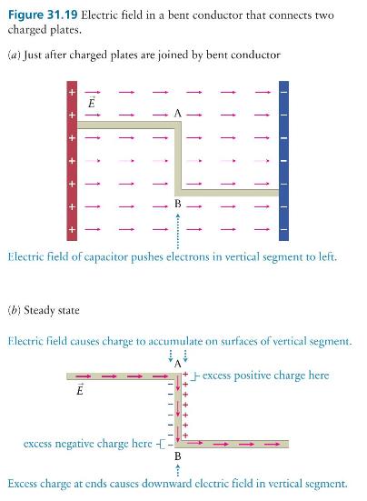
Sketch the electric field lines inside the conductors in Figures 31.18 and 31.19. Figure 31.18 The source of the electric field in a current-carrying conductor. (For simplicity, we assume that the charge on each sphere is kept constant by an unseen power source.) (a) Electric field around a pair of
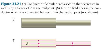
If a potential difference of \(9 \mathrm{~V}\) is applied across the conductor in Figure 31.21, what is the magnitude of the potential difference (a) across the wide part (b) across the narrow part? Figure 31.21 (a) Conductor of circular cross section that decreases in radius by a factor of 2 at
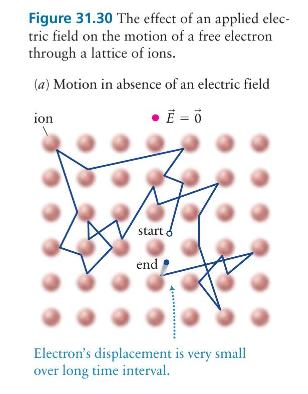
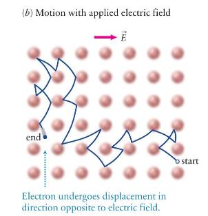
(a) Does the electric field do work on the electrons of Figure \(31.30 b\) as they accelerate between collisions?(b) On average, does the kinetic energy of the electrons increase as they drift through the lattice?(c) What do your answers to parts \(a\) and \(b\) imply about the energy in the
If the temperature of a metal is raised, the amplitude of the vibrations of the metal-lattice ions increases. (a) What effect, if any, do you expect these greater vibrations to have on the resistance of a piece of that metal? (b) What effect does running a current in a metal have on the temperature
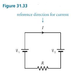
If \(\mathscr{E}_{1} Figure 31.33 reference direction for current I R www
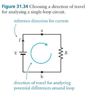
In the analysis of the circuit in Figure 31.34, we chose a clockwise reference direction for the current and a clockwise direction of travel. Redo the analysis using (a) a clockwise reference direction for the current and a counterclockwise direction of travel (b) a counterclockwise reference
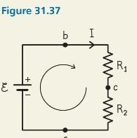
(a) In Figure 31.37, determine the potential difference between \(\mathrm{c}\) and \(\mathrm{b}\) by going counterclockwise from c to b.(b) For \(\mathscr{E}=9 \mathrm{~V}, R_{1}=10 \Omega\), and \(R_{2}=5 \Omega\), calculate \(V_{\mathrm{cb}}\) going counterclockwise from \(\mathrm{c}\) to
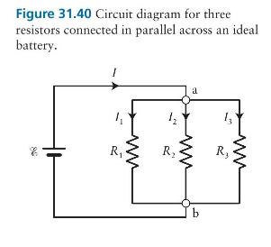
Let \(\mathscr{E}=9 \mathrm{~V}, R_{1}=3 \Omega, R_{2}=10 \Omega\), and \(R_{3}=5 \Omega\) in Figure 31.40. (a) What is the equivalent resistance of the three resistors?(b) What is the current in the battery? Figure 31.40 Circuit diagram for three resistors connected in parallel across an ideal
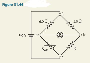
If \(R_{\text {var }}\) in Figure 31.44 is adjusted to a little less than \(12 \Omega\), what is the direction of the current in the light bulb? Figure 31.44 6.00 9.0 V aQ www 1.50 ww Rvar d R pb
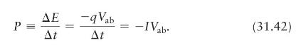
The SI units of power suggested by Eqs. 31.42 and 31.43 are \(A \cdot V\) and \(\mathrm{A}^{2} \cdot \Omega\), respectively. Show that these SI units are equivalent to the derived SI unit for power, the watt. -qVab P = -IVab (31.42) At At
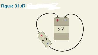
(a) In Example 31.12, how would the answer change if we had chosen a counterclockwise travel direction around the circuit?(b) At what rate is energy dissipated in the \(9-\mathrm{V}\) battery?Data from Example 31.12A \(9.0-\mathrm{V}\) and a \(6.0-\mathrm{V}\) battery are connected to each other
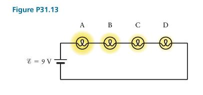
In Figure P31.13, bulb A is brighter than bulb B, B is brighter than \(\mathrm{C}\), and \(\mathrm{C}\) is brighter than \(\mathrm{D}\). Is it possible for the potential difference across bulb \(\mathrm{C}\) to be (a) \(3 \mathrm{~V}\)(b) \(2 \mathrm{~V}\) ? Figure P31.13 E=9V A B C D e e e
The bulbs A, B, C, and D are connected in series with a 12.0-V battery, and the steady current through bulb \(A\) is \(1.0 \mathrm{~A}\). Bulbs B and C, respectively, produce twice and three times as much light and thermal energy as bulb A and bulb D produces the same as bulb B. In \(2.0
Wires A, B, C, D, and E meet at a junction point O. The current in wire \(\mathrm{D}\) and \(\mathrm{E}\) is twice as in wire \(\mathrm{A}\) and four times as in \(\mathrm{C}\), respectively. The current in wire \(\mathrm{A}\) is \(4.2 \mathrm{~mA}\) into the junction, and the current in wire
(a) Given a copper wire with radius \(850 \mu \mathrm{m}\) carrying a uniform current of \(25 \mathrm{~mA}\), calculate the magnitude of electric field applied to this wire.(b) We have given two types of wire made up of copper and aluminum. If these wires are of the same length, radius, and carry
Given a copper wire of length \(100 \mathrm{~cm}\), radius \(0.8 \mathrm{~mm}\), and resistivity \(1.68 \times 10^{-8} \Omega \cdot \mathrm{m}\), find its resistance and current through the wire if connected to a \(20.0-\mathrm{V}\) battery. If the wire is stretched uniformly to 4 times its
To connect two devices, you need a \(40 \mathrm{~m}\) long copper wire. If the needed resistance of the wire is \(0.5 \Omega\), then what should be the diameter of the wire? If the voltage drop across the wire is \(10.0-\mathrm{V}\), then what is the current flow to each device? \(\left[ho_{\text
Determine the current density when 5.0 A of current is flowing through a copper wire of radius \(0.6 \mathrm{~mm}\). By what amount does current density change if the wire's radius is doubled?
Gauge is a term used to describe the size of a wire: The greater the gauge, the smaller the wire diameter. At room temperature, 6-gauge wire has a diameter of \(4.115 \mathrm{~mm}\), and 22-gauge wire has a diameter of \(0.644 \mathrm{~mm}\). For copper, how long would a wire of each gauge need to
You have a piece of copper wire and a piece of carbon rod, each \(1.5 \mathrm{~m}\) long and each having a cross-sectional area of \(8.0 \times 10^{-6} \mathrm{~m}^{2}\). When you connect the copper wire to the terminals of a \(9.0-\mathrm{V}\) battery, the current in the wire is \(I\). If you want
Three resistors are connected in series to a battery providing an emf of \(24 \mathrm{~V}\). If the resistances are \(R_{1}=8 \Omega, R_{2}=5 \Omega\), and \(R_{3}=3 \Omega\), what is the current that flows through the \(8-\Omega\) resistor (a) if the battery is ideal (b) if the battery has an
A nonideal battery connected to a resistor \(R_{1}\) in a circuit results in the current \(I_{1}\), if the same battery connected to a resistor \(R_{2}\) gives current \(I_{2}\). (a) What should be the value of \(R_{2}\) for which the internal resistance is zero? (b) If \(R_{2}=2 R_{1}\) and
List all the different resistances one can obtain using three resistors, each of value \(50 \Omega\). \(\cdot\)
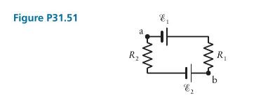
The potential difference between positions \(\mathrm{a}\) and \(\mathrm{b}\) in Figure P31.51 is \(6 \mathrm{~V}\), and \(R_{1}=4.0 \Omega, \mathscr{E}_{1}=10.0 \mathrm{~V}\), and \(\mathscr{E}_{2}=5.0 \mathrm{~V}\). What is the value of the resistance \(R_{2}\) ? Im Figure P31.51 R a b R
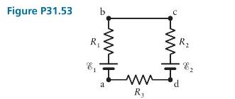
For the circuit shown in Figure P31.53, calculate (a) the magnitude and direction of the current (b) the potential differences Vab,Vbc,VcdVab,Vbc,Vcd, and VdaVda. Use these values: R1=4.0Ω,R2=2.0Ω,R3=6.0Ω,E1=4 VR1=4.0Ω,R2=2.0Ω,R3=6.0Ω,E1=4 V, and
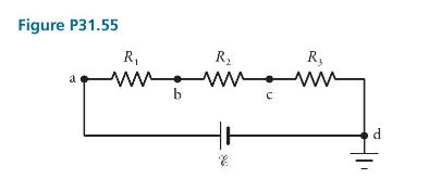
(a) What is the equivalent resistance of the circuit in Figure P31.55? Use the values \(R_{1}=10 \Omega, R_{2}=60 \Omega\), and \(R_{3}=5 \Omega\).(b) What is the current in the circuit? Assume \(\mathscr{E}=15 \mathrm{~V}\).(c) The electric potential at location \(\mathrm{d}\) is defined to be 0 ,
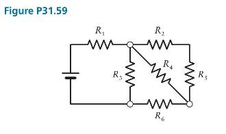
What is the equivalent resistance of the circuit in Figure P31.59? Use the values \(R_{1}=4.0 \Omega, R_{2}=2.0 \Omega\), \(R_{3}=1.0 \Omega, R_{4}=3 \Omega, R_{5}=1.0 \Omega\), and \(R_{6}=2.5 \Omega\). Figure P31.59 R www R www R www RA R5 R6
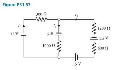
In Figure P31.67, calculate the magnitudes of currents \(I_{1}\), \(I_{2}\), and \(I_{3}\). Figure P31.67 300 www 12 V 12 1200 9V 1.5 V 1000 (2 600 02 1.5 V
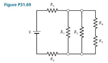
In Figure P31.69, calculate(a) the equivalent resistance of the circuit (b) the magnitude of the current through each resistor. Use these values: \(R_{1}=1.2 \Omega, R_{2}=2.0 \Omega\), \(R_{3}=2.0 \Omega, R_{4}=1.0 \Omega, R_{5}=3.0 \Omega, R_{6}=1.0 \Omega\), and \(\mathscr{E}=12 \mathrm{~V}\).
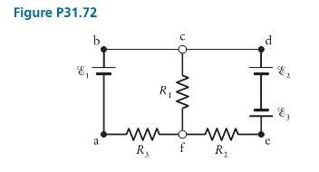
In Figure P31.72, \(\mathscr{E}_{1}=5.0 \mathrm{~V}, \mathscr{E}_{2}=5.0 \mathrm{~V}, \mathscr{E}_{3}=1.5 \mathrm{~V}\), \(R_{1}=50 \Omega, R_{2}=50 \Omega\), and \(R_{3}=50 \Omega\). What are(a) the current in each branch of the circuit (b) the potential differences \(V_{\mathrm{ab}},
Three resistances \(R, 2 R\), and \(3 R\) are connected in parallel in an electric circuit. Find the ratio of energy dissipation in \(R, 2 R\), and \(3 R\).
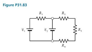
(a) Determine the current through and the potential difference across each resistor in Figure P31.83. Assume that \(R_{1}=R_{2}=R_{3}=R_{4}=3.0 \Omega, \quad \mathscr{E}_{1}=9.0 \mathrm{~V}\), and \(\mathscr{E}_{2}=4.5 \mathrm{~V}\).(b) At what rate is energy dissipated in each resistor?(c) What is
The current through a \(60-\mathrm{W}\) light bulb is \(2 \mathrm{~A}\) when connected to a nonideal battery with \(\mathrm{emf} \mathscr{E}=120 \mathrm{~V}\). Determine the bulb's resistance and internal resistance of the battery.
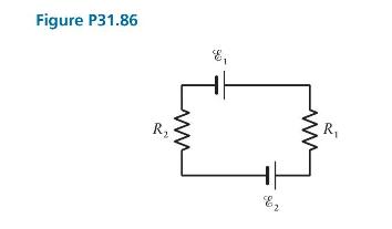
If the rate at which energy is dissipated by resistor 1 in Figure P31.86 is \(2.5 \mathrm{~W}\), and \(R_{1}=10 \Omega, \mathscr{E}_{1}=12 \mathrm{~V}\), and \(\mathscr{E}_{2}=6 \mathrm{~V},\) (a) what is the value of \(R_{2}\) ?(b) At what rate is energy dissipated in resistor 2?(c) Which battery
We have two types of wire made up of copper and aluminum. (a) If these wires are of same length, radius, and carry same current, which wire has higher rate of energy loss? (b) For same rate of energy loss, length, and radius for both types of wires, calculate the current in aluminum wire, if \(15
Consider a strip of material that has a rectangular crosssection with height \(310 \mu \mathrm{m}\) and width \(4.2 \mathrm{~mm}\) and which carries a uniform current of \(5.5 \mathrm{~mA}\).(a) What is the current density in the strip?(b) If the number density of the charge carrier (conduction
Calculate the mean free time \(\tau\) between the collisions for the conduction electron in copper. \(\left[n=8.49 \times 10^{28} \mathrm{~m}^{-3}\right.\), \(\left.ho_{\mathrm{Cu}}=1.68 \times 10^{-8} \Omega \cdot \mathrm{m}\right]\)
Given a wire of length \(5.5 \mathrm{~m}\) and radius \(1.2 \mathrm{~mm}\), find the type of material it is made up of if it carries a current of \(1.31 \mathrm{~A}\) and dissipates electrical energy at the rate of \(55.0 \mathrm{~mW}\).
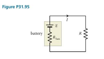
The battery in Figure P31.95 has internal resistance \(R_{\text {batt }}=4.0 \Omega\) and maintains an \(\operatorname{emf} \mathscr{E}=12.0 \mathrm{~V}\). What is the resistance \(\mathrm{R}\) of the resistor connected in series with the battery if the current through the circuit is \(0.5
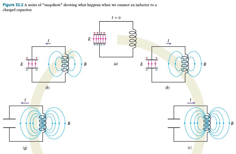
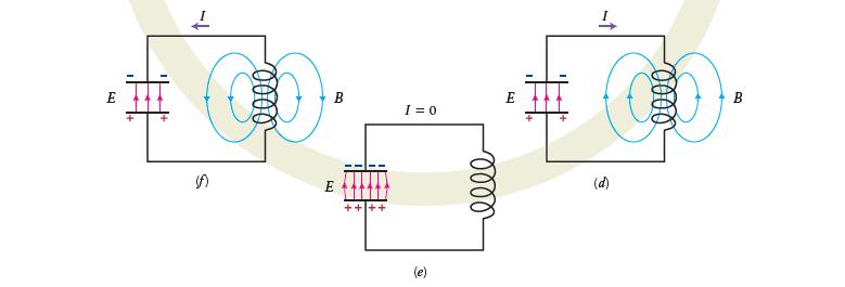
(a) Just before the inductor is connected to the charged capacitor, what type of energy is contained in the system comprising the two elements? (b) Once the two elements are connected to each other, what happens to that energy? (c) Once the capacitor is completely discharged, in what form is the
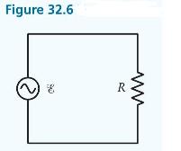
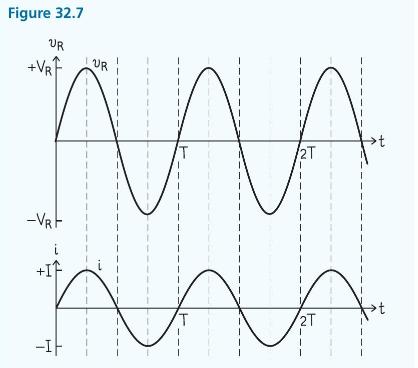
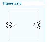
(a) Is energy dissipated in the resistor in the circuit of Figure 32.6?(b) If so, why doesn't the amplitude of the oscillations of \(v_{R}\) and \(i\) (shown in Figure 32.7) decrease with time? Figure 32.6 www R
Construct a phasor diagram for the time dependent current and potential difference at \(t=0\) in the AC source-resistor circuit of Figure 32.6. Figure 32.6 www E 90 R
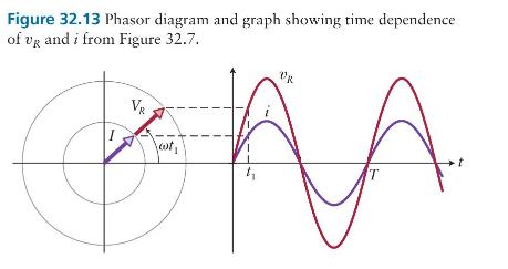
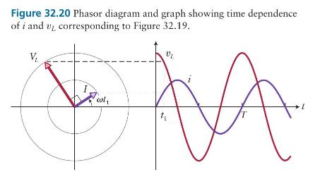
What are the initial phases for the phasors in Figures 32.13 and 32.20? Figure 32.13 Phasor diagram and graph showing time dependence of VR and i from Figure 32.7. VR DR t T
Is a piece of \(n\)-type silicon positively charged, negatively charged, or neutral?
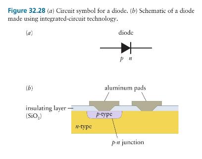
In the diode of Figure \(32.28 a\), which way do holes travel? Which way do electrons travel? Figure 32.28 (a) Circuit symbol for a diode. (b) Schematic of a diode made using integrated-circuit technology. (a) (b) insulating layer (SiO2) diode pn aluminum pads p-type n-type p-n junction
Suppose a sinusoidally varying potential difference is applied across a diode connected in series with a resistor. Sketch the potential difference across the diode as a function of time, and then, on the same graph, sketch the current in the resistor as a function of time.
In a bipolar transistor, what relationship, if any, exists among \(I_{b}, I_{c}\), and the emitter current \(I_{e}\) ?
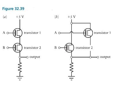
Circuit diagrams for two logic gates are shown in Figure 32.39. Which is the AND gate, and which is the OR gate? Explain briefly how each one works. Figure 32.39 (a) +5 V (b) +5 V A o transistor 1 A C transistor 1 transistor 2 Bo transistor 2. output O output
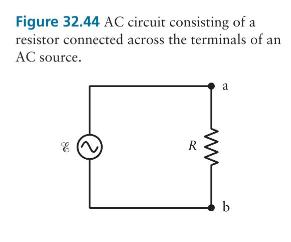
(a) In Figure 32.44, is the potential at point a higher or lower than the potential at \(\mathrm{b}\) when the current direction is clockwise through the circuit?(b) If we define such a current to be positive, is \(\mathscr{E}\) positive or negative? Express \(v_{R}\) in terms of the potential at a
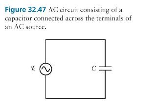
As in the \(L C\) circuit, the current in the circuit of Figure 32.47 oscillates. If we think of \(v_{C}\) as corresponding to the position of the simple harmonic oscillator, what property of the circuit of Figure 32.47 corresponds to the velocity of the oscillator? Figure 32.47 AC circuit
For the three circuits discussed in this section (AC source with resistor, capacitor, or inductor), sketch for a given emf amplitude (a) the resistance or reactance as a function of angular frequency \(\omega\) (b) the current amplitude in the circuit as a function of \(\omega\). Explain the
Suppose you need to add two potential differences that are oscillating at different angular frequencies-say, \(2 \sin (\omega t)\) and \(3 \cos (2 \omega t)\). Can you use the phasor method described above to determine the sum? Why or why not?
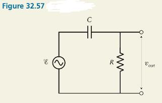
Interchange the resistor and the capacitor in Figure 32.57, and then show that the high-pass filter becomes a low-pass filter. Figure 32.57 C www R Vos out
(a) Calculate the maximum potential difference across each of the three circuit elements in Example 32.10.(b) Is the sum of the amplitudes \(V_{R}, V_{L}\), and \(V_{C}\) equal to the amplitude of the source emf? Why or why not?Data from Example 32.10Consider an RLC circuit, such as the one shown
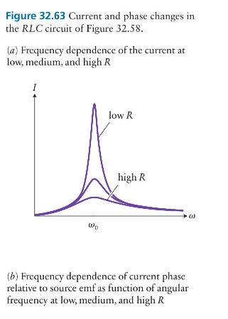
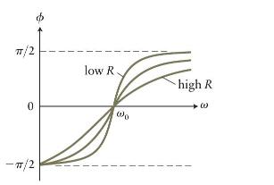
How does the resonance curve in Figure 32.63 change if the value of \(C\) or \(L\) is changed? Figure 32.63 Current and phase changes in the RLC circuit of Figure 32.58. (a) Frequency dependence of the current at low, medium, and high R I W low R high R (1) (b) Frequency dependence of current phase
In an \(R L C\) series circuit, you measure \(V_{R}=4.9 \mathrm{~V}, V_{L}=6.7 \mathrm{~V}\), and \(V_{C}=2.5 \mathrm{~V}\). Is the angular frequency of the \(\mathrm{AC}\) source above or below resonance?
Calculate the rate \(P_{\mathrm{av}}\) at which energy is dissipated in the \(R L C\) series circuit of Example 32.10.Data from Example 32.10Consider an RLC circuit, such as the one shown in Figure 32.58. The source emf has amplitude \(160 \mathrm{~V}\) and frequency \(60 \mathrm{~Hz}\). The
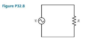
If the circuit in Figure P32.8 operates at \(50 \mathrm{~Hz}\) with \(\mathscr{E}_{\max }=120 \mathrm{~V}\) and \(R=15.0 \Omega\), how much energy is dissipated in the resistor in \(1.5 \mathrm{~s}\) ? Figure P32.8 www R
In a circuit consisting of a \(2 \mathrm{k} \Omega\) resistor connected in series with a \(50 \mathrm{mH}\) inductor, the amplitude of the emf is \(\mathscr{E}_{\max }=20 \mathrm{~V}\), and a \(20-\mathrm{kHz}\) signal is applied. Find impedance, current, phase angle, and potential differences
The reactance of a \(10-\mu \mathrm{F}\) capacitor is \(X_{C}=200 \Omega\). What is the angular frequency of the current through the capacitor?
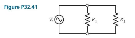
Figure P32.41 shows resistors \(R_{1}=10.0 \Omega\) and \(R_{2}=20.0 \Omega\) connected in parallel to an AC source.(a) If the maximum current in the circuit is \(12 \mathrm{~A}\), what is the amplitude \(\mathscr{E}_{\max }\) of the AC source?(b) If the source emf peaks at \(t=0\), and the
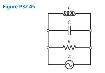
In the parallel circuit of Figure P32.45, the current amplitude is the same through the inductor branch, the capacitor branch, and the resistor branch. If \(L=0.36 \mathrm{mH}\) and \(\mathrm{C}=1.0 \mu \mathrm{F}\), what are the source angular frequency and the resistance \(R\) ? Figure P32.45 L
For a given series RLC circuit, draw the variation of \(X_{L}\), \(X_{C}\), and impedance with frequency.
For a given series RLC circuit, draw the variation of phase angle with frequency.
For a given series RLC circuit, draw the variation of impedance and current with frequency.
A circuit consists of an AC source wired in series to a \(1500-\Omega\) resistor and a \(1.5-\mu \mathrm{F}\) capacitor. For a source emf amplitude \(\mathscr{E}_{\max }=800.0 \mathrm{~V}\), calculate the phase constant \(\phi\) and the amplitudes \(V_{C}\) and \(V_{R}\) if the source frequency
For a series RLC circuit, charge at time \(t\) is given as \(q(t)=Q e^{-R t / 2 L} \cos \left(\omega^{\prime} t+\phi\right)\), where \(Q\) is the amplitude at time \(t=0\). If \(R=2 \Omega, C=2.3 \mu \mathrm{F}\) and \(L=15 \mathrm{mH}\), find the time at which the amplitude of the charge
An AC source with \(\mathscr{E}_{m}=220 \mathrm{~V}\) AC has a frequency of \(50.0 \mathrm{~Hz}\) and produces the same maximum current in two series circuits. Each circuit contains a \(160-\Omega\) resistor. Circuit 1 contains a \(5.6-\mu \mathrm{F}\) capacitor, and circuit 2 contains an inductor.
In problem 50, how many oscillations are completed within the time at which the amplitude of the charge oscillations in the circuit will be \(40 \%\) of its initial value?Data from Problem 50For a series RLC circuit, charge at time \(t\) is given as \(q(t)=Q e^{-R t / 2 L} \cos
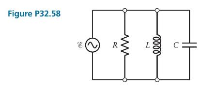
(a) What can you say, at all instants, about \(v_{R}, v_{C}\), and \(v_{L}\) in the parallel circuit of Figure P32.58?(b) Construct a phasor diagram for \(V_{R}, V_{C}, V_{L}\), and \(\mathscr{E}\) and a phasor diagram for \(i_{R}, i_{C}\), and \(i_{L}\).(c) What is the current in the source?(d)
Two AC potential differences \(v_{1}=V_{1} \sin \left(\omega t+\phi_{1}\right)\) and \(v_{2}=V_{2} \sin \left(\omega t+\phi_{2}\right)\) are added according to\[ \begin{aligned} v_{\text {sum }} & =V \sin (\omega t+\phi)=v_{1}+v_{2} \\ & =V_{1} \sin \left(\omega t+\phi_{1}\right)+V_{2} \sin
A series RLC circuit consists of \(R=10 \Omega, L=0.6 \mathrm{H}\), and \(C=10 \mu \mathrm{F}\). Determine the impedance at resonant frequency, \(10 \mathrm{~Hz}\) below resonant frequency, and \(10 \mathrm{~Hz}\) above resonant frequency. Explain the results.
An inductor resonates at \(2 \mathrm{kHz}\) when placed in series with a \(1.80-\mu \mathrm{F}\) capacitor. When driven at that resonant angular frequency, an AC source for which \(\mathscr{E}_{\text {max }}=180.0 \mathrm{~V}\) produces a \(0.3-\mathrm{A}\) current in the circuit. What is the
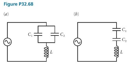
In Figure P32.68, \(C_{1}=1.00 \mu \mathrm{F}, C_{2}=2.00 \mu \mathrm{F}\), and \(L=\) \(47.0 \mathrm{mH}\). Which circuit has the lower resonant angular frequency, and what is that resonant angular frequency? Figure P32.68 (a) C C 0000 L (b) eeee THI C L C
An RLC circuit consists of a \(220-\Omega\) resistor, a \(3.3-\mu \mathrm{F}\) capacitor, and a \(3.9-\mathrm{mH}\) inductor. The circuit is connected to a power outlet that has a peak emf of \(150 \mathrm{~V}\) and oscillates at \(200 \mathrm{~Hz}\). What is the average rate at which energy is
A given capacitor of capacitance \(3.5 \mu \mathrm{F}\) is charged to \(65 \mathrm{~V}\). The charging battery is then disconnected and a \(15-\mathrm{mH}\) inductor is connected in series with this capacitor so that \(L C\) oscillations occur. Assume that there is no resistance in the circuit,
(a) Corresponding to each step in Figure \(32.2(a)-(b)\), draw bar graphs for stored magnetic and electric energies.(b) What should be next time \(t_{2}\) when, again, \(U_{E}=0.5 U_{E, \max }\) ? I=0 Figure 32.2 A series of "snapshots" showing what happens when we connect an inductor to a charged
An AC circuit with a \(240-\mathrm{V}\) peak emf has a \(30.0-\Omega\) resistor connected in series to a capacitor for which the capacitive reactance is \(X_{C}=60.0 \Omega\).(a) What is the phase constant?(b) What is the average rate at which energy is dissipated in the circuit?(c) If the
At time \(t=0\), an LC oscillator begins to oscillate when the capacitor has its maximum charge. Assume the resistance to be zero in the circuit. If \(L=30 \mathrm{mH}\) and \(C=2.5 \mu \mathrm{F}\), find the first time at which the electromagnetic energy of the oscillator is shared equally between
An \(R L C\) series circuit consists of a \(450-\Omega\) resistor, a \(3.00-\mathrm{mF}\) capacitor, and a \(1.00-\mathrm{H}\) inductor. The circuit is driven by a power source that oscillates at \(20.0 \mathrm{~Hz}\) and has an \(\mathscr{E}_{\text {rms }}\) value of \(60.0 \mathrm{~V}\). The
A solenoid can be treated as a series \(R L\) circuit. If such a cylindrical solenoid driven by a \(60-\mathrm{Hz}, 120-\mathrm{V} \mathrm{AC}\) source has 1200 turns of \(2 \mathrm{~cm}\) radius wrapped around a \(30-\mathrm{cm}-\) long core, and a resistance of \(2 \Omega\), what is the phase
Find the potential difference \(v_{X}(t)\), its amplitude \(V_{X}\), and current \(i_{X}(t)\), its amplitude \(I_{X}(X=R, C, L)\), if you are given a(a) purely resistive load with resistance \(R=100 \Omega\),(b) purely capacitive load with \(C=20 \mu \mathrm{F}\), and(c) purely inductive load with
An \(R L C\) series circuit containing a \(30.0-\Omega\) resistor, a \(7.5-\mathrm{mH}\) inductor, and a \(10-\mu \mathrm{F}\) capacitor is driven by an \(\mathrm{AC}\) source operating at \(1200 \mathrm{~Hz}\). If the source amplitude is \(\mathscr{E}_{\max }=180.0 \mathrm{~V}\), determine the
Showing 100 - 200
of 4962
1
2
3
4
5
6
7
8
9
10
11
12
13
14
15
Last
Step by Step Answers