New Semester
Started
Get
50% OFF
Study Help!
--h --m --s
Claim Now
Question Answers
Textbooks
Find textbooks, questions and answers
Oops, something went wrong!
Change your search query and then try again
S
Books
FREE
Study Help
Expert Questions
Accounting
General Management
Mathematics
Finance
Organizational Behaviour
Law
Physics
Operating System
Management Leadership
Sociology
Programming
Marketing
Database
Computer Network
Economics
Textbooks Solutions
Accounting
Managerial Accounting
Management Leadership
Cost Accounting
Statistics
Business Law
Corporate Finance
Finance
Economics
Auditing
Tutors
Online Tutors
Find a Tutor
Hire a Tutor
Become a Tutor
AI Tutor
AI Study Planner
NEW
Sell Books
Search
Search
Sign In
Register
study help
physics
classical dynamics of particles
System Dynamics 3rd edition William Palm III - Solutions
For the geared system shown in Figure, assume that shaft inertias and the gear inertias l1, l2, and I3, are negligible. The motor and load inertias in kg-m2 areI4 = 0.03 I5 = 0.15The speed ratios are ω1/ ω2 = ω2/ ω3 =1.6 Derive the system model in
For the geared system discussed in Problem 3.23, shown in Figure, the inertias are given in kg-m2 asI1 = 10-3I2 = 3.84 x 10⁻³I3 = 0.0148I4 = 0.03I5 = 0.15The speed ratios areω1/ ω2 = ω2/ ω3 = 1.6Derive the system model in terms of the speed ω3,
The geared system shown in Figure P3.25 is similar to that used in some vehicle transmissions. The speed ratios (which arc the ratios of the gearradii) are ω2/ω1 = 3 ω3/ω2 = 3/5 ω4/ω3 = 13/11 a. Determine the overall speed ratio
Consider the rack-and-pinion gear shown in Figure. Use the free-body diagram method to obtain the expression for the acceleration in terms of the given quantities: R, T, m, and I.
For the conveyor system shown in Figure, the reducer reduces the motor speed by a factor of 2:1. The motor inertia is I1 = 0.003 kg-m2. Discount the inertias of the reducer and the tachometer, which is used to measure the speed for control purposes. Ignore the inertias of the two sprockets, the
The lead screw (also called a power screw or a jack screw) is used to convert the rotation of a motor shaft into a translational motion of the mass m (see Figure). For one revolution of the screw, the mass translates a distance L (called the screw lead). As felt on the motor shaft, the translating
At time t = 0, the operator of the road roller disengages the transmission so that the vehicle rolls down the incline (see Figure). Determine an expression for the vehicle's speed as a function of time. The two rear wheels weigh 500 lb each and have a radius of 4 ft. The front wheel weighs 800 lb
For the mass shown in Figure 3.1.3b, m = 10 kg, ( = 25°, v(0) = 2 m/s, and μ = 0.3. Determine whether the mass comes to rest if (a) ft = 100 N and (b) f1 = 50 N. If the mass comes to rest, compute the time at which it stops.
Derive the equation of motion of the block of mass m1 in terms of its displacement x (see Figure). The friction between the block and the surface is negligible. The pulley has negligible inertia and negligible friction. The cylinder has a mass m2 and rolls without slipping.
Assume the cylinder in Figure rolls without slipping. Neglect the mass of the pulleys and derive the equation of motion of the system in terms of the displacement x.
A conveyor drive system to produce translation of the load is shown in Figure. The reducer is a gear pair that reduces the motor speed by a factor of 10:1. The motor inertia is I = 0.002 kg m2. The reducer inertia as felt on the motor shaft is I2 = 0.003 kg.m2. Neglect the inertia of the
A person pushes a roller of radius R and inertia mR2/2, with a force f applied at an angle of cp to the horizontal (see Figure). The roller weighs 800 N and has a diameter of 0.4 m. Assume the roller does not slip. Derive the equation of motion in terms of(a) The rotational velocity co of the
A slender rod l .4 m long and of mass 20 kg is attached to a wheel of radius 0.05 m and negligible mass, as shown in Figure. A horizontal force f is applied to the wheel axle. Derive the equation of motion in terms of θ. Assume the wheel does not slip.
A slender rod l .4 m long and of mass 20 kg is attached to a wheel of mass 3 kg and radius 0.05 m, as shown in Figure. A horizontal force / is applied to the wheel axle. Derive the equation of motion in terms of 6. Assume the wheel does not slip.
Consider the rolling cylinder treated in Example 3.4.1 and shown in Figure. Assume now that the no-slip condition is not satisfied, so that the cylinder slips while it rolls. Derive expression for the translational acceleration aG and the angular acceleration a. The coefficient of dynamic friction
A hoop of mass m and radius r starts from rest and rolls down an incline at an angle θ. The hoop's inertia is given by IG = mr2. The static friction coefficient is μs. Determine the acceleration of the center of mass aG and the angular acceleration a. Assume that the hoop rolls without bouncing
The scale shown in Figure measures the weight mg of an object placed on the scale, by using a counterweight of mass mc. Friction in the pivot point at A causes the pointer to eventually come to rest at an angle θ, which indicates the measured value of the weight mg. The angle B has a
A particle of mass m = 19 kg slides down a frictionless ramp starting from rest Suppose that 0 = 30°, L = 5 m, and H = 2 m. Compute the distance D of the impact point.
A single link of a robot arm is shown in Figure. The arm mass is m and its center of mass is located a distance L from the joint, which is driven by amotor torque Tm through two pairs of spur gears. We model the arm as a pendulum with a concentrated mass m. Thus we take the arm's moment of inertia
It is required to determine the maximum acceleration of the rear-wheel-drive vehicle shown in Figure. The vehicle mass is 1700 kg, and its dimensions are LA = 1.2 m, LB = 1.1m, and H = 0.5m. Assume that each front wheel experiences the same reaction force NA/2. Similarly, each rearwheel experiences
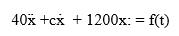
Figure illustrates a pendulum with a base that moves horizontally. This is a simple model of an overhead crane carrying a suspended load with cables. The load mass is m, the cable length is L, and the base acceleration is a(t). Assuming that the cable acts like a rigid rod, derive the equation of
Figure illustrates a pendulum with a base that moves. The base acceleration is a(t). Derive the equation of motion in terms of θ with a(t) as the input. Neglect the mass of the rod.
The overhead trolley shown in Figure is used to transport beams in a factory. The beam is rectangular, with a length of L. It is desired to limit the trolley horizontal acceleration a so that the beam does not swing too much. The beam starts from rest with θ(0) = 0. (a) Use a small
The analysis of the personal transporter in Example 3.5.6 assumed that the driving force / was the given input. Instead, model the system with the assumption that the input is the total torque Tw applied by the motor to the wheel-axle unit. The wheel radius is R. Obtain the equations of motion in
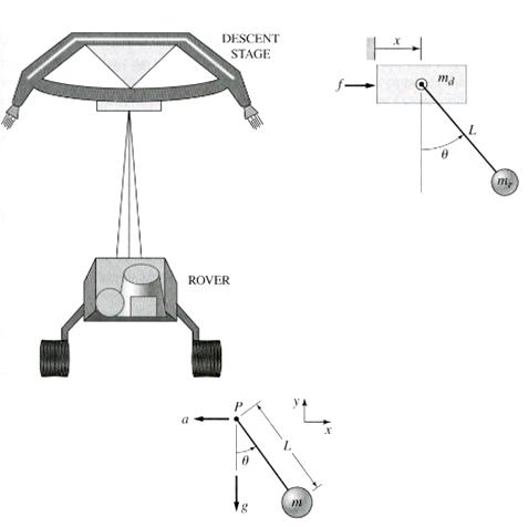
The "sky crane" shown on the text cover was a novel solution to the problem of landing the 2000 lb Curiosity rover on the surface of Mars. Curiosity hangs from the descent stage by 60-foot-long nylon tethers (Figure). The descent stage uses its thrusters to hover as the rover is lowered to the
A particle of mass m slides down a frictionless ramp starting from rest. The lengths L and H and the angle 0 are given. Derive an expression for the distance D of the impact point.
Radar tracks the flight of a projectile. At time the radar measures the horizontal component vx(t) and the vertical component vy(t) of the projectile's velocity and its range R(t) and elevation ((t). Are these measurements sufficient to compute the horizontal distance D from the radar to the launch
A motor supplies a moment M to the pulley of radius R1. A belt connects this pulley to pulley A. Pulleys A and B form a rigid body with a common hub. Ignore the inertias of the three pulleys. Determine the acceleration of the mass m in terms of M, m, R1, R2, and R3.
Compute the translational spring constant of a particular steel helical coil spring, of the type used in automotive suspensions. The coil has six turns. The coil diameter is 4 in., and the wire diameter is 0.5 in. For the shear modulus, use G = 1.7 x 10⁹ lb/ft2.
Compute the equivalent tensional spring constant of the stepped shaft arrangement shown in Figure. For the shaft material, G = 8 x 10¹⁰ N/m2.
Plot the spring force felt by the mass shown in Figure as a function of the displacement x. When x = 0, spring 1 is at its free length. Spring 2 is at its free length in the configuration shown.
Calculate the expression for the natural frequency of the system shown in Figure. Disregard the pulley mass.
Obtain the expression for the natural frequency of the system shown in Figure. Assume small motions and disregard the pulley mass.
Obtain the expression for the natural frequency of the system shown in Figure. Discount the mass of the L-shaped arm.
A connecting rod having a mass of 3.6 kg is shown in Figure. It oscillates with a frequency of 40 cycles per minute when supported on a knife edge, as shown. Its mass center is located 0.15 m below the support. Calculate the moment of inertia about the mass center.
Calculate the expression for the natural frequency of the system shown in Figure.
For each of the systems shown in Figure, the input is the force f and the outputs are the displacements x1 and x2 of the masses. The equilibrium positions with f = 0 correspond to x1 = x2 = 0. Neglect any friction between the masses and the surface. Derive the equations of motion of the systems.
The mass m in Figure is attached to a rigid lever having negligible mass and negligible friction in the pivot. The input is the displacement x. When x and θ are zero, the springs are at their free length. Assuming that θ is small, derive the equation of motion for
In the pulley system shown in Figure, the input is the applied force f, and the output is the displacement x. Assume the pulley masses are negligible and derive the equation of motion.
In the spring arrangement shown in Figure, the displacement x is caused by the applied force f. Assuming the system is in static equilibrium, sketch the plot of f versus x. Determine the equivalent spring constant ke for this arrangement, where f = kex.
Figure illustrates a cylindrical buoy floating in water with a mass density (. Assume that the center of mass of the buoy is deep enough so that the buoy motion is primarily vertical. The buoy mass is m and the diameter is D. Archimedes' principle states that the buoyancy force acting on a floating
Figure shows the cross-sectional view of a ship undergoing rolling motion. Archimedes' principle states that the buoyancy force B acting on a floating object equals the weight of the liquid displaced by the object. The met center M is the intersection point of the line of action of the buoyancy
In the system shown in Figure, the input is the angular displacement ( of the end of the shaft, and the output is the angular displacement θ of the inertia I. The shafts have tensional stiffness's k1 and k2. The equilibrium position corresponds to ( = θ = 0. Derive the equation of motion and
In Figure, assume that the cylinder rolls without slipping. The spring is at its free length when x and y are zero,(a) Derive the equation of motion in terms of x, with y(t) as the input,(b) Suppose that m = 10 kg, R = 0.3 m, k = 1000 N/m, and that y(t) is a unit-step function. Solve for x(t) if
In Figure when x1 = x2 = 0 the springs are at their free lengths. Derive the equations of motion.
In Figure model the three shafts as mass less tensional springs. When θ1= θ2 = 0 the springs are at their free lengths. Derive the equations of motion with the torque T2 as the input.
In Figure when θ1 = θ2 = 0 the spring is at its free length. Derive the equations of motion, assuming small angles.
Consider the torsion-bar suspension shown in Figure 4.1.6. Assume that the torsion bar is a steel rod with a length of 4 ft and diameter 1.5 in. The wheel weighs 40 lb and the suspension arm is 2 ft long. Neglect the masses of the torsion bar and the suspension arm, and calculate the natural
For the system shown in Figure, suppose that k1 = k, k2 = k3 = 2k, and m1 = m2 = m. Obtain the equations of motion in terms of x1 and x2.
For the system shown in Figure, suppose that R2 = 2R1, m1 = m, and m2 = 2m. The two pulleys share a common hub and are welded together. Their total mass is m2 and total inertia is l2. Obtain the equations of motion in terms of x and θ.
In the arrangement shown in Figure, a cable is attached to the end of a cantilever beam. We will model the cable as a rod. Denote the translational spring constant of the beam by kb, and the translational spring constant of the cable by kc. The displacement x is caused by the applied force f.a. Are
For Figure, assume that the cylinder rolls without slipping and use conservation of energy to derive the equation of motion in terms of x.
For Figure, the equilibrium position corresponds to x = 0. Neglect the masses of the pulleys and assume that the cable is inextensible, and use conservation of energy to derive the equation of motion in terms of x.
For Figure, the equilibrium position corresponds to x = 0. Neglect the masses of the pulleys and assume that the cable is inextensible, and use conservation of energy to derive the equation of motion in terms of x.
Use the Rayleigh method to obtain an expression for the natural frequency of the system shown in Figure. The equilibrium position corresponds to x = 0.
For Figure, assume that the cylinder rolls without slipping and use the Rayleigh method to obtain an expression for the natural frequency of the system. The equilibrium position corresponds to x = 0.
Use the Rayleigh method to obtain an expression for the natural frequency of the system shown in Figure. The equilibrium position corresponds to x = 0.
Use an energy method to obtain the expression for the natural frequency of the system shown in Figure.
Determine the natural frequency of the system shown in Figure using Rayleigh's method. Assume small angles of oscillation.
Determine the natural frequency of the system shown in Figure using an energy method. The disk is a solid cylinder. Assume small angles of oscillation.
Use Rayleigh's method to calculate the expression for the natural frequency of the system shown in Figure. Assume small motions and neglect the pulley mass.
In the spring arrangement shown in Figure, the displacement x is caused by the applied force f. Assuming the system is in static equilibrium when x = 0 and that the angle θ is small, determine the equivalent spring constant ke for this arrangement, where / = kex.
Use Rayleigh's method to obtain the expression for the natural frequency of the system shown in Figure. Disregard the mass of the L-shaped arm.
Determine the natural frequency of the system shown in Figure using Rayleigh's method. Assume small angles of oscillation.
Figure shows an engine valve driven by an overhead camshaft. The rocker arm pivots about the fixed point O and the inertia of the arm about this point is Ir. The valve mass is mv and the spring mass is ms; its spring constant is ks. Let fc denote the force exerted on the rocker arm by the camshaft.
The vibration of a motor mounted on the end of a cantilever beam can be modeled as a mass-spring system. The motor weighs 30 lb, and the beam weighs 7 lb. When the motor is placed on the beam, it causes an additional static deflection of 0.8 in. Find the equivalent mass m and equivalent spring
The vibration of a motor mounted in the middle of a fixed-end beam can be modeled as a mass-spring system. The motor mass is 40 kg, and the beam mass is 13 kg. When the motor is placed on the beam, it causes an additional static deflection of 3 mm. Find the equivalent mass m and equivalent spring
The vibration of a motor mounted in the middle of a simply-supported beam can be modeled as a mass-spring system. The motor mass is 30 kg, and the beam mass is 10 kg. When the motor is placed on the beam, it causes an additional static deflection of 2 mm. Find the equivalent mass m and equivalent
A certain cantilever beam vibrates at a frequency of 5 Hz when a 30 lb motor is placed on the beam. The beam weighs 7 lb. Estimate the beam stiffness k.
A 10-kg mass is attached to a 2 kg spring. The mass vibrates at a frequency of 20 Hz when disturbed. Estimate the spring stiffness k.
The static deflection of a cantilever beam is described byxy = P/(6EIA) y2 (3L - y)Where P is the load applied at the end of the beam, and xy is the vertical deflection at a point a distance y from the support (Figure). Obtain an expression for an equivalent mass located at the end of the beam.
Figure shows a winch supported by a cantilever beam at the stern of a ship. The mass of the winch is mw, the mass of the beam plus winch bracket and motor is mb. The object hoisted by the winch has a mass mb; the wire rope mass mr is assumed to be negligible compared to the other masses. Find the
For the system shown in Figure, assume that the resulting motion is small enough to be only horizontal, and determine the expression for the equivalent ke that relates the applied force f to the resulting displacement x.
A 50-kg block is placed on an inclined plane whose angle with the horizontal is 25°. The viscous friction coefficient between the block and the plane is c = 6 N s/m.(a) Derive the equation of motion,(b) Solve the equation of motion for the speed v(t) of the block, assuming that the block is
A certain mass-spring-damper system has the following equation of motion.Suppose that the initial conditions are zero and that the applied force f(t) is a step function of magnitude 5000. Solve for x(t) for the following two cases:(a) c = 680 (b) c = 400.
For each of the systems shown in Figure, the input is the force f and the outputs are the displacements x1 and x2 of the masses. The equilibrium positions with f = 0 correspond to x1 = x2 = 0. Neglect any friction between the masses and the surface. Derive the equations of motion of the
In Figure a motor supplies a torque T to turn a drum of radius R and inertia I about its axis of rotation. The rotating drum lifts a mass m by means of a cable that wraps around the drum. The drum's speed is ω. viscous tensional damping cT exists in the drum shaft. Neglect the mass of
Derive the equation of motion for the lever system shown in Figure P4.54, with the force f as the input and the angle θ as the output. The position θ = 0 corresponds to the equilibrium position when f = 0. The lever has an inertia / about the pivot. Assume small
In the system shown in Figure, the input is the displacement y and the output is the displacement x of the mass m. The equilibrium position corresponds to x = y = 0. Neglect any friction between the mass and the surface. Derive the equation of motion and find the transfer function X(s)/Y(s).
Figure a shows a Houdaille damper, which is a device attached to an engine crankshaft to reduce vibrations. The damper has an inertia Id that is free to rotate within an enclosure filled with viscous fluid. The inertia Ip is the inertia of the fan-belt pulley. Modeling the crankshaft as a tensional
Refer to Figure. Determine the relations between c, c1, and c2 so that the damper shown in part (c) is equivalent to (a) the arrangement shown in part (a), and the arrangement shown in part (b).a.b.
For the system shown in Figure, obtain the equation of motion in terms of θ. The disk is a solid cylinder. Assume small angles of oscillation.
Find the transfer function Z(s)X(s) for the system shown in Figure.
The two stepped solid cylinders in Figure consist of the same material and have an axial force f applied to them. Determine the equivalent translational spring constant for this arrangement.
Find the transfer function Y(s)X(s) for the system shown in Figure.
Find the transfer function Y(s)X(s) for the system shown in Figure.
The mass m in Figure is attached to a rigid rod having inertia I about the pivot and negligible pivot friction. The input is the displacement z. When z = θ = 0, the spring is at its free length. Assuming that θ is small, derive the equation of motion for θ
In the system shown in Figure, the input is the force f and the output is the displacement xA of point A. When x = xA the spring is at its free length. Derive the equation of motion.
In the system shown in Figure, the input is the displacement y and the output is the displacement x. When x = y = 0 the springs are at their free lengths. Derive the equation of motion.
Figure shows a rack-and-pinion gear in which a damping force and a spring force act against the rack. Develop the equivalent rotational model of the system with the applied torque T as the input variable and the angular displacement θ is the output variable. Neglect any twist in the
Figure shows a drive train with a spur-gear pair. The first shaft turns N times faster than the second shaft. Develop a model of the system including the elasticity of the second shaft. Assume the first shaft is rigid, and neglect the gear and shaft masses. The input is the applied torque T1. The
Assuming that θ is small, derive the equations of motion of the systems shown in parts (a) and (b) of Figure. When θ = 0 the systems are in equilibrium. Are the systems stable, neutrally stable, or unstable?a.b.
Assuming that θ is small, derive the equation of motion of the pendulum shown in Figure. The pendulum is in equilibrium when θ = 0. Is the system stable, neutrally stable, or unstable?
Assuming that θ is small, derive the equation of motion of the pendulum shown in Figure. The input is y(t) and the output is θ. The equilibrium corresponds to y = θ = 0, when the springs are at their free lengths. The rod inertia about the pivot is I.
A table with four identical legs supports a vertical force. The solid cylindrical legs are made of metal with E = 2 x 10¹¹ N/m2. The legs are 1 m in length and 0.03 m in diameter. Compute the equivalent spring constant due to the legs, assuming the table top is rigid.
Figure shows a quarter-car model that includes the mass of the seats (including passengers). The constants k3, and c3 represent the stiffness and damping in the seat supports. Derive the equations of motion of this system. The input is the road displacement y(t). The displacements are measured from
The top view of a solid door is shown in Figure. The door has a mass of 40 kg and is 2.1 m high, 1.2 m wide and 0.05 m thick. Its door closer has a tensional spring constant of 13.6 N-m/rad. The door will close as fast as possible without oscillating if the tensional damping coefficient c in the
A boxcar moving at 1.3 m/s hits the shock absorber at the end of the track (Figure). The boxcar mass is 18 000 kg;. The stiffness of the absorber is k = 73 000 N/m, and the damping coefficient is c = 88 000 N-s/m. Determine the maximum spring compression and the time for the boxcar to stop.
Showing 700 - 800
of 1327
1
2
3
4
5
6
7
8
9
10
11
12
13
14
Step by Step Answers
.png)
.png)
.png)
.png)
.png)
.png)
.png)
.png)
.png)
.png)
.png)
.png)
.png)
.png)
.png)
.png)
.png)
.png)
.png)
.png)
.png)
.png)
.png)
.png)
.png)
.png)
.png)
.png)
.png)
.png)
.png)
.png)
.png)
.png)
.png)
.png)
.png)
.png)
.png)
.png)
.png)
.png)
.png)
.png)
.png)
.png)
.png)
.png)
.png)
.png)
.png)
.png)
.png)
.png)
.png)
.png)
.png)
.png)
.png)
.png)
.png)
.png)
-1.png)
-2.png)
-3.png)
.png)
.png)
.png)
-1.png)
-2.png)
-1.png)
-2.png)
-3.png)
.png)
.png)
.png)
.png)
.png)
.png)
.png)
.png)
.png)
.png)
-1.png)
-2.png)
.png)
.png)
.png)
.png)
.png)

