New Semester
Started
Get
50% OFF
Study Help!
--h --m --s
Claim Now
Question Answers
Textbooks
Find textbooks, questions and answers
Oops, something went wrong!
Change your search query and then try again
S
Books
FREE
Study Help
Expert Questions
Accounting
General Management
Mathematics
Finance
Organizational Behaviour
Law
Physics
Operating System
Management Leadership
Sociology
Programming
Marketing
Database
Computer Network
Economics
Textbooks Solutions
Accounting
Managerial Accounting
Management Leadership
Cost Accounting
Statistics
Business Law
Corporate Finance
Finance
Economics
Auditing
Tutors
Online Tutors
Find a Tutor
Hire a Tutor
Become a Tutor
AI Tutor
AI Study Planner
NEW
Sell Books
Search
Search
Sign In
Register
study help
computer science
computer system architecture
Computer System Architecture 3rd Edition M. Morris Mano - Solutions
The program in a computer compares two unsigned numbers A and B by performing a subtraction A - B and updating the status bits. Let A = 01000001 and B = 10000100. a. Evaluate the difference and interpret the binary result. b. Determine the values of status bits C (borrow) and Z. c. List the
The program in a computer compares two signed numbers A and B by performing the subtraction A - B and updating the status bits. Let A = 01000001 and B = 10000100. a. Evaluate the difference and interpret the binary result. b. Determine the value of status bits S, Z, and V. c. List the
The content of the top of a memory stack is 5320. The content of the stack pointer SP is 3560. A two-word call subroutine instruction is located in memory at address 1120 followed by the address field of 6720 at location 1121. What are the content of PC, SP, and the top of the stack: a. Before the
What are the basic differences between a branch instruction, a call subroutine instruction, and program interrupt?
Give five examples of external interrupts and five examples of internal interrupts. What is the difference between a software interrupt and a subroutine call?
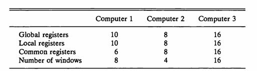
Three computers use register windows with the following characteristics. Determine the window size and the total number of registers in each computer. Global registers Local registers Common registers Number of windows Computer 1 10 10 6 8 Computer 2 8 +∞ ∞ ∞ 8 8 4 Computer 3 16 16 666 16 16
A computer responds to an interrupt request signal by pushing onto the stack the contents of PC and the current PSW (program status word). It then reads a new PSW from memory from a location given by an interrupt address symbolized by IAD. The first address of the service program is taken from
Examples of computers with variable instruction formats are IBM 370, VAX 11, and Intel 386. Compare the variable instruction formats of one of these computers with the fixed-length instruction format used in RISC I.
Give an example of a RISC I instructions that will perform the following operations. a. Decrement a register b. Complement a register c. Negate a registerd. Clear a register to 0 e. Divide a signed number by 4 f. No operation
Write the RISC I instructions in assembly language that will cause a jump to address 3200 if the Z (zero) status bit is equal to 1. a. Using immediate mode b. Using a relative address mode (assume that PC = 3400)
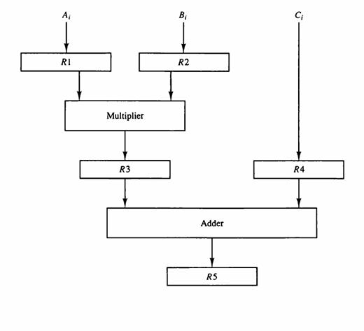
In certain scientific computations it is necessary to perform the arithmetic operation (Ai + Bi)(Ci + Di) with a stream of numbers. Specify a pipeline configuration to carry out this task. List the contents of all registers in the pipeline for i = 1 through 6.
Draw a space-time diagram for a six-segment pipeline showing the time it takes to process eight tasks.
Determine the number of clock cycles that it takes to process 200 tasks in a six-segment pipeline.
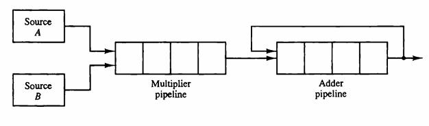
The pipeline of Fig. 9-2 has the following propagation times: 40 ns for the operands to be read from memory into registers R1 and R2, 45 ns for the signal to propagate through the multiplier, 5 ns for the transfer into R3, and 15 ns to add the two numbers into R5. a. What is the minimum clock
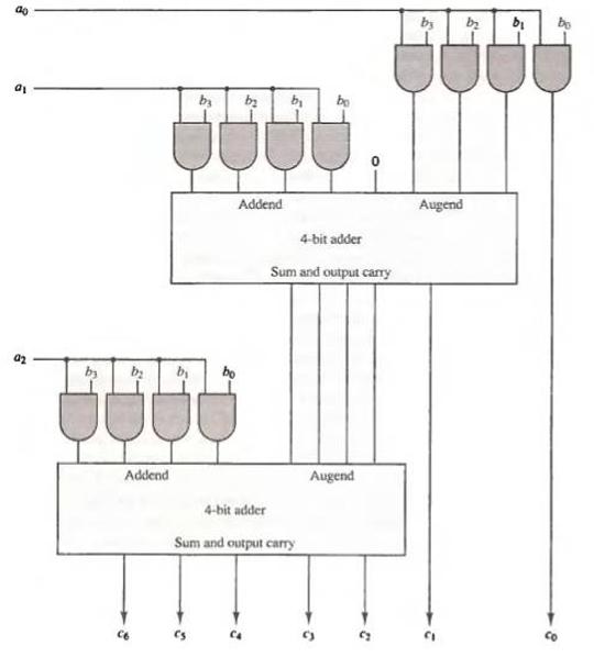
It is necessary to design a pipeline for a fixed-point multiplier that multiplies two 8-bit binary integers. Each segment consists of a number of AND gates and a binary adder similar to an array multiplier as shown in Fig. 10-10.a. How many AND gates are there in each segment, and what size of
A nonpipeline system takes 50 ns to process a task. The same task can be processed in a six-segment pipeline with a clock cycle of 10 ns. Determine the speedup ratio of the pipeline for 100 tasks. What is the maximum speedup that can be achieved?
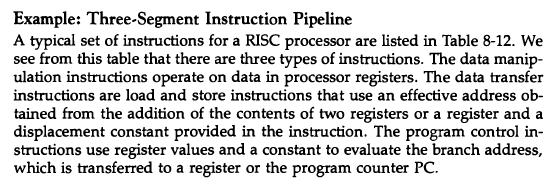
Give an example of a program that will cause data conflict in the three-segment pipeline of Sec. 9-5. Example: Three-Segment Instruction Pipeline A typical set of instructions for a RISC processor are listed in Table 8-12. We see from this table that there are three types of instructions. The data
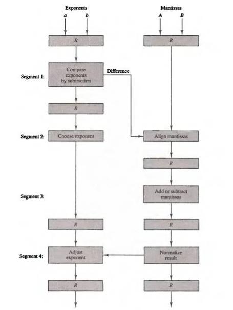
The time delay of the four segments in the pipeline of Fig. 9-6 are as follows: t1 = 50 ns, t2 = 30 ns, t3 = 95 ns, and t4 = 45 ns. The interface registers delay time tr - 5 ns. a. How long would it take to add 100 pairs of numbers in the pipeline? b. How can we reduce the total time to about
How would you use the floating-point pipeline adder of Fig. 9-6 to add 100 floating-point numbers X1 + X2 + X3 + … + X100?Fig. 9-6 Segment 1: Segment 3: Exponents Segment 4: Compare Segment 2: Choose exponent exponents by subtraction |||||| HOME Adjust Difference exponent Mantissas A Align
Give an example that uses delayed load with the three-segment pipeline of Sec. 9-5. Example: Three-Segment Instruction Pipeline A typical set of instructions for a RISC processor are listed in Table 8-12. We see from this table that there are three types of instructions. The data manip- ulation
Give an example of a program that will cause a branch penalty in the three-segment pipeline of Sec. 9-5. Example: Three-Segment Instruction Pipeline A typical set of instructions for a RISC processor are listed in Table 8-12. We see from this table that there are three types of instructions. The
Give an example that uses delayed branch with the three-segment pipeline of Sec. 9-5. Example: Three-Segment Instruction Pipeline A typical set of instructions for a RISC processor are listed in Table 8-12. We see from this table that there are three types of instructions. The data manip- ulation
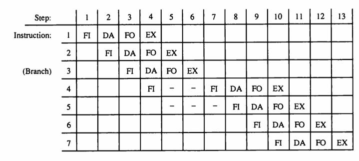
Consider the four instructions in the following program. Suppose that the first instruction starts from step 1 in the pipeline used in Fig. 9-8. Specify what operations are performed in the four segments during step 4. Fig. 9-8 Load ADD INC STORE R1-M[312] R2 R3 R3 + 1 M[314] R3 R2+ M[313]
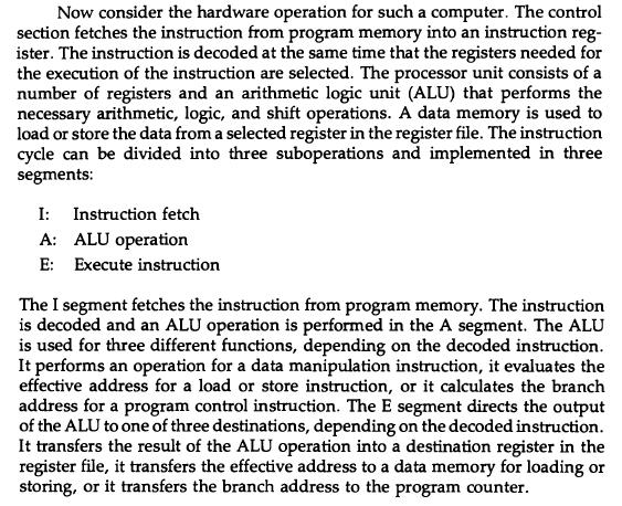
Formulate a six-segment instruction pipeline for a computer. Specify the operations to be performed in each segment.
Explain four possible hardware schemes that can be used in an instruction pipeline in order to minimize the performance degradation caused by instruction branching.
How many clock cycles does it take to process an inner product in the pipeline of Fig. 9-12 when used to evaluate the product of two 60 x 60 matrices? How many inner products are there, and how many clock cycles does it take to evaluate the product matrix?Fig. 9-12
Consider the multiplication of two 40 x 40 matrices using a vector processor. a. How many product terms are there in each inner product, and how many inner products must be evaluated? b. How many multiply-add operations are needed to calculate the product matrix?
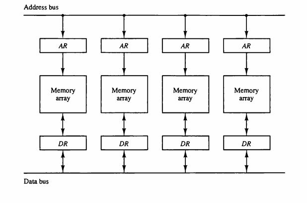
Assign addresses to an array of data of 1024 words to be stored in the memory described in Fig. 9-13.Fig. 9-13 Address bus Data bus AR Memory аптау DR AR Memory аптау DR AR Memory аптау DR AR Memory аптау DR
A weather forecasting computation requires 250 billion floating-point operations. The problem is processed in a supercomputer that can perform 100 megaflops. How long will it take to do these calculations?
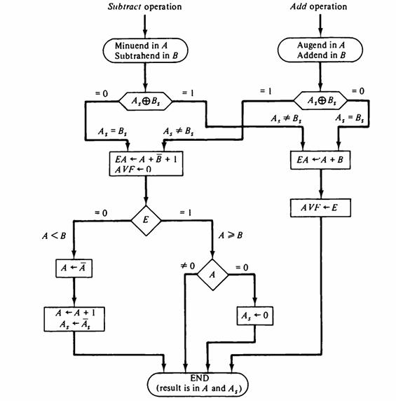
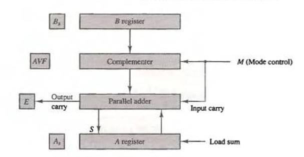
The complementer shown in Fig. 10-1 is not needed if instead of performing A + B̅ + 1 we perform B+ A̅ (B plus the 1's complement of A). Derive an algorithm in flowchart form for addition and subtraction of fixed-point binary numbers in signed-magnitude representation with the magnitudes
Consider a computer with four floating-point pipeline processors. Suppose that each processor uses a cycle time of 40 ns. How long will it take to perform 400 floating-point operations? Is there a difference if the same 400 operations are carried out using a single pipeline processor with a cycle
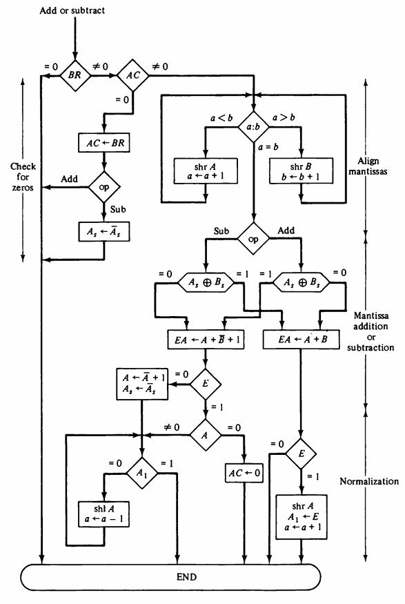
Mark each individual path in the flowchart of Fig. 10-2 by a number and then indicate the overall path that the algorithm takes when the following signed- magnitude numbers are computed. In each case give the value of AVF. The leftmost bit in the following numbers represents the sign bit. a. 0
Perform the arithmetic operations below with binary numbers and with negative numbers in signed-2's complement representation. Use seven bits to accommodate each number together with its sign. In each case, determine if there is an overflow by checking the carries into and out of the sign bit
Consider the binary numbers when they are in signed-2's complement representation. Each number has n bits: one for the sign and k = n - 1 for the magnitude. A negative number -X is represented as 2k + (2k - X), where the first 2k designates the sign bit and (2k - X) is the 2's complement of X. A
Formulate a hardware procedure for detecting an overflow by comparing the sign of the sum with the signs of the augend and addend. The numbers are in signed-2's complement representation.
a. Perform the operation (-9) + (-6)= -15 with binary numbers in signed-1's complement representation using only five bits to represent each number (including the sign). Show that the overflow detection procedure of checking the inequality of the last two carries fails in this case. b. Suggest a
Derive an algorithm in flowchart form for adding and subtracting two fixed- point binary numbers when negative numbers are in signed-1's complement representation.
Prove that the multiplication of two n-digit numbers in base r gives a product no more than 2n digits in length. Show that this statement implies that no overflow can occur in the multiplication operation.
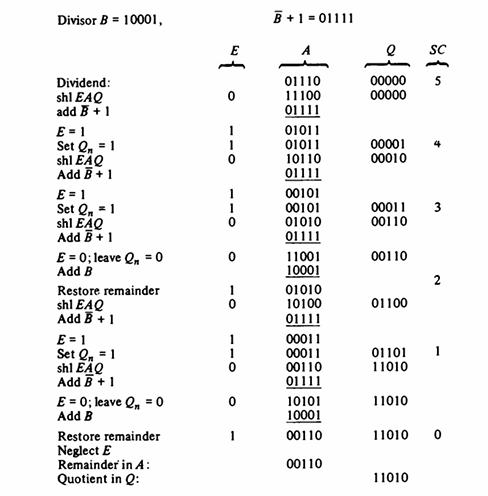
Show the contents of registers E, A, Q, and SC (as in Fig. 10-12) during the process of division of (a) 10100011 by 1011; (b) 00001111 by 0011. (Use a dividend of eight bits.)Fig. 10-12 Divisor B = 10001, Dividend: shl EAQ add B + 1 E=1 Set Q₁ = 1 shl EAQ Add B + 1 E = 1 Set Q₁ = 1 shl
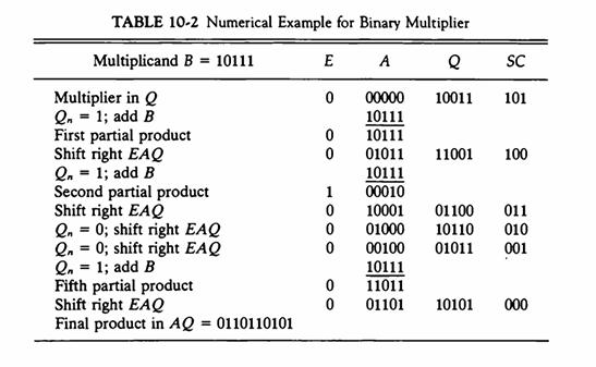
Show the contents of registers E, A, Q, and SC (as in Table 10-2) during the process of multiplication of two binary numbers, 11111 (multiplicand) and 10101 (multiplier). The signs are not included.Table 10-2 TABLE 10-2 Numerical Example for Binary Multiplier Multiplicand B = 10111 E A e SC 00000
Show that adding B after the operation A + B̅ + 1 restores the original value of A. What should be done with the end carry?
Why should the sign of the remainder after a division be the same as the sign of the dividend?
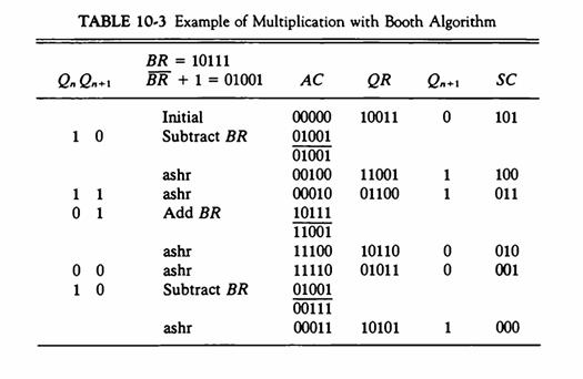
Show the step-by-step multiplication process using Booth algorithm (as in Table 10-3) when the following binary numbers are multiplied. Assume 5-bit registers that hold signed numbers. The multiplicand in both cases is +15. a. (+15) x (+13) b. (+15) x (-13)Table 10-3 TABLE 10-3 Example of
Design an array multiplier that multiplies two 4-bit numbers. Use AND gates and binary adders.
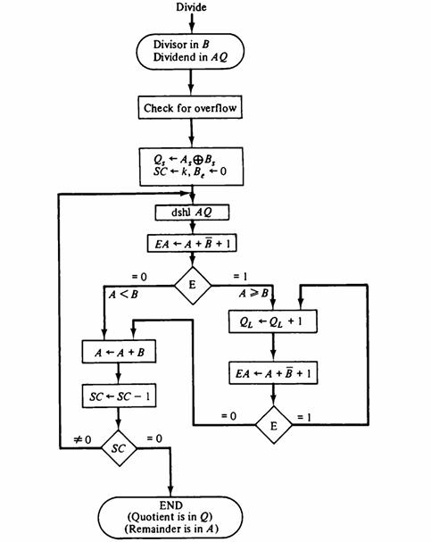
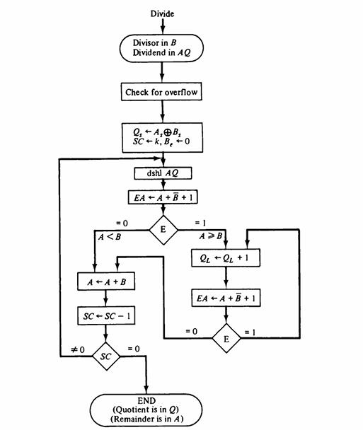
Derive an algorithm in flowchart form for the nonrestoring method of fixed- point binary division.
Derive an algorithm for evaluating the square root of a binary fixed-point number.
A binary floating-point number has seven bits for a biased exponent. The constant used for the bias is 64. a. List the biased representation of all exponents from -64 to +63.b. Show that a 7-bit magnitude comparator can be used to compare the relative magnitude of the two exponents. c. Show that
Let n be the number of bits of the mantissa in a binary floating-point number. When the mantissas are aligned during the addition or subtraction, the exponent difference may be greater than n - 1. If this occurs, the mantissa with the smaller exponent is shifted entirely out of the register. Modify
Derive an algorithm in flowchart form for the comparison of two signed binary numbers when negative numbers are in signed-2's complement representation: a. By means of a subtraction operation with the signed-2's complement numbers. b. By scanning and comparing pairs of bits from left to right.
The algorithms for the floating-point arithmetic operations in Sec. 10-5 neglect the possibility of exponent overflow or underflow. a. Go over the three flowcharts and find where an exponent overflow may occur. b. Repeat (a) for exponent underflow. An exponent underflow occurs if the exponent is
Repeat Prob. 10-18 for signed-magnitude binary numbers.Prob. 10-18Derive an algorithm in flowchart form for the comparison of two signed binary numbers when negative numbers are in signed-2's complement representation: a. By means of a subtraction operation with the signed-2's complement
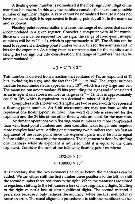
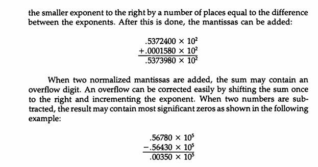
The procedure for aligning mantissas during addition or subtraction of floating-point numbers can be stated as follows: Subtract the smaller exponent from the larger and shift right the mantissa having the smaller exponent a number of places equal to the difference between the exponents. The
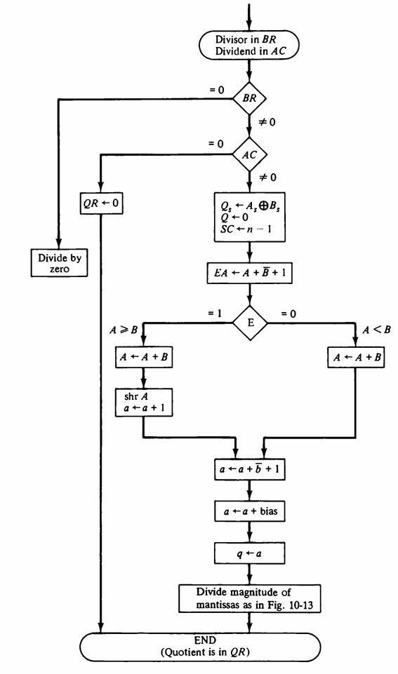
Extend the flowchart of Fig. 10-17 to provide a normalized floating-point remainder in the AC. The mantissa should be a fraction.Fig. 10-17 Divide by zero QR-0 A > B A + A + B shr A a+a+1 Divisor in BR Dividend in AC = 0 = 0 BR AC = 1 Qs + A, B, Q+0 SC-n-1 #0 EA + A + B + 1 E #0 a+a+b+1 a +a+
Show that there can be no mantissa overflow after a multiplication operation.
Show that the division of two normalized floating-point numbers with fractional mantissas will always result in a normalized quotient provided a dividend alignment is carried out prior to the division operation.
If we assume integer representation for the mantissa of floating-point numbers, we encounter certain scaling problems during multiplication and division. Let the number of bits in the magnitude part of the mantissa be (n - 1). For integer representation: a. Show that if a single-precision product
Show the hardware to be used for the addition and subtraction of two decimal numbers in signed-magnitude representation. Indicate how an overflow is detected.
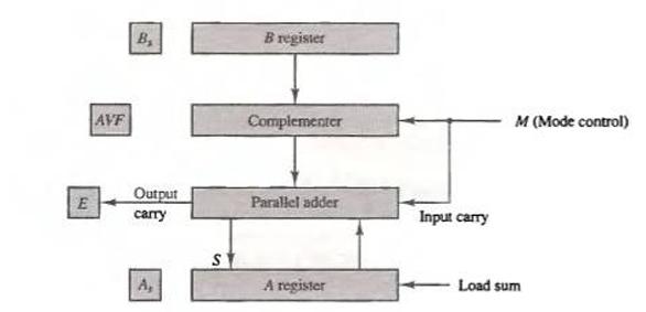
Show that the lower 4-bit binary adder in Fig. 10-1 can be replaced by one full-adder and two half-adders. Fig. 10-1 E AVF B₂ Output carry A, S Bregister Complementer Parallel adder A register Input carry M (Mode control) Load sum
Show that 673 - 356 can be computed by adding 673 to the 10's complement of 356 and discarding the end carry. Draw the block diagram of a three-stage decimal arithmetic unit and show how this operation is implemented. List all input bits and output bits of the unit.
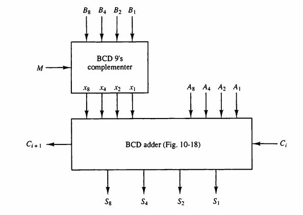
Using combinational circuit design techniques, derive the Boolean functions for the BCD 9's complementer of Fig. 10-19. Draw the logic diagram.Fig. 10-19 M Ci+1 Bg B4 B₂ B₁ BCD 9's complementer X8 X4 X2 X1 S8 III S4 BCD adder (Fig. 10-18) Ag A4 A₂ A₁ S₂ S₁ C₁
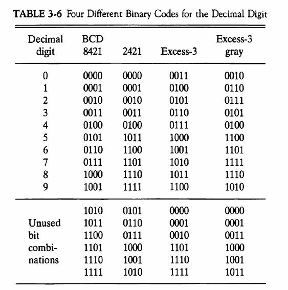
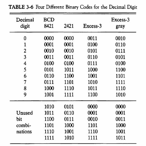
It is necessary to design an adder for two decimal digits represented in the excess-3 code (Table 3-6). Show that the correction after adding two digits with a 4-bit binary adder is as follows: a. The output carry is equal to the uncorrected carry. b. If output carry = 1, add 0011. c. If output
Derive the circuit for a 9's complementer when decimal digits are represented in the excess-3 code (Table 3-6). A mode control input determines whether the digit is complemented or not. What is the advantage of using this code over BCD?Table 3-6 TABLE 3-6 Four Different Binary Codes for the Decimal
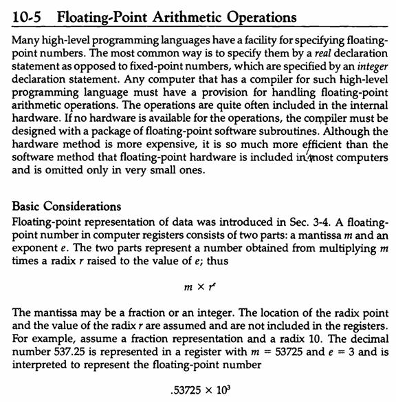
Change the floating-point arithmetic algorithms in Sec. 10-5 from binary to decimal data. In a table, list how each microoperation symbol should be interpreted. 10-5 Floating-Point Arithmetic Operations Many high-level programming languages have a facility for specifying floating- point numbers.
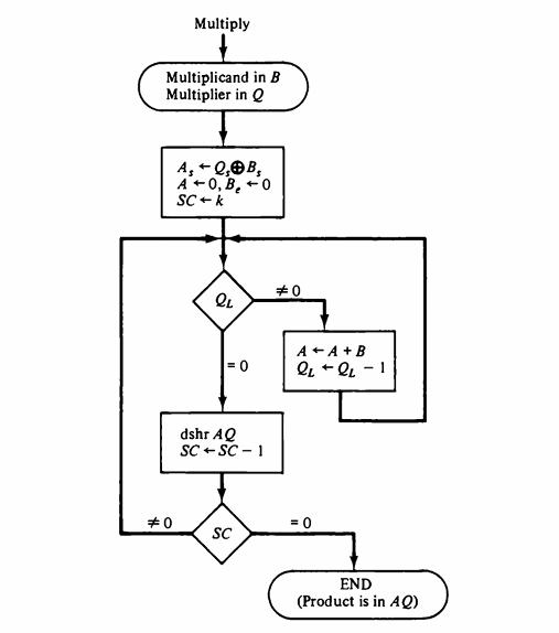
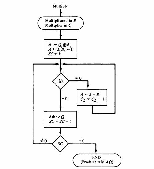
Show the content of registers A, B, Q, and SC during the decimal multiplication (Fig. 10-22) of (a) 470 x 152 and(b) 999 199. Assume three-digit registers and take the second number as the multiplier.Fig. 10-22 Multiply Multiplicand in B Multiplier in Q #0 + A, Q, B, A-0, B₂0 SC + k a QL =
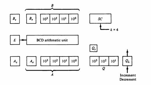
Show that subregister A, in Fig. 10-21 is zero at the termination of (a) The decimal multiplication as specified in Fig. 10-22, and (b) The decimal division as specified in Fig. 10-23.Fig. 10-21Fig. 10-22 Fig. 10-23 B E A₂ Be 103 102 101 10⁰ Ae BCD arithmetic unit 103 102 10¹ 10⁰ . SC k =
Show the content of registers A, E, Q, and SC during the decimal division (Fig. 10-23) of 1680/32. Assume two-digit registers.Fig. 10-23 #0 A
Show the hardware to be used for the addition and subtraction of two decimal numbers with negative numbers in signed-10's complement representation. Indicate how an overflow is detected. Derive the flowchart algorithm and try a few numbers to convince yourself that the algorithm produces correct
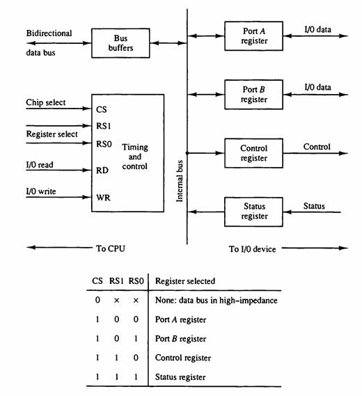
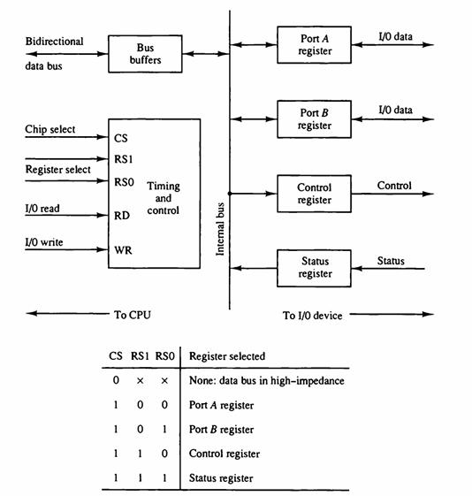
The addresses assigned to the four registers of the I/O interface of Fig. 11-2 are equal to the binary equivalent of 12, 13, 14, and 15. Show the external circuit that must be connected between an 8-bit I/O address from the CPU and the CS, RS1, and RS0 inputs of the interface.Fig. 11-2
Six interface units of the type shown in Fig. 11-2 are connected to a CPU that uses an I/O address of eight bits. Each one of the six chip select (CS) inputs is connected to a different address line. Thus the high-order address line is connected to the CS input of the first interface unit and the
List four peripheral devices that produce an acceptable output for a person to understand.
Write your full name in ASCII using eight bits per character with the leftmost bit always 0. Include a space between names and a period after a middle initial.
What is the difference between isolated I/O and memory-mapped I/O? What are the advantages and disadvantages of each?
Indicate whether the following constitute a control, status, or data transfer commands. a. Skip next instruction if flag is set. b. Seek a given record on a magnetic disk. c. Check if I/O device is ready. d. Move printer paper to beginning of next page. e. Read interface status register.
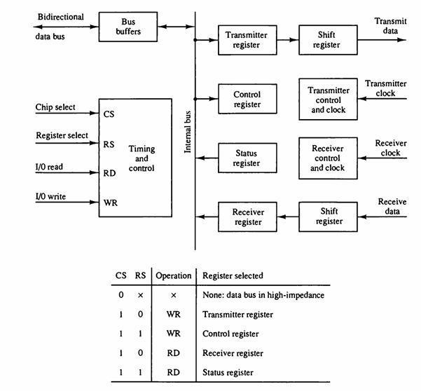
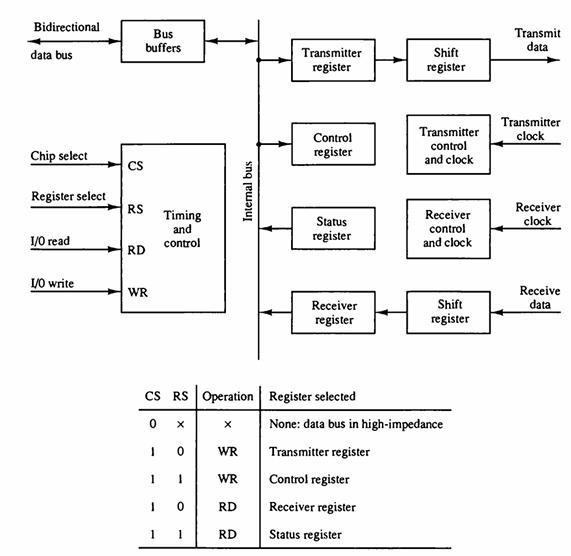
The asynchronous communication interface shown in Fig. 11-8 is connected between a CPU and a printer. Draw a flowchart that describes the sequence of operations in the transmitter portion of the interface when the CPU sends characters to be printed.Fig. 11-8 Bidirectional data bus Chip
A commercial interface unit uses different names for the handshake lines associated with the transfer of data from the I/O device into the interface unit. The interface input handshake line is labeled STB (strobe), and the interface output handshake line is labeled IBF (input buffer full). A
A CPU with a 20-MHz clock is connected to a memory unit whose access time is 40 ns. Formulate a read and write timing diagrams using a READ strobe and a WRITE strobe. Include the address in the timing diagram.
How many bits are there in the transmitter shift register of Fig. 11-8 when the interface is attached to a terminal that needs one stop bit? List the bits in the shift register when the letter W is transmitted using ASCII with even parity.Fig. 11-8 Bidirectional data bus Chip select Register
Give at least six status conditions for the setting of individual bits in the status register of an asynchronous communication interface.
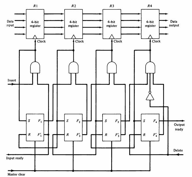
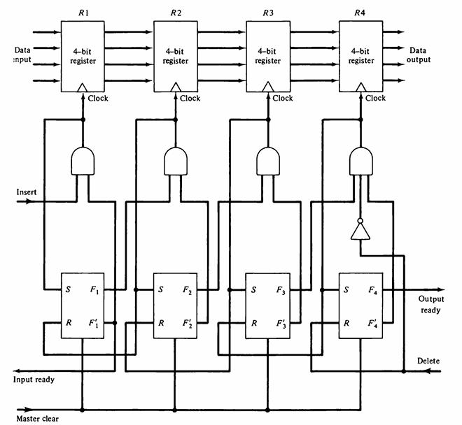
The bits in the control register of the FIFO shown in Fig. 11-9 are REF = 0011. Give the sequence of internal operations when an item is deleted from the FIFO and then a new item is inserted.Fig. 11-9 Data input Insert Input ready Master clear R1 4-bit register K Clock S
How many characters per second can be transmitted over a 1200-baud line in each of the following modes? (Assume a character code of eight bits.) a. Synchronous serial transmission. b. Asynchronous serial transmission with two stop bits.c. Asynchronous serial transmission with one stop bit.
What are the values of input ready and output ready and control bits F1 through F4 in Fig. 11-9 when: a. The buffer is empty? b. The buffer is full? c. The buffer contains two data items?Fig. 11-9 Data input Insert Input ready Master
Information is inserted into a FIFO buffer at a rate of m bytes per second. The information is deleted at a rate of n byte per second. The maximum capacity of the buffer is k bytes. a. How long does it take for an empty buffer to fill up when m > n? b. How long does it take for a full buffer to
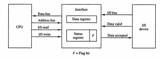
Show a block diagram similar to Fig. 11-10 for the data transfer from a CPU to an interface and then to an I/O device. Determine a procedure for setting and clearing the flag bit.Fig. 11-10 CPU Data bus Address bus 1/0 read 1/0 write Interface Data register Status register F = Flag bit F 1/0
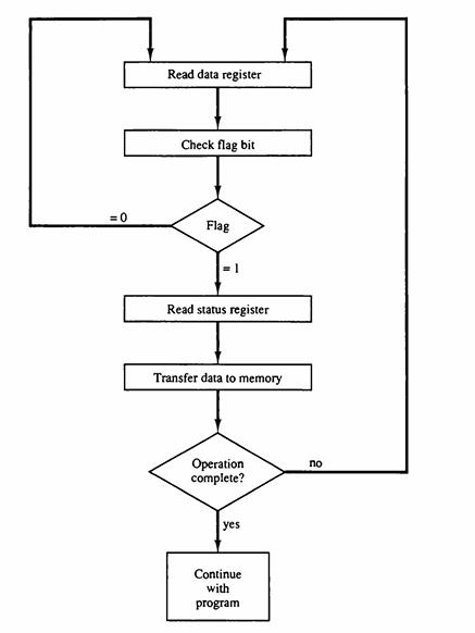
Using the configuration established in Prob. 11-16, obtain a flowchart (similar to Fig. 11-11) for the CPU program to output data.Prob. 11-16Show a block diagram similar to Fig. 11-10 for the data transfer from a CPU to an interface and then to an I/O device. Determine a procedure for setting and
What is the basic advantage of using interrupt-initiated data transfer over transfer under program control without an interrupt?
What happens in the daisy-chain priority interrupt shown in Fig. 11-12 when device 1 requests an interrupt after device 2 has sent an interrupt request to the CPU but before the CPU responds with the interrupt acknowledge?Fig. 11-12 VAD 1 Device I PI PO PI Processor data bus VAD 2 Device
In most computers an interrupt is recognized only after the execution of the instruction. Consider the possibility of acknowledging the interrupt at any time during the execution of the instruction. Discuss the difficulty that may arise.
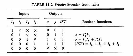
Using combinational circuit design techniques, derive the Boolean expressions listed in Table 11-2 for the priority encoder. Draw the logic diagram of the circuit.Table 11-2 Inputs 10 11 12 13 1 oooo. 0 0 0 0 0001X TABLE 11-2 Priority Encoder Truth Table Outputs X X100 0 0 1 1 000 X X X XXX-O Y
Consider a computer without priority interrupt hardware. Any one of many sources can interrupt the computer, and any interrupt request results in storing the return address and branching to a common interrupt routine. Explain how a priority can be established in the interrupt service program.
Design a parallel priority interrupt hardware for a system with eight interrupt sources.
Obtain the truth table of an 8 x 3 priority encoder. Assume that the three outputs xyz from the priority encoder are used to provide a vector address of the form 101xyz00. List the eight vector addresses starting from the one with the highest priority.
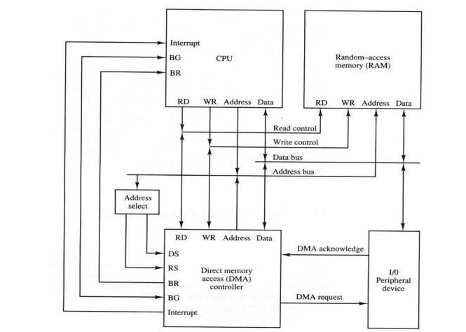
It is necessary to transfer 256 words from a magnetic disk to a memory section starting from address 1230. The transfer is by means of DMA as shown in Fig. 11-18. a. Give the initial values that the CPU must transfer to the DMA controller. b. Give the step-by-step account of the actions taken
What programming steps are required to check when a source interrupts the computer while it is still being serviced by a previous interrupt request from the same source?
Why are the read and write control lines in a DMA controller bidirectional? Under what condition and for what purpose are they used as inputs? Under what condition and for what purpose are they used as outputs?
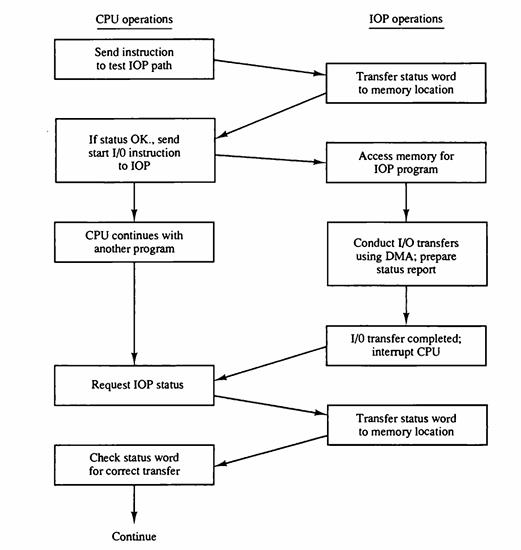
Draw a flowchart similar to the one in Fig. 11-20 that describes the CPU-VO channel communication in the IBM 370.Fig. 11-20 CPU operations Send instruction to test IOP path If status OK., send start 1/0 instruction to IOP CPU continues with another program Request IOP status Check status word for
ADMA controller transfers 16-bit words to memory using cycle stealing. The words are assembled from a device that transmits characters at a rate of 2400 characters per second. The CPU is fetching and executing instructions at an average rate of 1 million instructions per second. By how much will
Why does DMA have priority transfer? over the CPU when both request a memory
The address of a terminal connected to a data communication processor consists of two letters of the alphabet or a letter followed by one of the 10 numerals. How many different addresses can be formulated.
List a possible line procedure and the character sequence for the communication between a data communication processor and a remote terminal. The processor inquires if the terminal is operative. The terminal responds with yes or no. If the response is yes, the processor sends a block of text.
A data communication link employs the character-controlled protocol with data transparency using the DLE character. The text message that the transmitter sends between STX and ETX is as follows: DLE STX DLE DLE ETX DLE DLE ETX DLE ETX What is
Showing 200 - 300
of 330
1
2
3
4
Step by Step Answers


![Delayed Load Consider now the operation of the following four instructions: 1. LOAD: R1-M[address 1]](https://dsd5zvtm8ll6.cloudfront.net/images/question_images/1698/0/6/5/61565366ccfdb6aeimage_%282%29.png)


![Delayed Load Consider now the operation of the following four instructions: 1. LOAD: R1-M[address 1]](https://dsd5zvtm8ll6.cloudfront.net/images/question_images/1698/0/6/5/69165366d1b2fb47image_%282%29.png)


![Delayed Load Consider now the operation of the following four instructions: 1. LOAD: R1M[address 1]](https://dsd5zvtm8ll6.cloudfront.net/images/question_images/1698/0/6/5/74665366d529e0eaimage_%282%29.png)
![Delayed Load Consider now the operation of the following four instructions: 1. LOAD: R1M[address 1]](https://dsd5zvtm8ll6.cloudfront.net/images/question_images/1698/0/6/5/80565366d8d74a68image_%282%29.png)
![Load ADD INC STORE R1-M[312] R2 R2 + M[313] R3 R3 +1 M[314] R3](https://dsd5zvtm8ll6.cloudfront.net/images/question_images/1698/0/4/7/75265362708a47eb1698047749364.jpg)