New Semester
Started
Get
50% OFF
Study Help!
--h --m --s
Claim Now
Question Answers
Textbooks
Find textbooks, questions and answers
Oops, something went wrong!
Change your search query and then try again
S
Books
FREE
Study Help
Expert Questions
Accounting
General Management
Mathematics
Finance
Organizational Behaviour
Law
Physics
Operating System
Management Leadership
Sociology
Programming
Marketing
Database
Computer Network
Economics
Textbooks Solutions
Accounting
Managerial Accounting
Management Leadership
Cost Accounting
Statistics
Business Law
Corporate Finance
Finance
Economics
Auditing
Tutors
Online Tutors
Find a Tutor
Hire a Tutor
Become a Tutor
AI Tutor
AI Study Planner
NEW
Sell Books
Search
Search
Sign In
Register
study help
sciences
college physics reasoning
College Physics Reasoning and Relationships 2nd edition Nicholas Giordano - Solutions
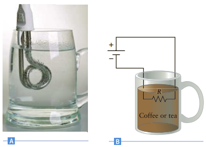
Figure P19.112A shows an immersion heater. It is just a small coil with a resistance R that is used to heat a beverage such as a cup of tea. The heater is connected to a source of emf causing heat to be dissipated in the resistor that heats the tea (Fig. P19.112B). If a cup of tea is initially at
. For muscle rehabilitation, patients can be fitted with a small electrical device designed to help strengthen muscle tissue. With this device, a small electrical current is passed through the muscle tissue, stimulating muscle contraction in that region. With involuntary muscle stimulation
Electrical wire comes in different sizes (different diameters), which are referred to according to their “gauge” number. For example, a 16-gauge wire has a diameter of approximately 1.29 mm and is often used for extension cords. Suppose a 9.0-m extension cord composed of 16-gauge copper
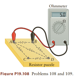
Consider again the configuration of resistors shown in Figure P19.108. As in Problem 108, each connection can have a resistor that is disconnected or whose value is 5.0 Ω or 10.0 Ω. This time, you measure a resistance of 6.25 Ω between points A and B, between A and C, between C and D, and
Consider the configuration of resistors shown in Figure P19.108. Each connection can have a resistor that is disconnected or whose value is 5.0Ω or 10.0Ω. To determine the value of each resistor or disconnection point, you measure the following with an ohmmeter: RAB = 5.0 Ω, RAC =
Hydroelectric power. Niagara Falls has one of the largest hydroelectric power-generating facilities in the world, providing one fourth of New York State’s and all of Ontario’s electrical energy. The Canadian portion of the falls is called Horseshoe Falls based on its shape (Fig. P19.107).
Most recreational vehicles and boats have the capability of operating electrical appliances using a 12-V battery, which either requires the use of special appliances designed to run on 12-V DC or the use of an inverter that converts direct current to alternating current as used in our homes.
As discussed in Chapter 18, lightning is one of nature’s most impressive displays. For a typical storm, a lightning bolt is generated when the average electric fi eld is about 10% of the breakdown fi eld for air. Consider a case in which the bottom of the storm cloud is 500 m above the Earth’s
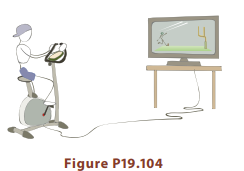
With the level of childhood obesity reaching epidemic proportions in the United States, one inventor decided to create a device to make children exercise to generate the electrical energy required for them to watch television. Attaching a small electric generator to a stationary exercise bike, the
A 100-W lightbulb and a 60-W lightbulb are connected to a 120-V source. Determine the voltage across each lightbulb if they are connected(a) in series(b) in parallel.
A 70Ω electrical appliance and a 200 Ω electrical appliance are plugged into the outlets of a house. By what factor will the power used change if an additional 400 Ω electrical device is plugged in?
Three resistors R1, R2, and R3 are initially connected in parallel to a 12-V source. The total current supplied to the three resistors is 500 μA. Assume R1 has a resistance of 40,000Ω and R2 has a current running through it of 100 μA. If the 12-V supply is kept in place but R3 is moved so that
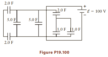
Seven capacitors are connected to a 100-V battery as shown in Figure P19.100.(a) What is the total equivalent capacitance of the circuit?(b) Determine the total charge stored in the capacitors when they are fully charged.(c) Determine the total energy stored in the capacitors when they are fully
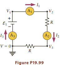
Several ammeters are placed in the circuit in Figure P19.99.(a) Arrange the values of the potentials (V1, V2, . . .) from highest to lowest (b) Arrange the values of the currents measured by the ammeters (I1, I2, . . .) from highest to lowest. V2 E1 A2 I3T(A3 V3 V = 0- Figure P19.99 R.
A marine battery has an emf of approximately 12.5 V and an internal resistance of 0.075Ω. The starter motor for the outboard engine requires 40 A while cranking the engine.(a) Determine the potential difference across the starter motor when it is cranking.(b) What is the resistance of the starter
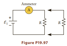
A battery is connected to a single resistor (Fig. P19.97), and the current is measured with an ammeter. A second resistor having the same resistance is placed in parallel with the fi rst resistor. Does the current through the ammeter increase or decrease? Explain your answer. Ammeter A R-
Design a parallel-plate capacitor that is able to store the same amount of energy as in the AA battery mentioned in Example 19.2 (7000 J). Give the area of the plates, the plate separation, and the composition of the dielectric and determine the voltage across the capacitor.
Consider a bird as it flies to and lands on a power line with a potential V 880 V relative to ground potential. Just before the bird lands on the power line, the bird’s potential is zero; after it lands, its potential is 880 V. Long after it lands, the current through the bird is zero, but there
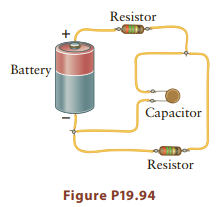
Figure P19.94 shows a realistic sketch of a circuit. Draw the corresponding circuit diagram. Resistor Battery Capacitor Resistor Figure P19.94
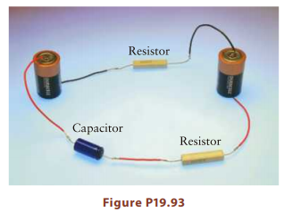
The photo in Figure P19.93 shows an electric circuit containing resistors, batteries, and a capacitor. Draw a circuit diagram that corresponds to this circuit. Resistor Capacitor Resistor Figure P19.93 PAMA
Suppose that electrical energy costs about $0.093/(kW hour) (that is what you pay your local electric company). In a recent month, the author’s electric bill was $150.(a) If the electric potential provided by the electric company was 120 V, what was the average current in all circuits in the
Consider a resistor that dissipates 0.50 W when attached to a battery with an emf of 120 V. If this resistor is attached to a battery with a emf of 9.0 V, how many electrons pass through the resistor each second?
Platinum wires are often used as thermometers due to the change in resistivity of platinum with temperature. The temperature coefficient of resistivity for platinum is α = 3.9 x 10⁻³ K-1. Suppose a platinum resistance thermometer has a resistance of 100 Ω at room temperature (293 K). If the
The fi lament of an incandescent lightbulb is a thin tungsten wire. Suppose a lightbulb has a resistance of 50 Ω at room temperature. During normal operation, the filament reaches a temperature of about 3000 K.(a) What is its resistance at that temperature? The temperature coefficient of
The temperature coefficient of resistivity for copper is a 3.9 x 10⁻³ K-1. If a copper wire has a resistance of 350Ω at 20 K, what is its resistance at 420 K?
A defibrillator is used by emergency medical staff to shock the heart of an accident victim by applying a 10,000-V potential difference across the victim’s chest.(a) If the defibrillator has an internal resistance of 10 Ω and the victim’s heart has a resistance of 300 Ω, what is the current
Consider a single ion channel (Problem 85) with R = 109Ω. During an action potential, this channel is open for approximately 1.0 ms for the flow of Na+ ions with a potential difference across the cell membrane of about 70 mV. How many Na ions travel through the channel?
Cell membranes contain openings called ion channels that allow ions to move from the inside of the cell to the outside. Consider a typical ion channel with a diameter of 1.0 nm and a length of 10 nm. If this channel has a resistance of 1.0 x 10⁹ Ω, what is the resistivity of the solution in the
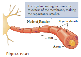
Consider the nerve fiber discussed in Example 19.10. Assume the fi ber is coated with a layer of myelin that is 100 nm thick. If the dielectric constant of myelin is the same as for a lipid layer, what is the time constant of this fiber? Ignore the gaps in the myelin sheath in Figure 19.41. These
It is possible to devise clever circuit arrangements that behave as ideal meters. The circuit in Figure P19.83 is able to measure the voltage across resistor R4 without affecting the original circuit. The resistor R1 is an adjustable resistor whose value can be varied (e.g., by turning a knob).
Suppose an ammeter and voltmeter are used to determine a resistor’s resistance. If the ammeter is connected in series with the resistor and the voltmeter is connected across the resistor only, show that the correct resistance of the resistor is given by R V/[I - (V/RV)], where V is the voltage
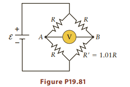
Consider the circuit in Figure P19.81. Find the potential difference between points A and B. Express your answer in terms of ε and R. Assume the voltmeter is ideal `R' = 1.01R Figure P19.81
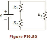
For the circuit in Figure P19.80, draw the proper placement of an ammeter or voltmeter to measure(a) the current through and voltage across R1,(b) the current through and voltage across (R1 + R2),(c) the current through and voltage across R3, and(d) the total current through the battery.
Suppose a voltmeter has an internal resistance of 50 kV. Determine the current through the meter when it is properly connected across a 50-V resistor that is connected to a 10-V source. R1 R3 R2 Figure P19.80
Suppose an ammeter has an internal resistance of 1.0 mV. Find the current in the ammeter when it is properly connected to a 2.0000-V resistor and a 12.000-V source. Express your answer to four significant figures.
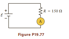
Although an ideal ammeter has an internal resistance of zero, this theoretical ideal is usually not met in practice. The ammeter in Figure P19.77 has an internal resistance of 0.010 V and is used to measure the current in a circuit containing a resistor with R = 150Ω as shown. How much does
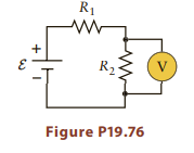
Although an ideal voltmeter has an infinite internal resistance, this theoretical ideal is usually not met in practice. The voltmeter in Figure P19.76 has an internal resistance of 109 Ω and is used to measure the voltage across a resistor with R2 = 150 kΩ as shown. How much does this nonideal
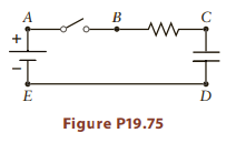
Consider the circuit in Figure P19.75. Match each hypothetical change in the circuit in the left column with the effect that change would have on the right(a) Attach a resistor between points A and E.(b) Attach a resistor between points B and C(c) Attach a resistor between points B and D.(i)
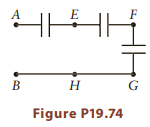
Consider the circuit in Figure P19.74. Match each hypothetical change in the circuit in the left column with the effect that change would have on the right.(a) Attach a capacitor between points E and F.(b) Attach a capacitor between F and G.(c) Replace the wire connecting points G and H with a
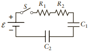
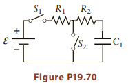
Consider the circuit in Figure P19.72 and assume the switch has been closed for a very long time. What is the current through the circuit? What are the charges on the two capacitors?Figure P19.72 In the circuits in Figures P19.67, P19.70, and P19.72, assume the resistance values are R1 =
The capacitors in Figure P19.72 are initially uncharged when the switch is closed. Make a sketch of how the current through the circuit varies with time after the switch is closed. What is the time constant for this circuit? In the circuits in Figures P19.67, P19.70, and P19.72, assume the
Consider again the circuit in Figure P19.70. After switch S1 is closed for a very long time, switch S1 is opened and switch S2 is simultaneously closed.(a) What is the current through switch S2 the instant after it is closed?(b) Make a sketch of how this current varies with time.(c) What is the
The capacitor in Figure P19.70 is initially uncharged, and both switches are open. What is the current through the battery the instant after switch S1 is closed? In the circuits in Figures P19.67, P19.70, and P19.72, assume the resistance values are R1 = 1500Ω and R2 = 2400 Ω, and with
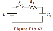
What is the time constant for the circuit in Figure P19.67? Sketch how the current through the circuit and the voltage across the capacitor vary with time after the switch is closed. In the circuits in Figures P19.67, P19.70, and P19.72, assume the resistance values are R1 = 1500Ω and R2 =
If the switch in Figure P19.67 is closed for a very long time, what is the charge on the capacitor? In the circuits in Figures P19.67, P19.70, and P19.72, assume the resistance values are R1 = 1500Ω and R2 = 2400 Ω, and with capacitances C1 = 45 μF and C2 = 25 μF. The emf is ε = 5.5 V.
What is the current in the circuit in Figure P19.67 the moment after the switch is closed? Assume the capacitor is initially uncharged.In the circuits in Figures P19.67, P19.70, and P19.72, assume the resistance values are R1 = 1500Ω and R2 = 2400 Ω, and with capacitances C1 = 45 μF and C2 =
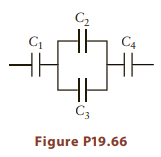
Figure P19.66. If C1 = 2.5 μF, C2 = 4.5 μF, C3 = 3.3 μF, and C4 = 1.5 μF, what is their equivalent capacitance? C2 C4 C3 Figure P19.66
Seven capacitors, all with the same capacitance C, are connected in series. What is the value of the equivalent capacitor?
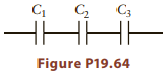
Consider the three capacitors in Figure P19.64. If C1 = 2.5 ?F, C2 = 3.5 ?F, and C3 = 1.5 ?F, what is the equivalent capacitance? ? C3 HHHE Figure P19.64
Five capacitors, all with the same capacitance C, are connected in parallel. What is the value of the equivalent capacitor?
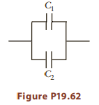
The capacitors in Figure P19.62 have capacitances C1 = 7.5 μF and C2 = 3.5 μF. What is the equivalent capacitance of this arrangement? Figure P19.62
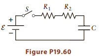
For the circuit in Problem 60, what is the current through the circuit(a) just after the switch is closed(b) after the switch has been closed for a very long time? The circuit in Problem 60 ?? S R R2 + C Figure P19.60
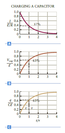
Consider the RC circuit in Figure P19.60, with R1 = 1000 V, R2 = 3000 V, and C = 1.0 mF. When the switch is closed, the current will vary with time as sketched in Figure 19.30A. What is the time constant for the circuit in Figure P19.60? Figure P19.30 ? Figure P19.60 ? CHARGING A CAPACITOR 1.0
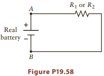
A real battery has some internal resistance Rint in series with an ideal battery with an emf of V0. In an attempt to determine Rint and V0 of such a battery, the voltage across the battery terminals is measured with the battery disconnected from any circuit elements and is found to be 9.50 V. A
Analyzing a real battery. The battery in Figure P19.58 is a real battery. That is, it has some internal resistance Rint in series with an ideal battery with an emf of V0. In an attempt to determine Rint and V0, a resistor R1 = 750Ω is first placed across points A and B, and the voltage across the
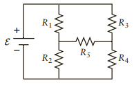
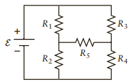
Consider the circuit in Figure P19.55, with resistors R1 = 750Ω, R2 = 250Ω, and R3 = 420 Ω. For what value of resistor R4 is the current through resistor R5 zero? R3 R1 R5 R4 R2
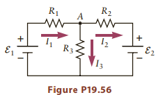
Use Kirchhoff’s rules to analyze the circuit in Figure P19.56.(a) Let I1 be the branch current though R1, I2 be the branch current through R2, and I3 be the branch current through R3. Write Kirchhoff’s loop rule relation for a loop that travels through battery 1, resistor 1, and resistor 3.(b)
Consider the circuit in Figure P19.55, with resistors R1 = 750Ω, R2 = 250 Ω, R3 = 420 Ω, R4 = 170 Ω, and R5 = 750 Ω, and battery with emf ε = 9.0 V. Does current flow from left to right or from right to left through resistor R5? Explain how you know. R3 R1 R5 R4 R2
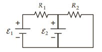
Consider again the circuit in Figure P19.53. Write the Kirchhoff’s loop rule relation for a loop that passes through battery 1, resistor 1, and resistor 2. Show that the resulting equation can be derived by combining the two loop equations from Problem 53.Figure 919.53R1 = 2400 V, R2 = 1400 V, R3
Use Kirchhoff’s rules to analyze the circuit in Figure P19.53.(a) Let I1 be the branch current through R1 and I2 be the branch current through R2. Write Kirchhoff’s loop rule relation for a loop that travels through battery 1, resistor 1, and battery 2.(b) Write Kirchhoff’s loop rule relation
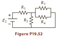
Use the approach from Problems 50 and 51 to analyze the circuit in Figure P19.52. What is the current through the battery and resistor R1? Hint: First redraw the circuit so that the parallel and series resistor combinations are more obvious. R3 R1 R2 3 E2 R4 Figure P19.52
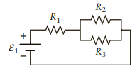
Use your results from Problem 50 to fi nd the current through R2 in Figure P19.48. Hint: First fi nd the voltage across the parallel combination of resistors.Figure P19.48R1 = 2400 V, R2 = 1400 V, R3 = 4500 Ω, and R4 = 6000 Ω, and the battery emfs are ε1 = 5 1.5 V and ε2 = 5 3.0 V, unless
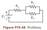
Analyze the circuit in Figure P19.48.(a) Express the resistors in parallel as a single equivalent resistor. What is the value of this resistor?(b) Combine this equivalent resistor with R1 to get the total equivalent resistance of the circuit. What is the value of this resistor?(c) The circuit is
Consider the circuit in Figure P19.48 and assume all the resistors are identical. Only one of the following statements is true. Which one?(a) The power dissipated is the same in all three resistors.(b) The power dissipated in R1 is greater than the power dissipated in R2. (c) The power
Consider the circuit in Figure P19.48. The resistors are identical with R1 = R2 = R3 = 2000 Ω, and the battery voltage is ε1 = 9.0 V. What is the current through resistor R1? R2 R1 R3 Figure P19.48 Problems
You are given four resistors, each with resistance R. Devise a way to connect these resistors so that the total equivalent resistance is R. No cheating; you must use all the resistors so that there is current through each one if a battery is connected.
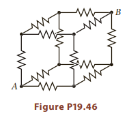
Consider the cube of resistors in Figure P19.46. If all the resistors have the same value, what is the equivalent resistance between points A and B? Start by considering a Kirchhoff?s rule analysis and sketch the various branch currents. Can you fi nd some relation(s) between these currents?? B
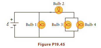
The lightbulbs in Figure P19.45 are all identical. Which bulb will be brightest? Which one will be dimmest? Bulb 2 Bulb 1 Bulb 3 Bulb 4 Figure P19.45
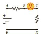
Consider the circuit in Figure P19.44. Match each hypothetical change in the circuit in the left column with the effect that change would have on the right. (a) Attach a resistor between A and B. (b) Attach a resistor between points B and C. (c) Attach a resistor between A
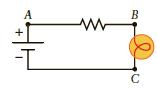
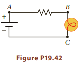
How could you connect another resistor to the circuit in Figure P19.42 so as to reduce the brightness of the bulb? That is, would you connect the new resistor to points A and B, A and C, or B and C? A B C
Figure P19.42 shows a circuit containing a battery in series with a resistor and a lightbulb. The brightness of the lightbulb depends on the current through the bulb: increasing the current increases the brightness, while decreasing the current reduces the brightness. How could you connect another
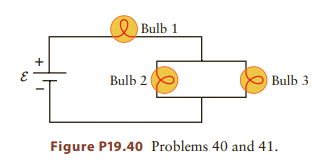
If bulb 2 in Figure P19.40 burns out and then acts as an open circuit (i.e., an infinite resistance), what happens to the brightness of bulbs 1 and 3? Assume the resistances of the other bulbs do not change.(i) The brightness of both bulbs stays the same.(ii) Bulbs 1 and 3 both get brighter.(iii)
The circuit in Figure P19.40 shows three identical lightbulbs attached to an ideal battery with ε = 18 V. If the resistance of each bulb is 200 Ω, fi nd the current through bulb 1 and the current through bulb 2. O Bulb 1 Bulb 2 Bulb 3 Figure P19.40 Problems 40 and 41.
Two appliances are connected in parallel to a 120-V battery and draw currents I1 5 2.0 A and I2 5 3.5 A. If these appliances are instead connected in series to the same battery, what is the total current in the circuit?
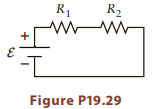
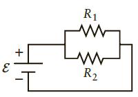
If the current in the circuit in Figure P19.29 is 0.15 A and the resistances are R1 = 1500 Ω and R1 = 2500 Ω, what is the emf of the battery? R1 R2 Figure P19.29
An electric heater consumes electrical energy at a rate of P 5 250 W when connected to a battery with an emf of 120 V.(a) What is the current in the heater?(b) If you wish to increase the power consumption to 500 W, by what factor should the heater resistance be changed?(c) What is the maximum
A typical lightbulb in your residence is rated 100 W, which means that the bulb dissipates 100 W when connected to a DC voltage of 110 V.(a) What is the current?(b) If the voltage is reduced to 55 V, what is the dissipated power? Assume the resistance does not change when the voltage is reduced.
Consider the resistors in series in Figure P19.29. If R1 = 2500 V and R2 = 3500 V, what is the ratio of the powers dissipated in the two resistors? R1 R2 Figure P19.29
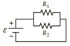
Consider the resistors in parallel in Figure P19.26. If R1 = 2500 V and R2 = 6500 V, what is the ratio of the powers dissipated in the two resistors? 3 -I R www www R
Consider the circuit in Figure P19.29 with R1 = 1500 Ω and R2 = 3500 Ω. If ε = 12 V, what is the power dissipated in R2? R1 R2 Figure P19.29
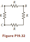
Consider the circuit in Figure P19.32 with four identical resistors R connected to make a square.(a) What is the resistance between points A and B?(b) Between points B and C? в A Ce Figure P19.32
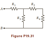
Consider the circuit in Figure P19.31 with resistors R1 = 550 Ω, R2 = 5 400 Ω, R3 = 220 Ω, and R4 = 170 Ω. What is the equivalent resistance between points A and B? R2 R1 R33 R4 B- Figure P19.31
Seven resistors, all with resistance R, are connected in series. What is the equivalent resistance of this combination?
Two resistors with R1 = 1500 V and R2 = 3500 V are connected in series as shown in Figure P19.29.(a) If the battery emf is ε = 12 V, what is the current through each of the resistors?(b) What is the equivalent resistance of the two resistors? R1 R2 Figure P19.29
Five resistors, all with resistance R, are connected in parallel. What is the equivalent resistance of this combination?
What is the equivalent resistance of the two resistors in Problem 26? Resistor Problem 26 R1 R2
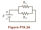
Two resistors with R1= 1500 Ω and R2 = 3500 Ω are connected in parallel as shown in Figure P19.26. If the battery emf is ε = 12 V, what is the current through each of the resistors? R1 R2 Figure P19.26 3.
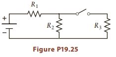
The three resistors in Figure P19.25 all have the same resistance. When the switch is closed,(a) by what factor does the current in resistor 1 change?(b) By what factor does the potential difference across resistor 2 change?(c) By what factor does the current in resistor 2 change? R1 R2 R3
A resistor with R = 50 Ω is connected to a battery with emf ε = 3.0 V.(a) What is the current through the battery?(b) What is the current through the resistor?(c) What is the power dissipated in the resistor?(d) How much energy is dissipated in the resistor in 3 minutes?
Consider the circuit in Figure P19.23 with resistors R1 = 2500Ω and R2 = 4500 Ω, and R3 = 1200 Ω, batteries with emfs ε1 = 6.5 V and ε2 = 1.3 V. What is the magnitude of the current in the circuit?
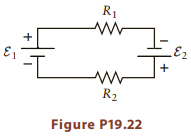
Consider the circuit in Figure P19.22 with resistors R1 = 3200Ω and R2 = 8100 Ω, and batteries with emfs ε1 = 7.5 V and ε2 = 2.3 V. What is the magnitude of the current in the circuit? R1 E2 R2 Figure P19.22
If a current of 0.10 A flows through a resistor and the potential drop across the resistor is 1.5 V, what is the resistance?
There is a potential difference of V 20 V across a resistor with R = 50Ω. What is the current through the resistor?
A copper wire is made with the same diameter and length as the capillary tube in Problem 18. What is the ratio of the resistance of the capillary tube to the resistance of the copper wire?
A glass capillary tube with a diameter of 0.50 mm and length 10 cm is filled with a salt solution with a resistivity of 0.10Ωm. What is the resistance?
If the current through a resistor is increased by a factor of 3, by what factor does the power change?
If the current through a resistor is increased by a factor of 3, by what factor does the voltage change?
It is possible to get copper wires with diameters as small as about 1 μm. If such a wire has a resistance of 5Ω how long is it?
An aluminum wire has a diameter of 0.50 mm and a length of 7.5 m. What is its resistance?
The electric eel (Electrophorus electricus) can generate a potential difference of 600 V between a region just behind its head and its tail. Suppose an unsuspecting fi sh swims into this area, resulting in a lethal current of 1.0 A passing through the length of its body. If the fi sh is
Showing 3200 - 3300
of 4913
First
26
27
28
29
30
31
32
33
34
35
36
37
38
39
40
Last
Step by Step Answers