New Semester
Started
Get
50% OFF
Study Help!
--h --m --s
Claim Now
Question Answers
Textbooks
Find textbooks, questions and answers
Oops, something went wrong!
Change your search query and then try again
S
Books
FREE
Study Help
Expert Questions
Accounting
General Management
Mathematics
Finance
Organizational Behaviour
Law
Physics
Operating System
Management Leadership
Sociology
Programming
Marketing
Database
Computer Network
Economics
Textbooks Solutions
Accounting
Managerial Accounting
Management Leadership
Cost Accounting
Statistics
Business Law
Corporate Finance
Finance
Economics
Auditing
Tutors
Online Tutors
Find a Tutor
Hire a Tutor
Become a Tutor
AI Tutor
AI Study Planner
NEW
Sell Books
Search
Search
Sign In
Register
study help
sciences
college physics reasoning
College Physics Reasoning and Relationships 2nd edition Nicholas Giordano - Solutions
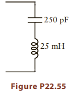
Estimate the impedance of the LC circuit in Figure P22.55 at the very high frequency of 30 MHz. Will this impedance be dominated by the capacitor or the inductor? Will this impedance increase or decrease if the frequency is increased? 250 pF 25 mH Figure P22.55
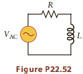
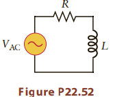
Consider the circuit in Figure P22.52. The voltage of the AC source is V = Vmax sin (2πft). If the frequency is extremely low (i.e., if f is very small), what is the amplitude of the current in the circuit? Express your answer in terms of Vmax, R, and L.
An LCR circuit contains a resistor with R = 4500Ω, a capacitor with C = 5500 mF, and an inductor with L = 2.2 mH, all connected in series. The AC source has a frequency of 75 kHz.(a) What is the impedance of the circuit?(b) What phase angle does the phasor describing the voltage across the
Consider the RL circuit in Figure P22.52 with R = 1500Ω, L = 2.5 mH, and an AC frequency of 70 kHz. What is the phase angle ϕ between the phasors that represent VAC and the current? VAC Figure P22.52
When an LC circuit is at resonance, is the impedance (a) zero,(b) 2πfL,(c) 1/(2πfC),(d) 1/√LC
An inductor with L = 35 mH is connected in parallel with a capacitor with C = 75 mF.(a) If they are connected to an AC voltage source with f = 2.5 kHz, where is the current larger, in the inductor or in the capacitor?(b) At what frequency is the current amplitude the same?
You are given a collection of inductors and capacitors and are asked to construct LC circuits for several different applications. The inductances range from L = 10 μH to 85 mH, and the capacitances are in the range of C = 200 pF to 1.5 mF. Is it possible to use these inductors and capacitors (one
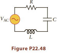
The LCR circuit in Figure P22.48 is driven by a voltage source with VAC = Vmax sin(2πft), where Vmax = 12 V, R = 150Ω, and C = 25 nF.(a) If the resonant frequency is fres = 95 MHz, what is L?(b) What is the amplitude (the peak value) of the current when f = fres? VAC Figure P22.48
An LC circuit with L = 55 mH is used in a radio to determine the frequency of a selected radio station. The station’s frequency is equal to the resonant frequency of the circuit.(a) The radio is initially set for a frequency f = 1.05 MHz. What is the value of C?(b) This capacitance is then
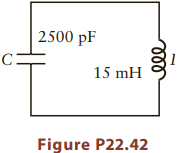
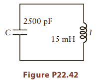
Consider again the LC circuit in Problem 42 and Figure P22.42. If the charge on the capacitor at a particular instant is 5.0 x 10⁻⁸ C, and the energy stored in the capacitor is equal to the energy stored in the inductor, what is the current at that moment? 2500 pF C: 15 mH Figure P22.42
An LC circuit has L = 0.50 mH and C = 1.2 mF. If the total energy stored in this circuit is 2.5 μJ (2.5 x10⁻⁶ J), what are(a) the maximum charge qmax on the capacitor and(b) the maximum current?(c) When the charge on the capacitor is qmax/2, what is the magnitude of the current?
An LC circuit has a resonant frequency f = 50 kHz, and L = 0.44 mH. What is the capacitance of the capacitor?
Consider the LC circuit in Problem 42 and Figure P22.42. At t = 0, the current is I = 45 mA and the charge q on the capacitor is zero.(a) What is the energy stored in the inductor at t = 0?(b) At some instant t1, the current will be zero. What is the charge on the capacitor at t1?(c) Find t1.
Consider an LC circuit with L = 15 mH and C = 2500 pF (Fig P22.42).(a) At what frequency is the reactance of the inductor equal to the reactance of the capacitor?(b) What is the resonant frequency of this circuit? |2500 pF 15 mH Figure P22.42
The resonant frequency of an LC circuit is f0.(a) If the inductance is increased by a factor of eight, what is the new resonant frequency?(b) How should the capacitance be changed to change the resonant frequency back to f0?
Consider an inductor with L = 50 mH and a resistor with R = 20 kΩ. At what frequency is the reactance of the inductor equal to the resistance of this resistor?
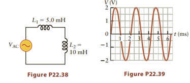
Figure P22.39 shows the voltage across an inductor with L = 20 mH.(a) At what time is the energy stored in the inductor a maximum? What is the energy at that moment?(b) At what time is the energy stored in the inductor a minimum? What is the energy at that moment?
The voltage source in Figure P22.38 has an amplitude of 5.0 V and a frequency of 75 Hz. What is the amplitude of the current through the inductors? V (V) L = 5.0 mH ll t (ms) VAC L2 = 10 mH -1 Figure P22.39 Figure P22.38
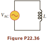
Draw a phasor diagram that shows the voltage across and current through the inductor in Problem 36. See Figure P22.36. AC Figure P22.36
Consider the circuit in Figure P22.36.(a) If the current through the inductor (L = 25 mH) at 400 Hz has an amplitude of 55 mA, what is the amplitude of the AC voltage?(b) What is the rms value of the AC voltage across the inductor? AC Figure P22.36
Find the reactance of an inductor with L = 15 mH at 22 kHz. If the frequency is increased to 66 kHz, by what factor does the reactance change?
An inductor has a reactance of 5500Ω at a frequency of 2500 Hz. What is the value of L?
You are given two inductors with inductances of 40 μH and 80 mH. If the frequency is 5000 Hz, which inductor has the larger reactance?
In an AC circuit, does the voltage across an inductor differ in phase from the current by a phase angle of (a) zero,(b) 30°,(c) 45°,(d) 90°,(e) 180°
The phase angle between the voltage and current in an AC circuit is 90°. Is the average power delivered to the circuit from the AC source positive, negative, or zero?
Two capacitors with C1 = 4.5 mF and C2 = 1.9 mF are connected in series. What is the reactance of the equivalent capacitance at 350 Hz?
Two capacitors with C1 = 450 pF and C2= 820 pF are connected in parallel. What is the reactance of the equivalent capacitance at 30 kHz?
Consider a circuit containing a resistor with R = 1200Ω and a capacitor with C = 6.5μF. At what frequency does the reactance of the capacitor equal the resistance of the resistor?
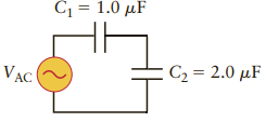
Two capacitors are connected to an AC source as shown in Figure P22.27; assume VAC = Vmax = sin(2μft), with Vmax = 18 V and a frequency f 2000 Hz. (a) What is the amplitude (peak value) of the current through the capacitors?(b) What is the rms current?Figure 22.17 Č1 = 1.0 µF C2 = 2.0 µF
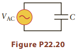
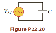
For the circuit in Figure P22.20, find(a) the average power,(b) the maximum instantaneous power,(c) the minimum instantaneous power delivered to the capacitor. Use f 400 Hz, Vmax = 25 V, and C = 1.5 μF. AC Figure P22.20
Consider the AC circuit in Figure P22.20 and assume VAC = Vmax sin(2πft) with Vmax = 12 V, f = 300 Hz, and C = 1.5μF. The charge on the capacitor will also vary sinusoidally. Find(a) the amplitude of the charge oscillation(b) the maximum energy stored in the capacitor.(c) At what time t is the
The AC voltage across a capacitor with C = 1.5μF has an amplitude of Vmax = 22 V, and the current through the capacitor has an amplitude of 2.5 mA. What is the frequency?
A capacitor has a reactance of 450Ω at 1200 Hz. What is its capacitance?
If the frequency is increased from 35 Hz to 140 Hz, does the reactance of a capacitor increase or decrease? By what factor does it change?
What is the reactance of a 1200-pF capacitor at 400 Hz?
An AC voltage source with a frequency of 120 Hz and an amplitude Vmax = 25 V is connected across a capacitor with C = 1.5μF (Fig. P22.20). Draw a phasor diagram showing the voltage across and the current through the capacitor. What is the length of the phasor that represents the current
You are given two capacitors with capacitances of 20 pF and 20 μF. If the frequency is 5000 Hz, which capacitor has the larger reactance?
In an AC circuit, does the voltage across a capacitor differ in phase from the current by a phase angle of (a) zero,(b) 30°,(c) 45°,(d) 90°,(e) 180°
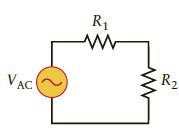
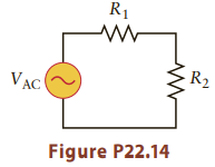
Consider the circuit in Figure P22.16 and suppose R1 = 20Ω and R2 = 40Ω. If the total average power dissipated in the two resistors is 55 W, what is the amplitude Vmax of the AC voltage?
Make a phasor diagram for the circuit in Figure P22.16 showing the voltage across each resistor and the current through each resistor. Do these phasors make the same angle with the horizontal axis? Express the length of the phasors in terms of the amplitude Vmax of the AC voltage source, and R1 and
Make a phasor diagram for the circuit considered in Problem 14, showing the voltage across each resistor and the current through the circuit. Do these three phasors all make the same angle with the horizontal axis? Explain why or why not. R1 R2 VAC
Consider the AC circuit containing two resistors in Figure P22.14. If the amplitude of the AC voltage source is Vmax = 25 V, R1= 300Ω and R2 = 500Ω what is the amplitude of the current through R1 and R2? R1 - R2 AC Figure P22.14
A heater runs on an AC voltage of 120 V and draws a power of 25 W. If this heater were run instead on a DC voltage of 75 V, how much current would flow through the heater? The heater can be modeled as a resistor.
What is the resistance of a lightbulb that has a rating of 300 W? Assume the lightbulb is designed for use in an AC circuit with Vrms = 120 V. For simplicity, treat the lightbulb as a resistor whose resistance does not change as the bulb “warms up.”
The average power dissipated in a 45-kΩ resistor in an AC circuit is 75 W. What is the amplitude of the AC voltage across the resistor?
The value of R for the resistor in Problem 9 is increased by a factor of 2.5 while the current is kept fixed. By what factor does the average power change?
A resistor with R 2.0 kΩ is connected to an AC generator that operates at 60 Hz with an amplitude of 35 V. Find(a) the amplitude of the current through the resistor,(b) the maximum instantaneous power dissipated in the resistor,(c) the minimum instantaneous power dissipated in the
In an AC circuit, does the voltage across a resistor differ in phase from the current by a phase angle of (a) zero,(b) 30°,(c) 45°,(d) 90°,(e) 180°?
Consider an AC voltage source that produces a voltage given by V = Vmax = sin(2πft), with Vmax = 18 V and f = 6.2 Hz. What is the instantaneous value of the voltage at t = 1.4 s?
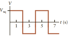
Consider the square wave voltage in Figure Q22.8. What is its frequency?
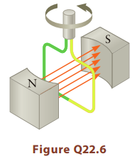
Suppose the loop in the generator in Figure Q22.6 is square and the length of each side of the loop is increased by a factor of two. By what factor will the AC voltage change?
Suppose the magnetic field B in the generator in Figure Q22.6 is reduced in magnitude by a factor of three. By what factor will the AC voltage change?(a) The voltage increases by a factor of three.(b) The voltage decreases by a factor of three.(c) The voltage increases by a factor of nine.(d) The
Make a graph of an AC voltage versus time that corresponds to a frequency of 300 Hz and an rms value of 45 V. Be sure to label the axes of your graph.
Some clocks that are powered by an AC voltage use the AC frequency to keep time. The power company makes this possible by arranging to have precisely the correct number of cycles that occur every day, which keeps such clocks from gaining or losing time over long periods.(a) How many cycles of AC
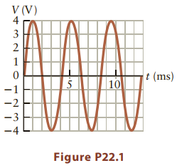
Figure P22.1 shows the AC voltage produced by a particular source. Estimate(a) the frequency of this voltage,(b) the amplitude of this voltage,(c) the rms value of this voltage.(d) If this AC voltage were attached to a lightbulb, would you notice the flicker of the bulb? V (V) 3 t (ms) |10 -1
When applying Kirchhoff’s loop rule to an AC circuit, one assumes the current in the loop is the same through all circuit elements at any particular instant. Changes in current travel at the speed of light (see Chapter 23), so a certain amount of time is actually required for the AC changes to
For an ideal generator, the electrical energy generated equals the work W done in making the shaft rotate. For a real generator, is the electrical energy greater than, equal to, or less than W? Explain.
Some resistors are made from a coil of wire. What is the best way to model the circuit behavior of such a resistor? Choose one answer and explain.(a) As an ideal resistor in series with an ideal inductor?(b) As an ideal resistor in parallel with an ideal inductor?(c) As an ideal resistor in
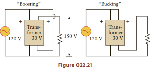
Sometimes an electrical device may need an input voltage that is a few percent higher or lower than the supply voltage. A boosting transformer connects the output coil with the input voltage (here, a 120-V AC source) as shown on the left in Figure Q22.21.(a) Draw the sine waveforms of the input and
Although transformers are AC devices, is there some way to test a transformer to see if it works with a battery? Explain.
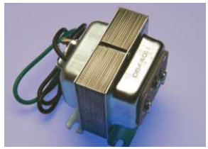
In actual transformers (Fig. Q22.19), the iron cores are actually comprised of thin sheets of metal laminated together with insulating layers in between. Why would the cores be made this way?Figure 22.19
How is a phasor different from a vector? Is the emf a vector quantity?
An LCR circuit with a resonant frequency of 40 Hz is connected to a standard U.S. wall outlet of 120 V AC. Does the current in the circuit “lag” or “lead” the emf? That is, does the current have its maximum before or after the maximum in the voltage?
The equations describing an LC oscillator are very similar in form to those describing the mechanical harmonic oscillator of a mass on a spring. Identify the term in the equation for the mechanical oscillator that plays the role of C. What term plays the role of L? How are these corresponding pairs
An LC circuit is called an oscillator. What, physically, is oscillating in such a circuit? What variables are periodic?
A capacitor is connected in parallel with an inductor, and this circuit is connected to an AC voltage source of frequency f. It is found that the impedance of this circuit increases if the frequency is increased by a small amount. Is f above or below the resonant frequency of the circuit? Explain.
Consider the circuit in Figure Q22.13.(a) Draw equivalent circuits that apply at high and low frequencies.(b) Estimate the ratio Vout/Vin at high and low frequencies.(c) Explain how this circuit acts as a filter that blocks high frequencies but lets low frequencies pass. It is one type of
The reactance of an inductor is given by XL = 2pfL. Show that this reactance has units of ohms. Explain why it makes sense to compare the reactance of an inductor with the resistance of a resistor.
Show that the reactance XC of a capacitor has units of ohms. Explain why it makes sense to compare the reactance of a capacitor with the resistance of a resistor.
If the voltage across a capacitor is V = Vmax sin(2πft), the charge on the capacitor is also proportional to sin(2πft) (see Eq. 22.17). The current through the capacitor in this case is given by I = Imax sin(2πft + π/2); hence, the phase angle is ϕ = π/2 radians relative to the voltage.
Consider two AC voltage sources connected in series with voltages V1 = V1, max sin(2πft) and V2 = V2, max sin(2πft p/4), and V1, max V2, max 30 V. Show that these two sources in series are equivalent to a single source with Vseries = Vequiv sin(2πft + ϕ) and find the values
Most AC voltage sources produce a voltage that varies sinusoidally with time, but some produce a “square wave” as sketched in Figure Q22.8. Use the general definition of rms voltage to find the relation between the amplitude of the square wave and the rms voltage. That is, if the square wave
Discuss why it is relatively easy to change the amplitude of an AC voltage to a higher or lower value, but why it is difficult to change its frequency.
The AC generator described in Figure Q22.6 (and in Section 22.1) uses a rotating coil to produce an AC voltage through electromagnetic induction as described by Faraday’s law.(a) Explain how this approach can produce a voltage whose frequency is equal to the rotation frequency of the shaft.(b)
An AC source with a frequency of 60 Hz is connected to a lightbulb. The instantaneous brightness of the lightbulb depends on the magnitude of the instantaneous current. Explain why the brightness of a bulb can flicker (i.e., oscillate with time) and find the frequency of the flicker. Why don’t we
Figure Q22.4 shows an AC voltage source connected to a resistor in series with an unknown circuit element hidden in a box. The box might contain a single resistor, a single capacitor, or a single inductor.(a) If the magnitude of the impedance as measured between points A and B increases as the
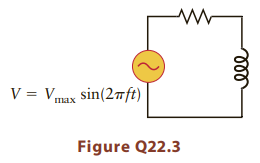
A resistor is connected in series with an inductor (Fig. Q22.3). If the frequency of the AC voltage source is increased while its amplitude Vmax is kept fixed, does the current amplitude increase, decrease, or stay the same? V = Vmax sin(2ft) пах Figure Q22.3
An AC circuit contains a capacitor in series with a resistor. If the frequency of the voltage source is increased while its amplitude is held fixed, does the current amplitude increase, decrease, or stay the same?
Explain in words why(a) the reactance of a capacitor decreases as the frequency increases(b) the reactance of an inductor increases as the frequency increases.
Some cars, such as the Toyota Prius, have what are called regenerative brakes. In these braking systems, the kinetic energy of the car is stored in some fashion as the car is brought to a stop. That energy can then later be “reused” to run an electric motor and hence propel the car. Suppose a
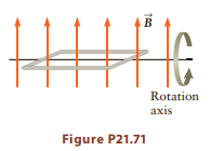
The Earth’s magnetic field is approximately 5x10⁻⁵ T. Suppose a square coil of edge length 0.10 m is rotated with frequency f = 400 Hz about an axis perpendicular to the Earth’s field (Fig. P21.71). The induced emf in this coil will vary with time according to V = V0 sin(2πft). What is the
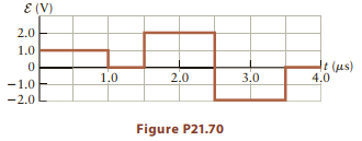
An inductor (L = 50 μH) is subjected to a time-varying current. The emf then produced by the inductor is graphed in Figure P21.70. The initial current is 40 mA. Plot the corresponding current as a function of time. Assume the potential of the supply voltage is positive so that a decrease in
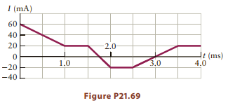
An inductor (L = 80 mH) is subjected to a time- varying current according to the graph in Figure P21.69. Plot the corresponding emf as a function of time. What is the highest potential difference produced? What is the lowest? Assume the potential of the supply voltage is positive so that a
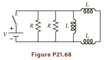
The circuit in Figure P21.68 has two identical resistors and three identical inductors. If L = 30 mH, what value must R have to give a time constant of 50 ms? ll ele Figure P21.68
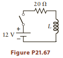
The switch in Figure P21.67 is closed, and 5.5 μs later the current is measured to be 0.10 A.(a) What is the inductance L?(b) What is the maximum current in this circuit?(c) When is the current half of this maximum? 20 Ω ww 12 V -- Figure P21.67
Consider an RL circuit with resistance 100Ω and inductance 200 mH.(a) If the battery is removed from the circuit and replaced by a connecting wire to complete the circuit, how long would it take for the potential difference across the resistor to drop to 37% of its initial value?(b) How long
Consider an RL circuit with resistance 45Ω and inductance 250 mH placed in series.(a) If a 10-V battery is connected to the circuit, how long would it take the current to reach 10 mA?(b) What is the voltage drop across the inductor at this time?
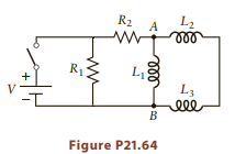
The switch in the circuit shown in Figure P21.64 has been open for a long time. The resistors in the circuit each have a value of 50Ω, the inductors each have a value of 40 mH, and V = 12 V.(a) What is the total equivalent inductance of the circuit between points A and B?(b) What is the current
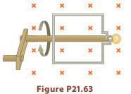
The 3.0-V flashlight bulb and wire loop assembly of Problem 62 is now attached to a wooden dowel with a crank handle as shown in Figure P21.63, and the loop is rotated in a uniform magnetic field of 2.5 T.(a) The crank arm rotates, and for simplicity assume the flux changes from zero to its maximum
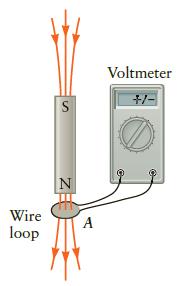
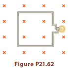
A 3.0-V flashlight bulb is connected to a square loop of wire that measures 60 cm on a side as shown in Figure P21.62. Assume the bulb will only light if the potential across its terminals is at least 3.0 V. The loop is oriented perpendicular to a uniform magnetic field of 2.5 T. The magnetic field
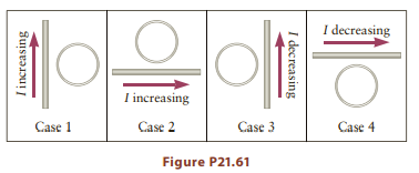
Figure P21.61 shows four configurations of a wire loop placed near a long, straight wire with a time-varying current. Determine the direction of(a) the induced magnetic field in the wire loop (into or out of the page) and(b) the induced current (clockwise or counterclockwise) for each configuration
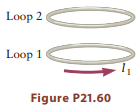
A loop of wire (loop 1) lies in a horizontal plane. A second loop (loop 2) of the same size is positioned above loop 1 and is also oriented horizontally (Fig. P21.60). The current in loop 1 is constant and counterclockwise as viewed from above. If loop 2 falls toward loop 1, what is the direction
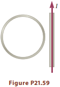
A long, straight wire carrying a current I is next to a wire loop, with the straight wire lying in the plane of the loop (Fig. P21.59). The current I is increasing with time. What is the direction of the induced current in the loop, clockwise or counterclockwise as viewed in the figure?
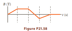
A loop of wire is placed in a magnetic field that varies with time according to the graph in Figure P21.58. Assume the loop is oriented perpendicular to the magnetic field. Sketch the graph for the induced emf in the loop for the same time intervals. B (T) t (s) Figure P21.58
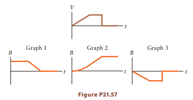
A loop of wire is placed in a time-varying magnetic fi eld B, inducing an emf in the loop whose magnitude varies with time as sketched in Figure P21.57 (top). Which of the graphs below shows how B varies with time? Graph 1 Graph 2 Graph 3 B B Figure P21.57
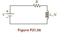
A battery of emf V is connected in series with a resistor of resistance R and an inductor with inductance L and number of turns N as sketched in Figure P21.56. After the current has been fl owing for a long time, the energy stored in the inductor is PE1.(a) If R is increased by a factor of two, how
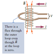
In Section 21.8, we mentioned that an emf is induced in a distant coil or current loop via an electromagnetic wave. For the case in Figure 21.32, this electromagnetic wave travels from the inner solenoid to the outer loop. In a vacuum, this wave travels at a speed c = 3.00x10⁸ m/s. Calculate the
A metal detector uses a coil to find pieces of metal that are buried or otherwise obscured. When a piece of metal is moved near a metal detector’s coil, an emf is induced in the coil. All else being equal, the induced emf is largest for metals that behave as permanent magnets (Chapter 20) such as
A guitar string can vibrate at different frequencies, depending on how it is held (Chapter 12). Consider a string that is being played at either 400 Hz or 800 Hz. If everything else is kept the same, how do the induced emfs at the two frequencies compare? That is, which one is larger, and by what
The pickup coil in an electric guitar contains 10,000 turns and has a diameter of 2.0 mm. When the pickup coil is very close to a guitar string, there is a field of magnitude B = 0.10 T in the coil. If this steel string is vibrating at a frequency of 200 Hz, what is the approximate maximum emf
Showing 2900 - 3000
of 4913
First
23
24
25
26
27
28
29
30
31
32
33
34
35
36
37
Last
Step by Step Answers