New Semester
Started
Get
50% OFF
Study Help!
--h --m --s
Claim Now
Question Answers
Textbooks
Find textbooks, questions and answers
Oops, something went wrong!
Change your search query and then try again
S
Books
FREE
Study Help
Expert Questions
Accounting
General Management
Mathematics
Finance
Organizational Behaviour
Law
Physics
Operating System
Management Leadership
Sociology
Programming
Marketing
Database
Computer Network
Economics
Textbooks Solutions
Accounting
Managerial Accounting
Management Leadership
Cost Accounting
Statistics
Business Law
Corporate Finance
Finance
Economics
Auditing
Tutors
Online Tutors
Find a Tutor
Hire a Tutor
Become a Tutor
AI Tutor
AI Study Planner
NEW
Sell Books
Search
Search
Sign In
Register
study help
sciences
college physics reasoning
College Physics Reasoning and Relationships 2nd edition Nicholas Giordano - Solutions
Use the result from Problem 50 to design a generator that produces an induced emf of 500 V. You must choose values for the number of loops and the area of each loop.
A single circular loop of wire of radius r = 2.0 cm rotates at a frequency of 60 Hz in a constant magnetic field of magnitude B = 1.5T. What is the approximate maximum emf induced in this generator?
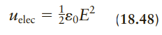
Consider a region of space in which the energy density stored in the magnetic field (Eq. 21.35) is equal to the energy density in the electric field (Eq. 18.48). What is the ratio B/E? Express your result in terms of the fundamental constants ε0 and μ0. = }e,E² (18.48) Uelec
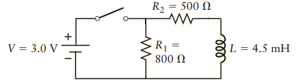
Consider again the circuit in Figure P21.42.(a) Suppose the switch is closed for a very long time. How much energy is stored in the inductor?(b) If the switch is then opened, where does this energy go? Explain.Figure 21.42 R2 = 500 N R1 L = 4.5 mH V = 3.0 V 800 Ω
Consider an MRI (magnetic resonance imaging) magnet that produces a magnetic field B = 1.5 T at a current I = 140 A. Assume the magnet is a solenoid with a radius of 0.30 m and a length of 2.0 m.(a) What is the number of turns of the solenoid?(b) What is its inductance?(c) How much energy is stored
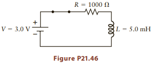
What is the energy stored in the inductor in Figure P21.46 after the switch has been closed for a very long time? R = 1000 N V = 3.0 V L = 5.0 mH Figure P21.46
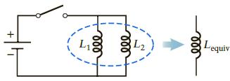
Consider two inductors L1 and L2 connected in parallel as shown in Figure P21.45. These two inductors act as one equivalent inductance Lequiv. To find Lequiv, we first notice that because they are connected in parallel, the voltage across L1 and L2 must be the same, but the rate at which the
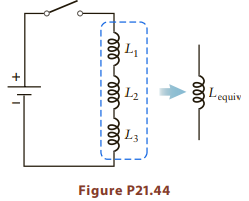
inductors act as one equivalent inductance Lequiv. To find Lequiv, we first note that because the current flows through the inductors sequentially, the factor ΔI/Δt is the same for each.(a) What is the voltage across each inductor? Express your answers in terms of L1, L2, L3, and ΔI/Δt.(b) Use
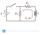
Find the RL time constant for decay of the current in the circuit in Figure 21.25B. Express your answer in terms of the values of the resistances R1 and R2, and the inductance L. R2 R1
The switch in Figure P21.42 is open for a very long time and then closed at t = 0.(a) What is the current through R1 and through R2 immediately after the switch is closed?(b) What is the voltage across the inductor immediately after the switch is closed?(c) After the switch is closed for a very
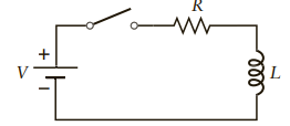
The switch in Figure P21.38 is open for a very long time and then closed at t = 0. What is the voltage across the resistor just after the switch is closed?Figure 21.38 ll
For the circuit in Figure P21.38, if R = 4000Ω, what must the value of L be to have a time constant of 1.5 s?Figure 21.38 ll
Consider again the circuit in Figure P21.38. The switch is first closed for a very long time so that the current through the inductor is constant. The switch is then opened suddenly. What is the voltage across the inductor the instant after the switch is opened?Figure 21.38 ll
Consider an RL circuit (Fig. P21.38) with V = 9.0 V, L = 5.5 mH, and R 1500Ω. After the switch has been left open for a long time, the switch is closed at t = 0.(a) What is the current the instant after the switch is closed?(b) What is the current a very long time after the switch is closed?(c)
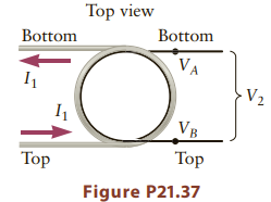
Figure P21.37 shows a top view of a mutual inductor (compare with Fig. 21.19). The two coils are shown in different colors, and the top and bottom wire leads are also indicated.(a) If the current in coil 1 is directed as shown and I1 is increasing, what is the sign of the induced emf V2 in coil 2?
The flux through an inductor with L = 5.0 mH changes at a rate of ΔΦB/Δt 0.0045 Tm2 /s. What is the rate of change ΔI/Δt of the current through the inductor?
An MRI magnet has an inductance of L = 5.0 H. What is the total flux through the magnet’s coils when the current is I = 100 A?
The number of turns in a solenoid is increased by a factor of three without changing the length.(a) By what factor does the magnetic field inside the solenoid change? (b) By what factor does the inductance change?
An inductor has the form of a coil with 2000 turns and a diameter of 1.5 mm. The inductor is placed in a magnetic field perpendicular to the plane of the coil and increasing at a rate of 0.35 T/s. The current in the inductor is zero at t = 0, and then increases to 6.5 mA at t = 1.0 s. What is the
An inductor with L = 1.5 mH is connected to a circuit that produces a current increasing steadily from 1.5 A to 5.6 A over a time of 2.3 s. What is the voltage across the inductor?
An inductor carries a current of 2.5 A, and the magnetic energy stored in the inductor is 0.0035 J. What is the inductance?
Calculate the inductance of a solenoid that is 1.5 cm long and 3.0 mm in diameter, with 300 turns of wire.
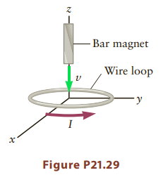
A bar magnet is dropped through a loop of wire as shown in Figure P21.29.(a) When the bar magnet is above the plane of the loop, the current induced in the loop is counterclockwise as viewed from above. Is the orientation of the bar magnet north pole up or south pole up?(b) What is the direction of
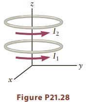
Two circular current loops lie parallel to the x–y plane and are separated by a short distance along z (Fig. P21.28). The currents through these loops are positive if they are counterclockwise as viewed from the +z direction and are negative if they are clockwise.(a) If the current I1 through the
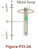
Consider again the metal hoop in Figure P21.26. If a person grabs the hoop and pulls it upward, what is the direction of the magnetic force on the hoop? Give answers when the hoop is at (a) z = +L/2 and (b) z = 0. z Metal hoop N- 2 Figure P21.26
A circular metal hoop is dropped over a bar magnet as sketched in Figure P21.26.(a) Make a qualitative sketch of how the current induced in the hoop varies as a function of its height z. Start with the hoop well above the north pole of the magnet and let it fall all the way to large negative values
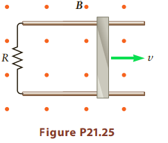
A metal bar of length L = 0.60 m slides freely on two frictionless, horizontal metal rails as shown in Figure P21.25. The entire circuit has resistance R = 200Ω. A magnetic field B = 1.5 T is directed upward, perpendicular to the plane of the drawing and the rectangular area enclosed by the
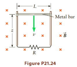
A metal bar of length L is attached to two vertical metal rails as sketched in Figure P21.24. The connections are frictionless, but allow current to flow between the rails and the bar. A constant horizontal magnetic field is directed perpendicular to the area enclosed by the bar and rails.(a) What
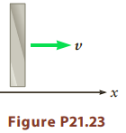
A metal bar is pulled through a region in which the magnetic field is perpendicular to the plane of motion (Fig. P21.23). An emf is induced across the bar, with the top of the bar positive relative to the bottom. Determine the direction of B(vector). Figure P21.23
Suppose the metal rails in Figure P21.14 are now connected on the left so that a complete conducting path (through the bar and the rails) is formed as shown in Figure P21.22.(a) If we wish to find the induced current through the bar, what closed path should we choose for the application of
In Problem 19, a current Iind is induced in the loop. If there is a resistance R in the loop, a certain amount of power P = I2indR will be dissipated in this resistance. Does this energy come from(a) the force exerted on the loop by the magnetic fi eld of the wire,(b) the voltage source that
Consider again the situation in Figure P21.19, but suppose the current I is constant and the loop is pulled away from the wire.(a) What is the direction of the current induced in the loop?(b) This induced current leads to a magnetic force on the loop. What is the direction of this magnetic force?
A long, straight, current-carrying wire passes near a wire loop (Fig. P21.19). The current in the straight wire is directed to the right, and its magnitude is decreasing.(a) What is the direction of the magnetic flux through the loop?(b) Is the magnitude of the flux through the loop increasing or
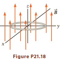
A circular loop of wire lies in the x–y plane so that the axis of the loop lies along z (Fig. P21.18). A magnetic field of magnitude B is parallel to the z axis. This field is positive (i.e., along the z direction) and is the same everywhere within the area of the loop. If B is decreasing with
The loop in Figure P21.16 is rotated out of the plane of the drawing while B is kept constant. You can assume the rotation axis is along the horizontal direction in the figure. (a) Does the magnitude of the flux through the loop increase or decrease with time? (Assume the loop has not had time to
A metal loop is placed in a perpendicular magnetic field as sketched in Figure P21.16.(a) We wish to find the induced current through the loop. What closed path and which corresponding area should we choose for the application of Faraday’s law?(b) What is the direction of the magnetic flux
The Earth’s magnetic field is typically 5x10⁻⁵ T, but fluctuates with time. Suppose the fluctuations in the Earth’s field are sinusoidal with a frequency of 104 Hz and an amplitude of 5% of the magnitude of the Earth’s field. What is the approximate magnitude of the induced emf in a loop of
A metal bar of length L 1.5 m slides along two horizontal metal rails as shown in Figure P21.14. A magnetic field of magnitude B 2.3 T is directed vertically.(a) If the bar is moving at speed v 0.54 m/s, what is the emf induced across the ends of the bar?(b) Which end of the bar is at the higher
A square loop of wire (edge length 45 cm) is found to have an induced emf of 1.2 V at t 0.(a) Assuming the magnetic field is perpendicular to the loop and that the magnitude of the field varies linearly with time, what is the change in the magnetic field from t = 0 to t = 0.10 s?(b) Explain why it
A single loop of wire is placed in a time-varying magnetic field, and an induced emf of 3.5 V is observed. Suppose 25 identical loops with the same orientation are now connected in series. What is the value of the total induced emf?
Consider a magnetic field that varies sinusoidally with time with an amplitude (peak value) of 0.30 T and a frequency of 400 Hz. If a loop of wire of area A 2.5 m2 is oriented perpendicular to this field, what is the approximate value of the maximum induced emf in the loop?
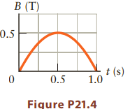
A loop of wire with resistance R = 350Ω and area A = 0.20 m2 is oriented perpendicular to a magnetic field that varies in time as sketched in Figure P21.4. What is the approximate current induced in the loop at(a) t = 0.30 s (b) t = 0.50 s?
Magnetic resonance imaging (MRI) devices use a very large magnet that produces a large magnetic field. Consider an MRI magnet that can accommodate a person. Typically, the person lies down and the field is parallel to her spine (Fig. 21.27). If the magnetic field has magnitude B = 1.2 T, what is
Repeat Problem 7, but assume the leading end of the bar magnet is now the south magnetic pole. Data From problem 7:Consider again the bar magnet and loop in Figure P21.6. Make a qualitative sketch of the current through the loop as a function of time. Assume the bar magnet starts on the far
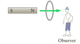
Consider again the bar magnet and loop in Figure P21.6. Make a qualitative sketch of the current through the loop as a function of time. Assume the bar magnet starts on the far left and continues to the far right and take a clockwise current as viewed from the right as positive. Figure 21.6 S
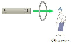
A bar magnet is thrust into a loop of wire as sketched in Figure P21.6. Before the magnet reaches the center of the loop, what is the direction of the induced current as seen by the observer on the right, clockwise or counterclockwise? Figure 21.6 Observer
Consider again the loop of wire described in Problem 4. What is the approximate magnitude of the induced emf at(a) t = 0(b) t = 0.7 s(c) How are the signs of these two emfs related? B (T) 0.5 t (s) 1.0 0.5 Figure P21.4
The magnetic field in a particular region is independent of position, but varies in time as sketched in Figure P21.4. If a loop of area 0.24 m2 is oriented perpendicular to this magnetic field, what is the approximate magnitude of the flux through the loop at t = 0.25 s? B (T) 0.5 t (s)
The magnetic flux through a loop of wire is ΦB = 5.5 T m2. If the magnetic field has magnitude B = 0.85 T, what is the smallest possible value for the area of the loop?
Suppose the wire loop in Problem 1 lies in the x–y plane and the magnetic field now makes an angle of 60° with the z-axis. Find the magnitude of the magnetic flux.
A rectangular loop of wire that is 35 cm wide and 15 cm long is placed in a region where the magnetic field is B = 1.2 T and directed perpendicular to the plane of the loop. What is the magnitude of the magnetic flux through the loop?
The roads near many traffi c lights contain buried sensors that detect when a car is present (waiting at a stop light). These sensors are large loops of wire just beneath the surface of the road.(a) Explain how they can use the induced emf described by Faraday’s law to detect the presence of a
Use the result for the current in an RL circuit in Equation 21.26 to derive the voltage across the inductor as given in Equation 21.28. H,N²A (21.21) VL = Ve- (21.28)
The induced emf is an electric potential difference, so it should have units of volts (V). Show that the right-hand side of Faraday’s law (Eq. 21.5) does indeed have the correct units. - BА |АФв — Ф — Ф, — (21.15)
In an electric circuit containing inductors, the largest induced voltage usually occurs just after a switch is opened or closed. Explain why.
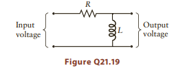
In Chapter 19, we explained how an RC circuit could be used as a filter. The RL circuit in Figure Q21.19 can also be used as a filter. Give a qualitative argument to explain why this circuit will fi lter out rapid fluctuations in the input voltage. Input Output voltage voltage Figure Q21.19
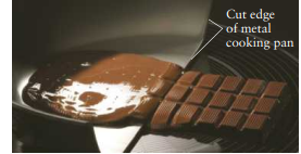
An alternative to gas or electric stove burners, which have an energy transfer effi ciency of less than 50%, are magnetic induction cooktops (Fig. Q21.18), which can be 90% effi cient. The “burner” surface does not get hot at all; only the pan gets hot. The main component of an induction range
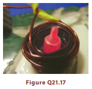
When a large, time- varying current fl ows through a coil, a piece of steel placed within the coil will quickly become red hot (Fig. Q21.17). Why? If a piece of copper were placed in the coil, would the effect be the same? Explain. Figure Q21.17
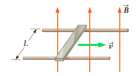
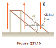
You are hired by an amusement park and asked to design a ride similar to that sketched in Figure Q21.16. A horizontal metal rod slides along two sloped, frictionless rails with a constant magnetic fi eld directed as shown. A rider sits on the bar and slides down along the rails. Magnetic induction
The demonstration described in Question 14 often has some additional components, sometimes including tubes of aluminum and lead with the exact dimensions of the copper tube. The magnet falls at a different rate through the different tubes. Why? Rank the tubes from least to greatest according to the
A popular classroom demonstration of Lenz’s law involves a vertical copper tube and a permanent magnet that fi ts very loosely inside the tube. The instructor fi rst shows that a permanent magnet is not attracted to the copper. The magnet is then dropped down the tube and takes a surprisingly
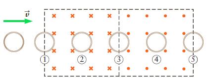
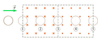
Consider again the copper loop in Figure Q21.12, but this time assume the loop has constant acceleration. Again determine the direction of the current (if any) induced in the copper loop at each point 1 through 5 along its path. Again assume the field is uniform inside the two dashed rectangles and
A loop of copper moving with constant velocity passes through regions of magnetic fi eld as indicated in Figure Q21.12.(a) Determine the direction of the current (if any) induced in the copper loop at each point, 1 through 5, along its path. Assume the fi eld is uniform and of constant magnitude
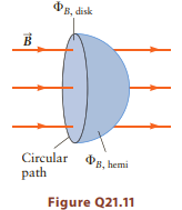
Consider a circular path as sketched in black in Figure Q21.11. This path forms the boundary for a disk and for a hemisphere as well as many other possible surfaces. If the magnetic flux through the disk is ΦB, disk and the flux through the hemisphere is ΦB, hemi, how are these two fluxes
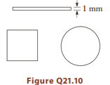
You are given a length L of wire and told to form it into a current loop so as to produce the maximum possible emf when the loop is placed in a time-varying magnetic fi eld. You investigate the three loop geometries in Figure Q21.10: a long, thin rectangle; a square; and a circle. Which one will
Faraday and many other scientists expected that there should be a certain symmetry between electric and magnetic phenomena. Is there a magnetic analog of electric charge? That is, is there such a thing as “magnetic charge”?
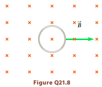
A conducting loop is pulled at constant velocity through a region in which the magnetic field is constant, both inside and outside the loop (Fig. Q21.8). Explain why the induced emf is zero. х х х *B х х х х х х х х Figure Q21.8 х х х х х х х х х х х
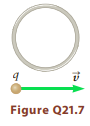
A moving charged particle produces an electric current and hence a magnetic fi eld. Suppose a positively charged particle passes by a circular current loop as sketched in Figure Q21.7, with the loop and the particle’s path lying in the same plane. Make a qualitative sketch of the current through
Many trains use “magnetic brakes.” Explain using Faraday’s law how a “braking force” might be produced. Consider the sliding bar in Figure 21.6 and imagine that it is part of the train.
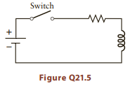
The switch in Figure Q21.5 is initially closed for a very long time. Use Faraday’s law to explain why there can be sparks when the switch is opened. Assume the switch contacts involve two pieces of metal that are pulled apart. Switch Figure Q21.5
The inductance L of a solenoid is proportional to the square of the number of turns, whereas the energy stored in the solenoid PEind is proportional to L.(a) If the length of the solenoid is doubled, by what factors do L and PEind change?(b) Explain physically why the factors in part (a) are larger
Modern coin vending machines use a confi guration of magnets to help sort appropriate currency from fake or foreign coins. When a coin is dropped through the slot, it passes within a few millimeters of the magnets as it falls. Light sensitive sensors detect the passage of the coin as it breaks a
An aluminum disk is held between the poles of a powerful magnet and then pulled out. The person pulling on the disk feels an opposing force due to currents induced through Faraday’s law. Explain why the magnitude of the force becomes larger as the disk is pulled faster.
Describe an example in which the magnetic flux through a surface is zero and the magnetic field is not zero.
An oxygen ion O-2 is moving with a speed of 300 m/s in a direction perpendicular to a magnetic field of magnitude B. If the acceleration of the O-2 ion is 1.5x10⁹ m/s2, what is B?
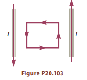
A square current loop is positioned between two long, straight wires carrying currents I as shown in Figure P20.103. All the wires lie in the same plane, and two sides of the loop are parallel to the long wires. If the current loop is placed precisely in the middle between the two long wires, the
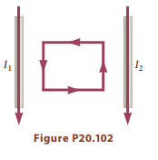
A square current loop is positioned between and equidistant from two long, straight wires carrying currents I1 and I2 as shown in Figure P20.102. All the wires lie in the same plane, and two sides of the loop are parallel to the long wires. If I1/I2 > 1 and the current in the loop is
The wires that carry electrical power into the author’s house are buried underground about 0.5 m below the surface, and they typically carry a current of 100 A. Suppose this current is flowing through a single underground wire feeding into the house. If a person is trying to locate the wire using
You are standing 4.5 m directly below a high-voltage power line, and you have a detailed map indicating that the power line runs exactly north–south. Your compass needle does not align with the power line, however, but instead makes an angle of 32° toward the east with respect to the power
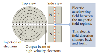
The cyclotron is a device that provides a beam of high velocity charged particles. Consider the electron-accelerating cyclotron depicted in Figure P20.99. Two semicircular magnets provide a uniform magnetic field of 5.0 mT between the poles; in addition, an electric potential difference of 220 V is
An electron enters a bubble chamber and produces a spiral track like that shown on the left in Figure Q20.13. The magnetic field is directed into the page, and the electron had an initial velocity of 2.7 3x10⁸ m/s.(a) If the initial radius of the electron’s trajectory is 5.0 cm, what is its
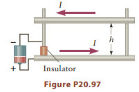
conducting rod of mass 20 g and length 45 cm has holes drilled near each end so that it is free to slide in a vertical direction along two conducting rails as shown in Figure P20.97. A current of 200 A is made to flow through an identical rod at the bottom of the assembly and return through the
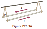
Two aluminum rods of length 75 cm and mass 50 g are suspended by non conducting cables of length 10 cm as shown in Figure P20.96. The rods are part of a circuit (not shown) that supplies a current I through each rod as shown. If the angle between the two end cables is 4.0°, what is the magnitude
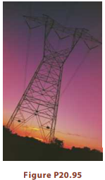
Electric power is transmitted from the generation plant to a municipality via high-voltage power lines such as those connected to the tower in Figure P20.95. Consider a case with towers typically placed at 0.50-km intervals, with three separate lines, spaced 20 m apart and operating at a high
This problem leads you through a study of electric and magnetic fields as viewed by two different observers, that is, in two different reference frames. Suppose a charge q1 is moving with a constant velocity v1(vector) (Fig. P20.94) and that its trajectory takes it to within a distance L of
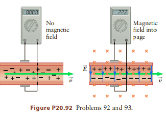
Consider a blood-flow sensor placed around the artery in Figure P20.92. Assume the artery has a radius of 3.0 mm and the magnetic field is B = 0.050 T.(a) If the blood speed is 25 cm/s, what is the magnitude of the electric potential difference across the artery?(b) Which side of the blood vessel
Blood-flow meter. Blood plasma has a high content of Na+ and Cl- ions, and as the blood follows through a blood vessel, the ions travel along at the same speed as the fluid (Fig. P20.92, left). One method of measuring the blood’s velocity is to place the vessel in a magnetic field and then
Suppose the Earth’s magnetic field is produced by a single loop of wire that has a radius of RE, where RE is the radius of the Earth, and assume this loop lies in the equatorial plane. Estimate the current that must flow in this loop to produce a field equal to the Earth’s field at the center
The Earth’s magnetic field has a magnitude of approximately 5.0x10⁻⁵ T, and in New York City this field is directed toward the north geographic pole. If a proton is traveling in an easterly direction with a speed of 600 m/s, what are the magnitude and direction of the magnetic force on the proton?
Based on the results of Problem 88, the U.S. Navy has developed ways to make the magnetic field from its own submarines as small as possible. One way is by wrapping a solenoid around the hull and passing a current through the solenoid so that the field produced by the solenoid approximately cancels
The U.S. Navy can detect a submarine by measuring the magnetic field produced by its metal hull (usually made of a magnetic metal). For the purpose of calculating its magnetic field, model a submarine as one large current loop located at the middle of the submarine carrying 8000 A, as calculated in
Consider the solenoid discussed in Example 20.8. What value of current is required to give a field of magnitude B = 1.0 T? Would this value be practical? Why or why not?
A solenoid has a length of 15 mm and a radius of 0.25 mm, and consists of 5000 circular turns. If a current of 0.35 A is passed through the solenoid, what is the magnetic field at the center (inside the solenoid)?
Design a solenoid that will produce a magnetic field of 0.025 T using a current I = 30 A. If the radius of the solenoid is 10 cm and the solenoid is 1.0 m long, how many turns of wire are required?
A typical lightning bolt carries a peak current of 100 kA.(a) Estimate the peak magnetic field a distance of 500 m from where the lightning bolt strikes the ground.(b) If you have a device that can measure magnetic fields as small as B = 100 pT (10-10 T), how far can you be from the lightning bolt
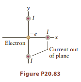
Three very long wires are directed perpendicular to the plane of Figure P20.83. Each passes through the x–y plane a distance L from the origin, and each carries a current I that is directed out of the plane of the drawing. An electron is at the origin and has a velocity directed along +x. What is
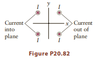
Four very long wires are directed perpendicular to the plane of Figure P20.82. The points where these wires cross the plane of the drawing form a square of edge length 0.45 m, and each wire carries a current of magnitude 2.5 A. Find the magnetic field at the center of the square (i.e., at the
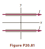
Two long, straight wires lie in the x–y plane and are parallel to the x direction as shown in Figure P20.81. The wires are both a distance of 2.0 m from the origin, and each wire carries a current of 25 A in the +x direction. Find the magnitude of the magnetic field at the point x = 0, y =
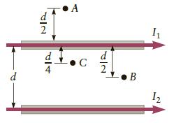
Consider again the two wires in Figure P20.79. For what value of the ratio I1 /I2 is the magnetic field zero at(a) Point A,(b) Point B,(c) Point C? Do your answers to this problem depend on the value of d? A d 2 d C d B I2 一2 す
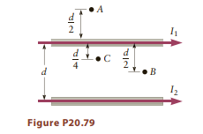
Consider two long, straight, parallel wires (Fig. P20.79) carrying currents I1 = I2. At which point A, B, or C in the figure will the total magnetic field be largest? -•C •B Figure P20.79
Showing 3000 - 3100
of 4913
First
24
25
26
27
28
29
30
31
32
33
34
35
36
37
38
Last
Step by Step Answers