New Semester
Started
Get
50% OFF
Study Help!
--h --m --s
Claim Now
Question Answers
Textbooks
Find textbooks, questions and answers
Oops, something went wrong!
Change your search query and then try again
S
Books
FREE
Study Help
Expert Questions
Accounting
General Management
Mathematics
Finance
Organizational Behaviour
Law
Physics
Operating System
Management Leadership
Sociology
Programming
Marketing
Database
Computer Network
Economics
Textbooks Solutions
Accounting
Managerial Accounting
Management Leadership
Cost Accounting
Statistics
Business Law
Corporate Finance
Finance
Economics
Auditing
Tutors
Online Tutors
Find a Tutor
Hire a Tutor
Become a Tutor
AI Tutor
AI Study Planner
NEW
Sell Books
Search
Search
Sign In
Register
study help
computer science
digital systems principles and application
Digital Systems Principles And Application 12th Edition Ronald Tocci, Neal Widmer, Gregory Moss - Solutions
What kind of register can have a complete binary number loaded into it in one operation, and then have it shifted out one bit at a time?
True or false: In an asynchronous counter, all FFs change states at the same time.
Which Altera megafunction library folder contains LPM_COUNTER?
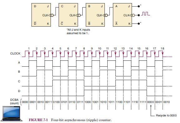
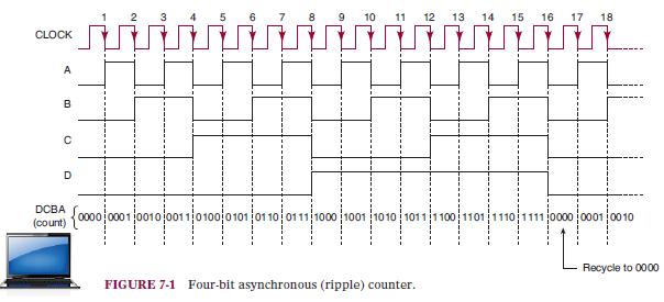
The counter in Figure 7-1 starts off in the 0000 state, and then clock pulses are applied. Some time later the clock pulses are removed, and the counter FFs read 0011. How many clock pulses have occurred?Figure 7-1 CLOCK B C B PEPE CLKO CLKO K B K D D CLK O K с "All J and K inputs assumed to be
What type of table is used to describe a counter’s operation?
Explain why a ripple counter’s maximum frequency limitation decreases as more FFs are added to the counter.
Describe how to connect HDL modules together to create a digital system.
Which shift-register counter requires the most FFs for a given MOD number?
What is the advantage of a synchronous counter over an asynchronous counter? What is the disadvantage?
What FF outputs should be connected to the clearing NAND gate to form a MOD-13 counter?
What is the fundamental difference between a counter and a state machine?
Which classifications for data movement can be implemented by a shift register using an LPM_COUNTER megafunction?
Write a HDL expression that can implement a shift left of an eight-bit array reg[7..0] with serial input dat.
What is meant when we say that a counter is presettable?
What does it mean for a ring counter to self-start?
Name two factors that determine how long a pulse from a digital oneshot will last.
Describe the decoding gate needed to produce a LOW output when aMOD-64 counter is at the count of 23.
What tool is useful in the analysis of synchronous counters?
Draw a binary counter that will convert a 64-kHz pulse signal into a 1-kHz square wave.
What information is contained in a PRESENT state/NEXT state table?
Assume that the counter in Figure 7-1 is holding the count 0101. What will be the count after 27 clock pulses?Figure 7-1 CLOCK A B Ο D DCBA (count) 10 11 12 13 14 15 16 17 18 {000000010010001101000101 οι το οιτι 1000 2001 το το 1011 1100 1101 1110 1111 000 00010010 FIGURE 7-1 Four-bit
True or false: A serial in/parallel out register can have all of its bits displayed at one time.
How do you define the features and modulus for an LPM_COUNTER?
What is the difference between describing a counter and describing a state machine in an HDL?
What circuit changes will convert a synchronous, binary up counter into a binary down counter?
Describe the difference between asynchronous and synchronous presetting.
Which lines of Figure 7-92 ensure that the ring counter self-starts?Figure 7-92 123 2 4 5 6 7 8 9 10 11 12 13 14 15 16 SUBDESIGN fig7_92 clk q[3..0] ( > VARIABLE ff [3..0] ser_in BEGIN END; ff[].clk clk; IF ff[3..1].q- B"000" THEN ser in Vcc; - ELSE ser in- GND; END IF; ff [3..0].d (ser_in,
Why is it necessary to reload the current data during the hold data mode on a shift register?
Describe the function of the C̅L̅R̅ input.
For the one-shots shown in this section, are the counters loaded synchronously or asynchronously?
What determines the count sequence for a counter circuit?
Assume that a five-bit binary counter starts in the 00000 state. What will be the count after 144 input pulses?
What information is contained in the circuit excitation table?
What type of register can have data entered into it only one bit at a time, but has all data bits available as outputs?
Explain the difference between an asynchronous clear and a synchronous clear for a counter.
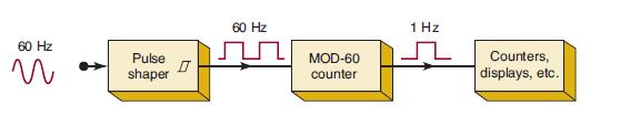
The first step involved in building a digital clock is to take the 60-Hz signal and feed it into a Schmitt-trigger, pulse-shaping circuit* to produce a square wave, as illustrated in Figure 7-3. The 60-Hz square wave is then put into a MOD-60 counter, which is used to divide the 60-Hz frequency by
What would be the MOD number of the counter if three more FFs were added?
What counter features must be included to synchronously cascade counter modules together?
How can a ring counter be converted to a Johnson counter?
What logic signal drives the J, K inputs of the MSB flip-flop for the counter of question 2?
What is the MSB output frequency of a decade counter that is clockedfrom a 50-kHz signal?
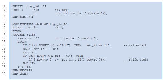
Which lines of Figure 7-94 ensure that the ring counter self-starts?Figure 7-94 1 2 3 4 DHZBGE62992 10 5 6 ARCHITECTURE vhdl OF fig7_94 IS 7 SIGNAL ser_in :BIT; 8 BEGIN 9 PROCESS (clk) 11 12 13 14 15 16 17 ENTITY fig7 94 IS PORT ( clk q 18 19. 20 END fig7_94; IN BIT; :OUT BIT VECTOR (3 DOWNTO
If the actual binary states for a state machine are not defined in the HDL code, how are they assigned?
True or false: The 74HC161 cannot be preset while C̅L̅R̅ is active.
What is the advantage of loading a counter synchronously?
What counter characteristic is described by saying that it is self-correcting?
A 10-bit ripple counter has a 256-kHz clock signal applied.(a) What is the MOD number of this counter?(b) What will be the frequency at the MSB output?(c) What will be the duty cycle of the MSB signal?(d) Assume that the counter starts at zero. What will be the count in hexadecimal after 1000 input
True or false: The synchronous counter design procedure can be used for the following sequence: 0010, 0011, 0100, 0111, 1010, 1110, 1111, and repeat.
In what type of register do we store data one bit at a time and have access to only one output bit at a time?
What is the function of cout for an LPM_COUNTER?
Which method describes the circuit’s operation using cause-and-effect relationships?
(a) Determine fmax for the synchronous counter of Figure 7-5(a) if tpd for each FF is 50 ns and tpd for each AND gate is 20 ns. Compare this value with fmax for a MOD-16 ripple counter.(b) What must be done to convert this counter to MOD-32?(c) Determine fmax for the MOD-32 parallel counter.
True or false:(a) The outputs of a ring counter are always square waves.(b) The decoding circuitry for a Johnson counter is simpler than for a binary counter.(c) Ring and Johnson counters are synchronous counters.
What is the advantage of using state machine description?
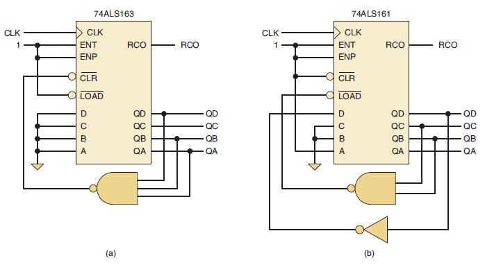
What logic levels must be present on the control inputs in order for the 74ALS162 to count pulses that appear on the CLK?
What is the advantage of loading the counter asynchronously?
A four-bit ripple counter is driven by a 20-MHz clock signal. Draw the waveforms at the output of each FF if each FF has tpd = 20 ns. Determine which counter states, if any, will not occur because of the propagation delays.
How does the parallel data entry differ for the 74165 and the 74174?
The counting of an LPM_COUNTER can be enabled or disabled using either cnt_en or cin. What is the difference between these two controls?
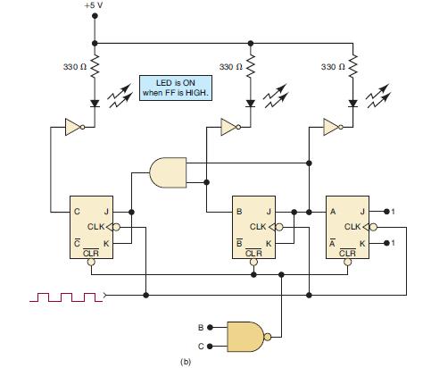
(a) What will be the status of the LEDs when the counter in Figure 7-7(b) is holding the count of five?(b) What will the LEDs display as the counter is clocked by a 1-kHz input?(c) Will the 110 state be visible on the LEDs?Figure 7.7(b) 3300 C +5 V 10 J CLK CLR K LED is ON when FF is
What is the difference between asynchronous clear and synchronous load?
How many FFs are needed in a MOD-16 ring counter? How many are needed in a MOD-16 Johnson counter?
What logic levels must be present on the control inputs in order for the 74HC190 to count down with pulses that appear on the CLK?
What two pieces of information are necessary to detect an edge?
(a) What is the maximum clock frequency that can be used with the counter of Problem 7-5?(b) What would fmax be if the counter were expanded to six bits?Data from Problem 7-5A four-bit ripple counter is driven by a 20-MHz clock signal. Draw the waveforms at the output of each FF if each FF has tpd
How does the CP INH input of the 74ALS165 work?
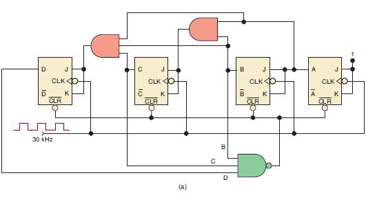
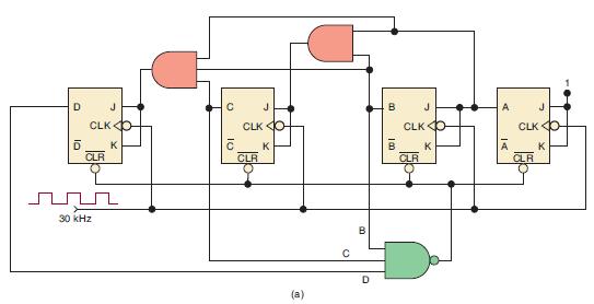
Determine the MOD number of the counter in Figure 7-8(a). Also determine the frequency at the D output.Figure 7-8(a) D CLKO D K CLR O 30 kHz C 10 J CLK O K CLR (a) с B D B 10 J CLKO K CLR A CLK O K CLR
How do you create an asynchronous clear function in an HDL?
What would be the maximum counting range for a four-stage counter made up of 74HC163 ICs? What is the maximum counting range for 74ALS190 ICs?
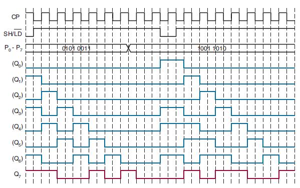
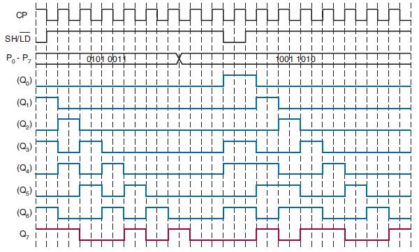
In Figure 7-72 exchange the values on P0 – P7 i.e. swap values 01010011 and 10011010 and redraw the output timing of each Q.Figure 7-72 CP SH/LD P₁-P₁ (°0) o (Q₂) (Q₂) (Q₁) (Q₂) Q7 0011 1001 101 HAH
(a) Draw the circuit diagram for a MOD-32 synchronous counter.(b) Determine fmax for this counter if each FF has tpd = 20 ns and each gate has tpd = 10 ns.
How do you create functions priority in an HDL description of a counter?
Construct a MOD-10 counter that will count from 0000 (zero) through 1001 (decimal 9).
The decade counter in Figure 7-8(b) has a 1-kHz clock applied.(a) Draw the waveforms for each FF output, showing any glitches that may occur.(b) Determine the frequency of the signal at the D output.(c) If the counter is originally at state 1000, what state will the counter be at after 14 clock
(a) Draw the circuit diagram for a MOD-64 synchronous counter.(b) Determine fmax for this counter if each FF has tpd = 20 ns and each gate has tpd = 10 ns.
Repeat Problem 7-9 for the counter of Figure 7-8(a) with a 70-kHz clock.Figure 7-8(a)Data from Problem 7-9The decade counter in Figure 7-8(b) has a 1-kHz clock applied.(a) Draw the waveforms for each FF output, showing any glitches that may occur.(b) Determine the frequency of the signal at the D
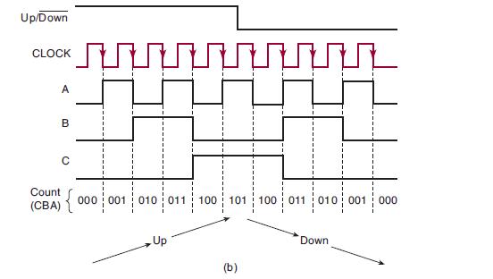
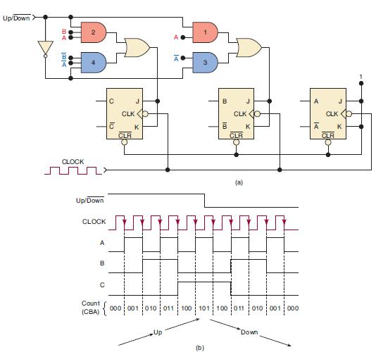
What problems might be caused if thesignal in Figure 7-11(b) changes levels on the NGT of the clock?Figure 7-11(b) Up/Down
In Example 7-3, a MOD-60 counter was needed to divide the 60-Hz line frequency down to 1 Hz. Construct an appropriate MOD-60 counter.Data from Example 7-3The first step involved in building a digital clock is to take the 60-Hz signal and feed it into a Schmitt-trigger, pulse-shaping circuit* to
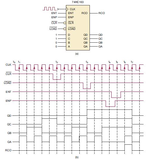
Refer to Figure 7-14, where a 74HC163 has the input signals given in the timing diagram applied. The parallel data inputs are permanently connected as 1100. Assume the counter is initially in the 0000 state, and determine the counter output waveforms.Figure 7-14
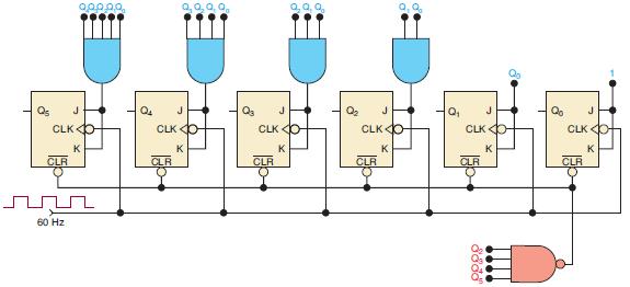
Change the inputs to the NAND gate of Figure 7-9 so that the counter divides the input frequency by 50.Figure 7-9 Q5 CLK CLR 60 Hz 900.00 J K Q₂ CLK O CLR Q3 0, 0, 0, J CLK O K CLR Q₂ J CLKO K CLR Q₁ CLK CLR 8338 J K Qo J CLK O CLR K
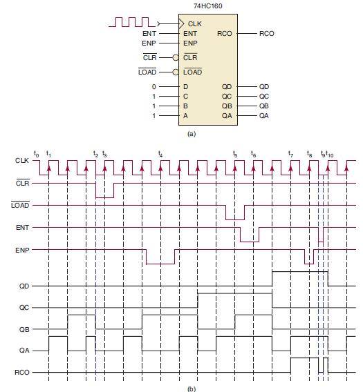
Refer to Figure 7-15, where a 74HC160 has the input signals given in the timing diagram applied. The parallel data inputs are permanently connected as 0111. Assume the counter is initially in the 0000 state, and determine the counter output waveforms.Figure 7-15
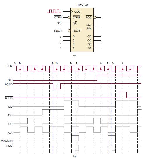
Refer to Figure 7-17, where a 74HC190 has the input signals given in the timing diagram applied. The parallel data inputs are permanently connected as 0111. Assume the counter is initially in the 0000 state, and determine the counter output waveforms.Figure 7-17
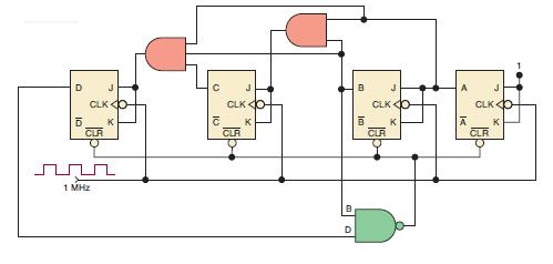
Draw a synchronous counter that will output a 10-kHz signal when a 1-MHz clock is applied.
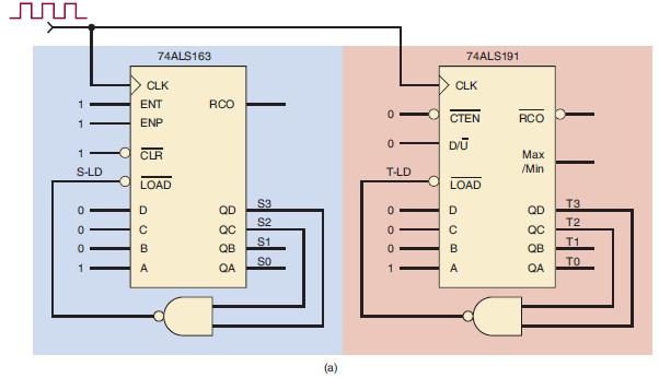
Compare the operation of two counters, one with synchronous load and the other with asynchronous load. Refer to Figure 7-18(a), in which a 74ALS163 and a 74ALS191 have been wired in a similar fashion to count up in binary. Both chips are driven by the same clock signal and have their QD and QC
Draw a synchronous, MOD-32, down counter.
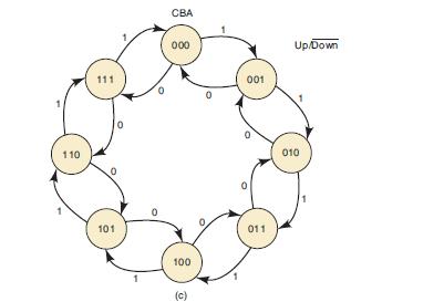
Determine the count sequence of the up/down counter in Figure 7-11 if the INVERTER output were stuck HIGH. Assume the counter starts at 000.Figure 7-11 Up/Down ➤.00 >> lol CLOCK Up/Down CLOCK A B Count (CBA) с с J CLK O C K CLR A Up Ā { 000 001010011 100 B (b) 100 8 J CLK O K CLR (a) 101 100
Draw a synchronous, MOD-16, up/down counter. The count direction is controlled by dir (dir = 0 to count up).
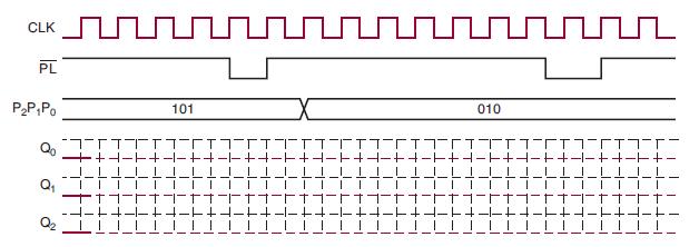
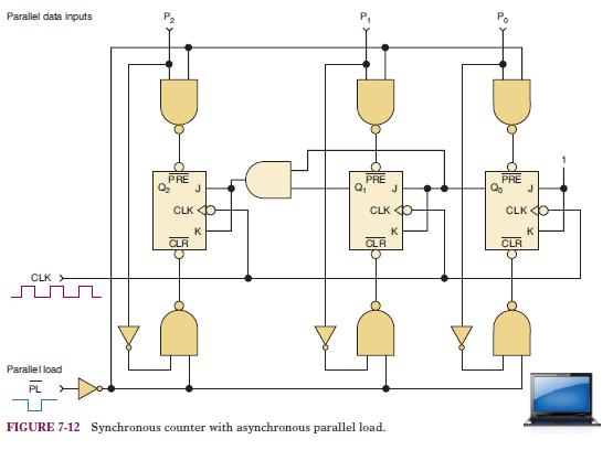
Complete the timing diagram in Figure 7-102 for the presettable counter in Figure 7-12. Note that the initial condition for the counter is given in the timing diagram.Figure 7-102Figure 7-12 CLK PL P2P1P0 Q0 Q1 02 - + 101 TTI IT +--++-++-++ ட * + ri 010 ITT -+4--+ ++-++- JL |_|_| | --- -
How many AND gates are required to decode completely all of the states of a MOD-32 binary counter? What are the inputs to the gate that decodes for the count of 21?
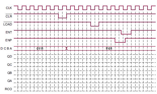
Complete the timing diagram in Figure 7-103 for a 74ALS161 with the indicated input waveforms applied. Assume the initial state is 0000.Figure 7-103 cux CLR LOAD IN3 ENP DCBA QD QC 80 QA RCO | | --L1- -+- |T- TT J_L 110 T ட 7 ||T 1 -ட TI J_ட •___T____T==_TH__T____TH=_T___T___T____THEET-
Design the hours and minutes counters for a digital clock. Use a binary counter for the hours and cascaded BCD counters for the minutes. Since the minutes block and the seconds block of a digital clock will each require MOD-60 counters, we will be able to use the same design for both sections of
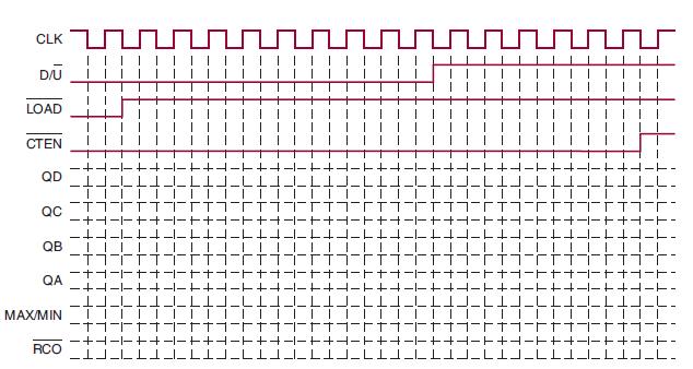
Complete the timing diagram in Figure 7-105 for a 74ALS190 with the indicated input waveforms applied. The DCBA input is 0101.Figure 7-105 CLK G D/U LOAD CTEN QD QC QB QA | | | | | | ||||||||||||| RCO LLI. -+1 -+. MAX/MIN || -T1 III | LI |-++- гт- I 十一 - |
Design the frequency divider circuit to obtain the correct clocking frequency to drive the MOD-60 seconds counter of a digital clock. The system clock frequency is 1 kHz.
Show how to connect the 74ALS174 so that it operates as a serial shift register with data shifting on each PGT of CP as follows: Serial input → Q5 → Q4 → Q3 → Q2 → Q1 → Q0. In other words, serial data will enter at D5 and will output at Q0.
Repeat Problem 7-19 for a 74ALS191 and a DCBA input of 1100.Data from Problem 7-19Complete the timing diagram in Figure 7-105 for a 74ALS190 with the indicated input waveforms applied. The DCBA input is 0101.Figure 7-105 CLK G D/U LOAD CTEN QD QC QB QA | | | | | |
A shift register is often used as a way to delay a digital signal by an integral number of clock cycles. The digital signal is applied to the shift register’s serial input and is shifted through the shift register by successive clock pulses until it reaches the end of the shift register, where it
How would you connect two 74ALS174s to operate as a 12-bit shift register?
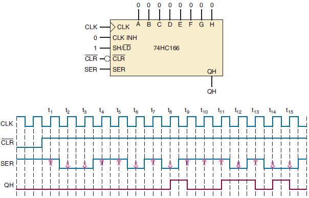
Refer to the IC counter circuit in Figure 7-106(a):(a) Draw the state transition diagram for the counter’s QD QC QB QA outputs.(b) Determine the counter’s modulus.(c) What is the relationship of the output frequency of the MSB to the input CLK frequency?(d) What is the duty cycle of the MSB
Repeat Problem 7-21 for the IC counter circuit in Figure 7-106(b).Data from Problem 7-21Refer to the IC counter circuit in Figure 7-106(a):(a) Draw the state transition diagram for the counter’s QD QC QB QA outputs.(b) Determine the counter’s modulus.(c) What is the relationship of the output
Determine the output signal at Q7 if we connect a 74HC165 with DS = 0 and CP INH = 0 and then apply the input waveforms given in Figure 7-72. P0 – P7 represent the parallel data on P0 P1 P2 P3 P4 P5 P6 P7.Figure 7-72 CP SH/LD Po-P7 (0%) (Q1) (0) (50) (80) 3 언어 0011 1000 1010
Showing 800 - 900
of 1612
First
2
3
4
5
6
7
8
9
10
11
12
13
14
15
16
Last
Step by Step Answers
![123 2 4 5 6 7 8 9 10 11 12 13 14 15 16 SUBDESIGN fig7_92 clk q[3..0] ( > VARIABLE ff [3..0] ser_in BEGIN END;](https://dsd5zvtm8ll6.cloudfront.net/images/question_images/1699/9/4/0/16065530740842d91699940161673.jpg)