New Semester
Started
Get
50% OFF
Study Help!
--h --m --s
Claim Now
Question Answers
Textbooks
Find textbooks, questions and answers
Oops, something went wrong!
Change your search query and then try again
S
Books
FREE
Study Help
Expert Questions
Accounting
General Management
Mathematics
Finance
Organizational Behaviour
Law
Physics
Operating System
Management Leadership
Sociology
Programming
Marketing
Database
Computer Network
Economics
Textbooks Solutions
Accounting
Managerial Accounting
Management Leadership
Cost Accounting
Statistics
Business Law
Corporate Finance
Finance
Economics
Auditing
Tutors
Online Tutors
Find a Tutor
Hire a Tutor
Become a Tutor
AI Tutor
AI Study Planner
NEW
Sell Books
Search
Search
Sign In
Register
study help
engineering
control systems engineering
Control Systems Engineering 7th Edition Norman S. Nise - Solutions
Repeat Problem 48 using MATLAB.Data From Problem 48:Find the closed-loop transfer function of the Unmanned Free-Swimming Submersible vehicle’s pitch control system shown on the back endpapers (Johnson, 1980).
Integrated circuits are manufactured through a lithographic process on a semiconductor wafer. In lithography, similarly to chemical photography, a semiconductor wafer is covered with a photosensitive emulsion and then selectively exposed to light to form the electronic components. Due to
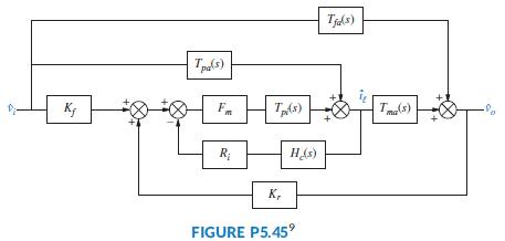
A boost converter is a dc-to-dc switched power supply in which the voltage output is larger than the voltage input. A block diagram for a peak current mode controlled converter (Chen, 2013) is shown in Figure P5.45. Find the transfer function v̂o (s) v̂i (s). Tjds) Tls) R; HAs) K, FIGURE P5.45°
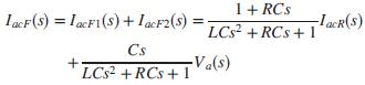
In Problem64 of Chapter 2, a three-phase ac/dc converter that supplies dc to a battery charging system (Graovac, 2001) was introduced. Each phase had an ac filter represented by the equivalent circuit of Figure P2.38. You were asked to show that the following equation gives the s domain
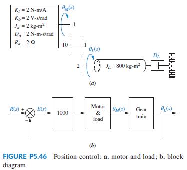
The motor and load shown in Figure P5.46(a) are used as part of the unity feedback system shown in Figure P5.46(b). Find the value of the coefficient of viscous damping, DL, that must be used in order to yield a closed-loop transient response having a 20% overshoot. K, = 2 N-m/A K = 2 V-s/rad J.= 2
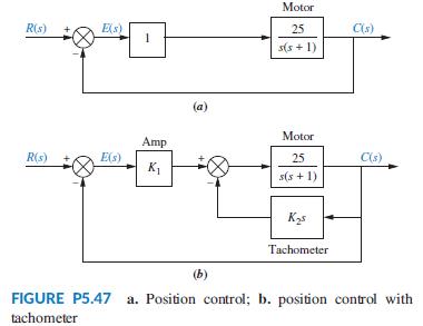
Assume that the motor whose transfer function is shown in Figure P5.47(a) is used as the forward path of a closed-loop, unity feedback system.a. Calculate the percent overshoot and settling time that could be expected.b. You want to improve the response found in Part a. Since the motor and the
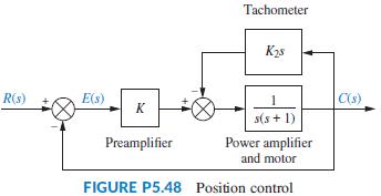
The system shown in Figure P5.48 will have its transient response altered by adding a tachometer. Design K and K2 in the system to yield a damping ratio of 0.69. The natural frequency of the system before the addition of the tachometer is 10 rad/s. Tachometer K2s R(s) E(s) C(s) K s(s + 1) Power
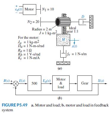
The mechanical system shown in Figure P5.49(a) is used as part of the unity feedback system shown in Figure P5.49(b). Find the values of M and D to yield 20% overshoot and 2 seconds settling time. + eal) Motor N1 = 10 D N2 = 20 Radius = 2 m J= 1 kg-m? Ideal gear 1:1 For the motor: Ja = 1 kg-m2 Da =
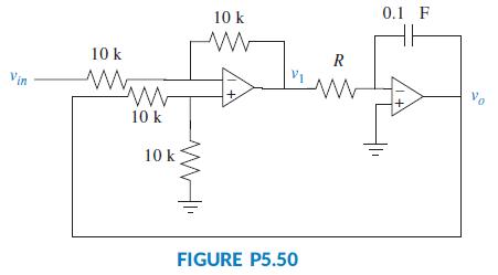
Assume ideal operational amplifiers in the circuit of Figure P5.50.a. Show that the leftmost operational amplifier works as a subtracting amplifier. Namely, v1 = vo - vin.b. Draw a block diagram of the system, with the subtracting amplifier represented with a summing junction, and the circuit of
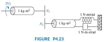
Given the rotational system shown in Figure P4.23, do the following:a. Using the transfer function you derived for that system, G(s) = Θ1(s)/T(s), where Θ1(s) is the angular displacement of the first shaft, find the value of n = N1/N2 that yields a settling time of 10 seconds for a step input in
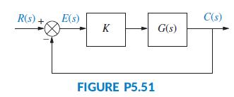
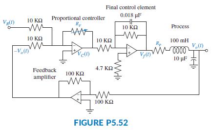
A process is simulated by the second-order passive circuit, shown in Figure P5.52, where the feedback amplifier, controller, and final control element are represented by op-amp circuits.a. Denoting the input and output as R(s) = Vi (s) and C(s) = Vo(s), with R(s) - C(s) = E(s), and noting that the
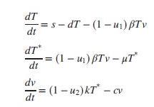
Given the HIV system of Problem 84 in Chapter 4 and repeated here for convenience (Craig, 2004):Express the system in the following forms:a. Phase-variable formb. Controller canonical formc. Observer canonical formFinally,d. Use MATLAB to obtain the system’s diagonalized representation.Data from
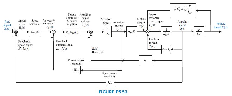
Figure P5.53 shows the block diagram of a possible cascade control scheme for an HEV driven by a dc motor (Preitl, 2007).Let the speed controller GSC(s) = 100 + 40/s, the torque controller and power amp KAGTC(s) = 10 + 6/s, the current sensor sensitivity KCS = 0.5, the speed sensor sensitivity KSS
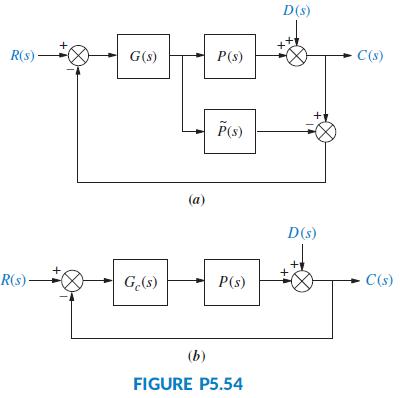
Effective controller design for parabolic trough collector setups is an active area of research. One of the techniques used for controller design (Camacho, 2012) is Internal Model Control (IMC). Although complete details of IMC will not be presented here, Figure P5.54(a) shows a block diagram for
Tell how many roots of the following polynomial are in the right half plane, in the left half-plane, and on the jω-axis:P(s) = s5 + 3s4 + 5s3 + 4s2 + s + 3
What part of the output response is responsible for determining the stability of a linear system?
Tell how many roots of the following polynomial are in the right half plane, in the left half-plane, and on the jω-axis:P(s) = s5 + 6s3 + 5s2 + 8s + 20
What happens to the response named in Question 1 that creates instability?Data From Question 1:What part of the output response is responsible for determining the stability of a linear system?
Using the Routh table, tell how many poles of the following function are in the right half-plane, in the left half-plane, and on the jω-axis. s+ 8 T(s) 5 - s4 +3s3 – 3s2 + 3s – 2
What would happen to a physical system that becomes unstable?
The closed-loop transfer function of a system isDetermine how many closed-loop poles lie in the right half-plane, in the left half-plane, and on the jω-axis. 3 +252 + 7s + 21 T(s) = %3D g5 – 2s4 + 353 – 6s2 + 2s - 4
Why are marginally stable systems considered unstable under the BIBO definition of stability?
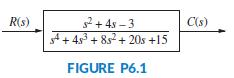
How many poles are in the right half-plane, in the left half-plane, and on the jω-axis for the open-loop system of Figure P6.1? 2+ 4s – 3 4+ 4s + 8s + 20s +15 R(s) C(s) FIGURE P6.1
Where do system poles have to be to ensure that a system is not unstable?
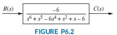
How many poles are in the right half-plane, the left half-plane, and on the jω-axis for the open-loop system of Figure P6.2? R(s) -6 C(s) 6 +- 6s4 + s2 +s-6 FIGURE P6.2
What does the Routh-Hurwitz criterion tell us?
Use MATLAB to find the pole locations for the system of Problem 6.Data From Problem 6:How many poles are in the right half-plane, the left half-plane, and on the jω-axis for the open-loop system of Figure P6.2? R(s) -6 C(s) 6 +- 6s4 + s2 +s-6 FIGURE P6.2
Under what conditions would the Routh-Hurwitz criterion easily tell us the actual location of the system’s closed-loop poles?
Use MATLAB and the Symbolic Math Toolbox to generate a Routh table to solve Problem 3.Data From Problem 3:Using the Routh table, tell how many poles of the following function are in the right half-plane, in the left half-plane, and on the jω-axis. s+ 8 T(s) 5 - s4 +3s3 – 3s2 + 3s – 2
What causes a zero to show up only in the first column of the Routh table?
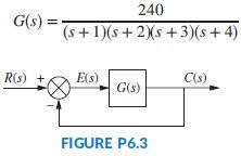
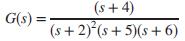
Determine whether the unity feedback system of Figure P6.3 is stable if 240 G(s) %3D (s+1)(s+ 2)s + 3)(s+ 4) R(s) + E(s) C(s) G(s) FIGURE P6.3
What causes an entire row of zeros to show up in the Routh table?
Use MATLAB to find the pole locations for the system of Problem 9.Data From Problem 9:Determine whether the unity feedback system of Figure P6.3 is stable if 240 G(s) %3D (s+1)(s+ 2)s + 3)(s+ 4) R(s) + E(s) C(s) G(s) FIGURE P6.3
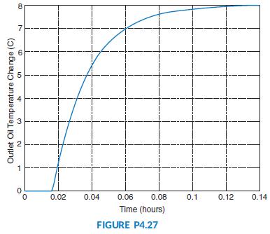
Figure P4.27 illustrates the results of an open-loop step-response experiment performed on a parabolic trough collector setup (Camacho, 2012). In this experiment, the fluid flow on the system is suddenly decreased 1 liter/sec at t = 0 hours, resulting in a temperature increase as shown in Figure
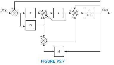
Find the unity feedback system that is equivalent to the system shown in Figure P5.7. R(s) + C(s) s+1 2s 4 FIGURE P5.7
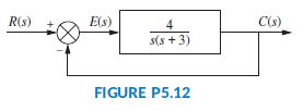
For the system shown in Figure P5.12, find the output, c(t), if the input, r(t), is a unit step. R(s) E(s) 4 C(s) s(s + 3) FIGURE P5.12
When the system matrix is diagonal, what quantities lie along the diagonal?
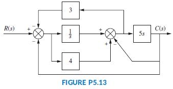
For the system shown in Figure P5.13, find the poles of the closed-loop transfer function, T(s) = C(s)/R(s). 3 C(s) 5s R(s) 4 FIGURE P5.13
What terms lie along the diagonal for a system represented in Jordan canonical form?
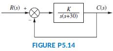
For the system of Figure P5.14, find the value of K that yields 10% overshoot for a step input. R(s) + K C(s) s(s+30) FIGURE P5.14
What is the advantage of having a system represented in a form that has a diagonal system matrix?
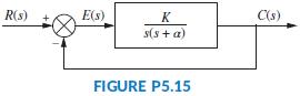
For the system shown in Figure P5.15, find K and α to yield a settling time of 0.12 second and a 20% overshoot. R(s) E(s) K C(s) s(s + a) FIGURE P5.15
Give two reasons for wanting to represent a system by alternative forms.
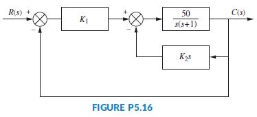
For the system of Figure P5.16, find the values of K1 and K2 to yield a peak time of 1 second and a settling time of 2 seconds for the closed loop system’s step response. R(s) + 50 C(s) K1 s(s+1) FIGURE P5.16
For what kind of system would you use the observer canonical form?
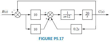
Find the following for the system shown in Figure P5.17:a. The equivalent single block that represents the transfer function, T(s) = C(s)/R(s).b. The damping ratio, natural frequency, percent overshoot, settling time, peak time, rise time, and damped frequency of oscillation. R(s) C(s) 20 10 s+12
Describe state-vector transformations from the perspective of different bases.
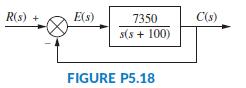
For the system shown in Figure P5.18, find ζ, ωn, percent overshoot, peak time, rise time, and settling time. R(s) E(s) 7350 C(s) s(s + 100) FIGURE P5.18
What is the definition of an eigenvector?
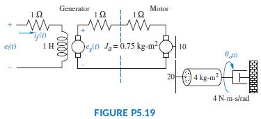
A motor and generator are set up to drive a load as shown in Figure P5.19. If the generator output voltage is eg(t) = Kf if (t), where if (t) is the generator’s field current, find the transfer function G(s) = θo (s)/Ei(s). For the generator, Kf = 2Ω. For the motor, Kt = 2 N-m/A, and Kb = 2
Based upon your definition of an eigenvector, what is an eigenvalue?
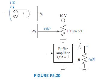
Find G(s) = E0(s)/T(s) for the system shown in Figure P5.20. T(t) for N1 10 V ej(1) N2 1 Tum pot C Buffer amplifier gain = 1 R. egl) FIGURE P5.20
What is the significance of using eigenvectors as basis vectors for a system transformation?
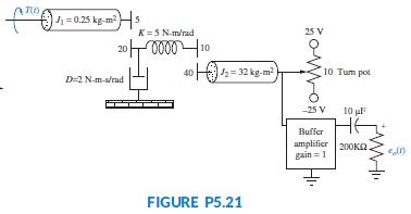
Find the transfer function G(s) = Eo(s)/T(s) for the system shown in Figure P5.21. +1 =0.25 kg-m? K=5 N-m/rad 25 V 20 10 2= 32 kg-m? 10 Tum pot D-2 N-m-s/rad -25 V 10 pF HE Buffer amplifier 200Kn. gain = 1 FIGURE P5.21
Label signals and draw a signal-flow graph for each of the block diagrams shown in the following problems:a. Problem 1b. Problem 3c. Problem 5Data From Problem 1:Data From Problem 3:Data From Problem 5: R(s) + 50 C(s) s+1 2 2 FIGURE P5.1
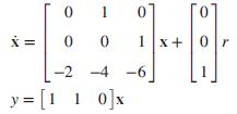
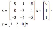
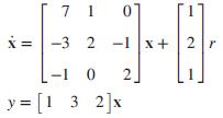
Draw a signal-flow graph for each of the following state equations:a.b.c. -3 1x+1 -3 -4 -5 y = [1 2 0]x
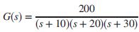
Given the system below, draw a signal-flow graph and represent the system in state space in the following forms:a. Phase-variable formb. Cascade form 200 G(s) (s + 10)(s + 20)(s+ 30)
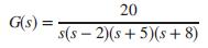
Repeat Problem 24 forData from Problem 24:Given the system below, draw a signal-flow graph and represent the system in state space in the following forms:a. Phase-variable formb. Cascade form 20 G(s) = s(s – 2)(s+ 5)(s+ 8) %3!
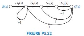
Using Mason’s rule, find the transfer function, T(s) = C(s)/R(s), for the system represented in Figure P5.22. G|(s) G(s) G3(s) G,(s) Rs) C(s) -1 -1 -1 FIGURE P5.22
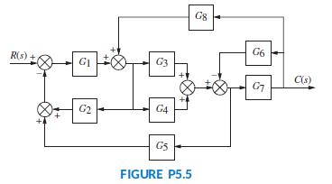
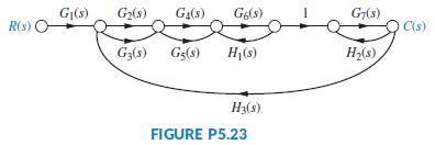
Using Mason’s rule, find the transfer function, T(s) = C(s)/R(s), for the system represented by Figure P5.23. G|(s) G2(s) Ga(s) Ge(s) G(s) R(s) C(s) G3(s) Gg(s) H(s) H2(s) H3(s) FIGURE P5.23
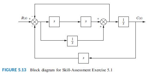
Use Mason’s rule to find the transfer function of Figure 5.13 in the text. R(s) C(s) FIGURE 5.13 Block diagram for Skill-Assessment Exercise 5.1
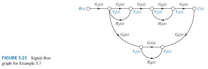
Use block diagram reduction to find the transfer function of Figure 5.21 in the text, and compare your answer with that obtained by Mason’s rule. G,(s) G2(s) G2(s) Gg(s) R(s) C(s) V(s) V3(s) V2(s) V(s) H(s) Gg(s) G7(s) Ve(s) V5(s) FIGURE 5.21 Signal-flow graph for Example 5.7 Ha(s)
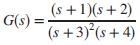
Represent the following systems in state space in Jordan canonical form. Draw the signal-flow graphs.a.b.c. (s +1)(s+ 2) G(s) = (s +3)*(s+4)
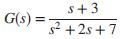
Represent the systems below in state space in phase-variable form. Draw the signal-flow graphs.a.b.c. s+3 G(s) = %3D s2 +2s +7
Repeat Problem 31 and represent each system in controller canonical and observer canonical forms.Data From Problem 31:Represent the systems below in state space in phase-variable form. Draw the signal-flow graphs.a.b.c. s+3 G(s) = %3D s2 +2s +7
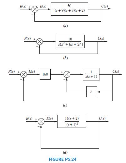
Represent the feedback control systems shown in Figure P5.24 in state space. When possible, represent the open-loop transfer functions separately in cascade and complete the feedback loop with the signal path from output to input. Draw your signal-flow graph to be in one-to one correspondence to
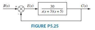
You are given the system shown in Figure P5.25.a. Represent the system in state space in phase-variable form.b. Represent the system in state space in any other form besides phase-variable. R(s) E(s) 30 C(s) s(s + 3)(s + 5) FIGURE P5.25
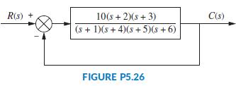
Repeat Problem 34 for the system shown in Figure P5.26.Data From Problem 34:You are given the system shown in Figure P5.25.a. Represent the system in state space in phase-variable form.b. Represent the system in state space in any other form besides phase-variable. R(s) + 10(s + 2)(s + 3) C(s) (s +
Use MATLAB to solve Problem 35.Data From Problem 35:Repeat Problem 34 for the system shown in Figure P5.26.Data From Problem 34:You are given the system shown in Figure P5.25.a. Represent the system in state space in phase-variable form.b. Represent the system in state space in any other form
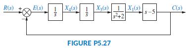
Represent the system shown in Figure P5.27 in state space where x1(t); x3(t); and x4(t), as shown, are among the state variables, c(t) is the output, and x2(t) is internal to X1(s)/X3(s). 1 X(s) X3(s)1 X1(s) s-5 R(s) E(s) C(s) s2+2 FIGURE P5.27
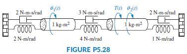
Consider the rotational mechanical system shown in Figure P5.28.a. Represent the system as a signal-flow graph.b. Represent the system in state space if the output is θ2(t). 2 N-m-s/rad 3 N-m-s/rad 2 N-m-s/rad I kg-m? I kg-m? 2 N-m/rad 4 N-m/rad IN-m/rad FIGURE P5.28
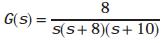
Given a unity feedback system with the forward-path transfer functionuse MATLAB to represent the closed-loop system in state space ina. phase-variable form;b. parallel form. 8 G(s) %3D S(s+ 8)(s+ 10)
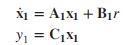
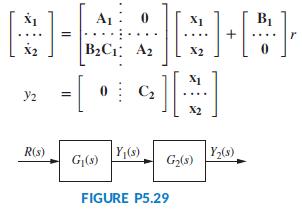
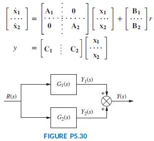
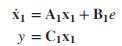
Consider the cascaded subsystems shown in Figure P5.29. If G1(s) is represented in state space asand G2(s) is represented in state space asshow that the entire system can be represented in state space as š = A1x1 + B1r Y1 = C,x1
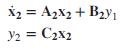
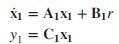
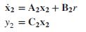
Consider the parallel subsystems shown in Figure P5.30. If G1(s) is represented in state space asand G2(s) is represented in state space as_xshow that the entire system can be represented in state space as X1 = Ajx1 + Bịr yi = C,x1 %3D
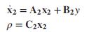
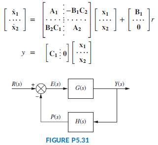
Consider the subsystems shown in Figure P5.31 and connected to form a feedback system. If G(s) is represented in state space asand H2(s) is represented in state space asshow that the closed-loop system can be represented in state space as X1 = A1X1 + B1e y = C1x1
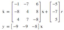
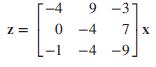
Given the system represented in state space as follows:convert the system to one where the new state vector, z, is -1 -7 6 -5 -8 4 8 x+ -7r 4 7 -8 y = [-9 -9 -8] x
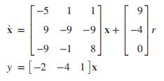
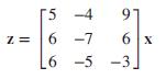
Repeat Problem 43 for the following system:and the following state-vector transformation:Data From Problem 43:Given the system represented in state space as follows:convert the system to one where the new state vector, z, is T-5 1 * = 9 -9 -9x + -4 -9 -1 8 y = [-2 -4 1]x
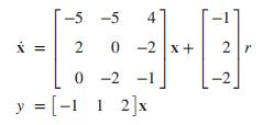
Diagonalize the following system: -5 -5 0 -2 x+ 2r 0 -2 -1 = [-1 1 1 2]x 2.
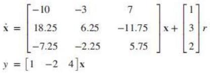
Repeat Problem 45 for the following system:Data From Problem 45:Diagonalize the following system: [-10 -3 7 X = 18.25 6.25 -11.75 x+|3 r |-7.25 -2.25 5.75 y = [1 -2 4]x %3D
Diagonalize the system in Problem 46 using MATLAB.Data From Problem 46: -10 -3 7 18.25 6.25 -11.75 x+|3 r -7.25 -2.25 5.75 y = [1 -2 4]x
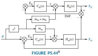
Find the closed-loop transfer function of the Unmanned Free-Swimming Submersible vehicle’s pitch control system shown on the back endpapers (Johnson, 1980).
Use Simulink to plot the effects of nonlinearities upon the closed-loop step response of the antenna azimuth position control system shown on the front endpapers, Configuration 1. In particular, consider individually each of the following nonlinearities: saturation (±5 volts), backlash (dead band
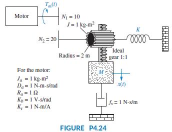
Find M and K, shown in the system of Figure P4.24, to yieldx(t) with16%overshootand20secondssettlingtime for a step input in motor torque, Tm(t). Motor N1 = 10 J= 1 kg-m? K N2 = 20 lell Ideal Radius = 2 m gear 1:1 For the motor: Ja = 1 kg-m2 Da = I N-m-s/rad Ra = 12 K = 1 V-s/rad K, = I N-m/A x(1)
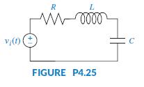
If vi(t) is a step voltage in the network shown in Figure P4.25, find the value of the resistor such that a 20% overshoot in voltage will be seen across the capacitor if C = 10-6 F and L = 1 H. R L. ell v;(1) FIGURE P4.25 +1
Given the circuit of Figure P 4.25, where C = 10 μF, find R and L to yield 15% overshoot with a settling time of 7ms for the capacitor voltage. The input, v(t), is a unit step. R L. ell v;(1) FIGURE P4.25 +1
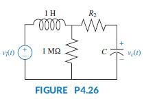
For the circuit shown in Figure P4.26, find the values of R2 and C to yield 8% overshoot with a settling time of 1 ms for the voltage across the capacitor, with vi(t) as a step input. 1H R2 lall I M2 C7 FIGURE P4.26
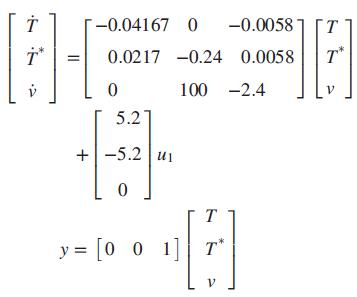
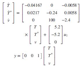
We developed a linearized state-space model of HIV infection. The model assumed that two different drugs were used to combat the spread of the HIV virus. Since this book focuses on single-input, single output systems, only one of the two drugs will be considered. We will assume that only RTIs are
Name the four components of a block diagram for a linear, time-invariant system.
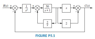
Reduce the block diagram shown in Figure P5.1 to a single transfer function, T(s) = C(s)/R(s) Use the following methods:a. Block diagram reductionb. MATLAB R(s) + 50 C(s) s+1 2 2 FIGURE P5.1
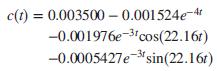
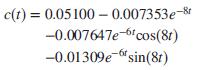
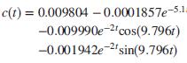
Find peak time, settling time, and percent overshoot for only those responses below that can be approximated as second-order responses.a.b.c.d. c(t) = 0.003500 – 0.001524e-4 -0.001976e-3'cos(22.16t) -0.0005427e-sin(22.16r)
For each of the following transfer functions with zeros, find the component parts of the unit step response: (1) the derivative of the response without a zero and (2) the response without a zero, scaled to the negative of the zero value. Also, find and plot the total response. Describe any
Use MATLAB’s Simulink to obtain the step response of a system,under the following conditions:a. The system is linear and driven by an amplifier whose gain is 10.b. An amplifier whose gain is 10 drives the system. The amplifier saturates at ±0.25 volts. Describe the effect of the saturation on
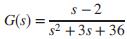
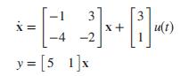
A system is represented by the state and output equations that follow. Without solving the state equation, find the poles of the system. X = -4 3. x+ -2 u(t) y = [5 1]x
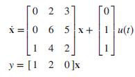
A system is represented by the state and output equations that follow. Without solving the state equation, finda. The characteristic equation;b. The poles of the system 0 2 3 i = 0 6 5x+ 1 u(t) 4 2 y = [1 2 0]x
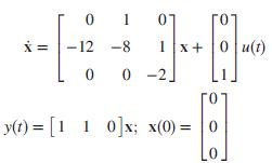
Use MATLAB to simulate the following system and plot the output, y(t), for a step input. Mark on the plot the steady-state value, percent overshoot, and the rise time, peak time, and settling time. 1 07 X = | - 12 -8 1 x+ 0 u(t) 0 -2. го y(1) = [1 1 0]x; x(0) = 0
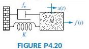
Given the translational mechanical system of Figure P4.20, where K = 1 and f(t) is a unit step, find the values of M and fv to yield a response with 17% overshoot and a settling time of 10 seconds. fr f) K FIGURE P4.20
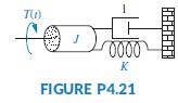
Find J and K in the rotational system shown in Figure P4.21 to yield a 30% overshoot and a settling time of 3 seconds for a step input in torque. T) K FIGURE P4.21
Given the system shown in Figure P4.22, find the damping, D, to yield a 30% overshoot in output angular displacement for a step input in torque. N1 = 25 1 kg-m? N2 =5 | N3 = 10 D. N-m/rad N4 = 5 FIGURE P4.22
For the system shown in Figure P4.23, find N1=N2 so that the settling time for a step torque input is 16 seconds. I kg-m? N1 IN-m/rad N2 I kg-m? I N-m-s/rad FIGURE P4.23
If vi(t) is a step voltage in the network shown in Figure P4.25, find the values of R and C to yield a 20% overshoot and a 1 ms settling time for vc(t) if L = 1 H. R L. ell v;(1) FIGURE P4.25 +1
Showing 500 - 600
of 942
1
2
3
4
5
6
7
8
9
10
Step by Step Answers