New Semester
Started
Get
50% OFF
Study Help!
--h --m --s
Claim Now
Question Answers
Textbooks
Find textbooks, questions and answers
Oops, something went wrong!
Change your search query and then try again
S
Books
FREE
Study Help
Expert Questions
Accounting
General Management
Mathematics
Finance
Organizational Behaviour
Law
Physics
Operating System
Management Leadership
Sociology
Programming
Marketing
Database
Computer Network
Economics
Textbooks Solutions
Accounting
Managerial Accounting
Management Leadership
Cost Accounting
Statistics
Business Law
Corporate Finance
Finance
Economics
Auditing
Tutors
Online Tutors
Find a Tutor
Hire a Tutor
Become a Tutor
AI Tutor
AI Study Planner
NEW
Sell Books
Search
Search
Sign In
Register
study help
engineering
control systems engineering
Control Systems Engineering 7th Edition Norman S. Nise - Solutions
In a system with an input and an output, what poles generate the transient response?
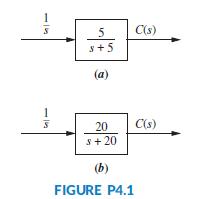
Plot the step responses for Problem 2 using MATLAB.Data From Problem 2:Find the output response, c(t), for each of the systems shown in Figure P4.1. Also find the time constant, rise time, and settling time for each case. 5 C(s) s+5 (a) 20 C(s) s+ 20 (b) FIGURE P4.1
In a system with an input and an output, what poles generate the steady-state response?
Find the output response, c(t), for each of the systems shown in Figure P4.1. Also find the time constant, rise time, and settling time for each case. 5 C(s) s+5 (a) 20 C(s) s+ 20 (b) FIGURE P4.1
What does the performance specification for a first-order system tell us?
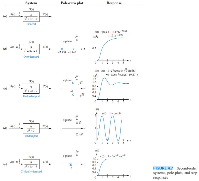
Derive the output responses for all parts of Figure 4.7. System Pole-zero plot Response G(s) R(s) = C(s) s2+ as + b General c(1) c(t) = 1 +0.17le 7854 1.0 ja 1.17leL146t G(s) S-plane R(s) =3 (b) C(s) 9 0.5 2+ 9s +9 -7.854 -1.146 Overdamped 2 3 4 5 c(1) c(1) = 1-e(cosv8r + sinv8r) =1-1.06e
A transfer function model from fluid flow to fluid temperature for a parabolic trough collector was introduced in Problem69, Chapter 2. A more detailed model for the response of this system is given under specific operation conditions (Camacho, 2012) by:Find an appropriate state-space
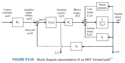
For Problem 23 in Chapter 1 we developed the functional block diagrams for the cruise control of serial, parallel, and split-powerhybrid electric vehicles (HEV). Those diagrams showed that the engine or electric motor or both may propel the vehicle. When electric motors are the sole providers of
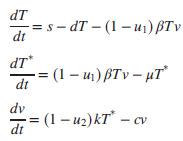
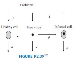
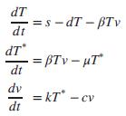
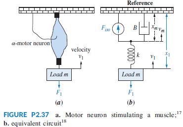
Problem 67 in Chapter 2 introduced a model for HIV infection. If retroviral drugs, RTIs and PIs as discussed in Problem22 in Chapter 1, are used, the model is modified as follows (Craig, 2004):where 0 ≤ u1 ≤ 1, 0 ≤ u2 ≤ 1 represent the effectiveness of the RTI and PI medication,
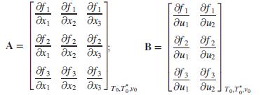
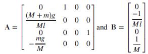
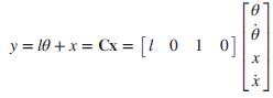
Figure P3.17 shows a free-body diagram of an inverted pendulum, mounted on a cart with a mass, M. The pendulum has a point mass, m, concentrated at the upper end of a rod with zero mass, a length, l, and a frictionless hinge. A motor drives the cart, applying a horizontal force, u(t). A gravity
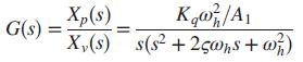
A single-pole oil cylinder valve contains a spool that regulates hydraulic pressure, which is then applied to a piston that drives a load. The transfer function relating piston displacement, Xp(s) to spool displacement from equilibrium, Xv(s), is given by (Qu, 2010):where A1 = effective area of a
Given the photovoltaic system described in Problem 65 in Chapter 2 (Agee, 2012) and defining the following state variables, system input and output as y = x1 = θm; x2 = θ̇m; x3 = ia, and u = ea, write a state-space representation of the system in the form ẋ = Ax + Bu; y = Cx.Data From Problem
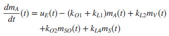
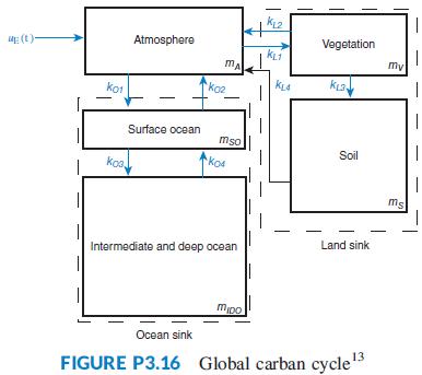
Figure P3.16 shows a schematic description of the global carbon cycle (Li, ). In the figure, mA(t) represents the amount of carbon in gigatons (GtC) present in the atmosphere of earth; mV(t) the amount in vegetation; ms(t) the amount in soil; mSO(t) the amount in surface ocean; and mIDO(t) the
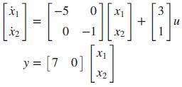
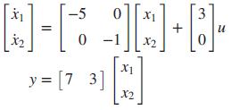
State-space representations are, in general, not unique. One system can be represented in several possible ways. For example, consider the following systems:a. ẋ = -5x + 3uy = 7xb.c.Show that these systems will result in the same transfer function. -5 X1 3 + u X2 y = [7 0] X2
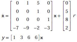
Repeat Problem 15 using MATLAB, the Symbolic Math Toolbox, and Eq.Data From Problem 15:Use MATLAB to find the transfer function, G(s)=Y(s)/R(s), for each of the following systems represented in state space:a)b) 01 Го 1 5 x+ 1 8 -9 -2 -3 2 y = [1 3 6 6]x 1.
Use MATLAB to find the transfer function, G(s)=Y(s)/R(s), for each of the following systems represented in state space:a)b) 01 Го 1 5 x+ 1 8 -9 -2 -3 2 y = [1 3 6 6]x 1.
Use MATLAB and the Symbolic Math Toolbox to find the inverse Laplace transform of the following frequency functions:a.b. (s2 + 3s + 10)(s + 5) (s + 3)(s + 4)(s2 + 2s + 100) G(s) =
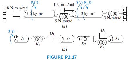
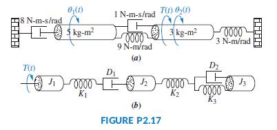
For each of the rotational mechanical systems shown in Figure P2.17, write, but do not solve, the equations of motion. 0,(1) 8 N-m-s/rad FO s kg-m? 1 N-m-s/rad T(t) 0,(1) 3 kg-m2 3 N-m/rad 9 N-m/rad (a) T(t) D2 DI J3 000 K3 KI К (b) FIGURE P2.17
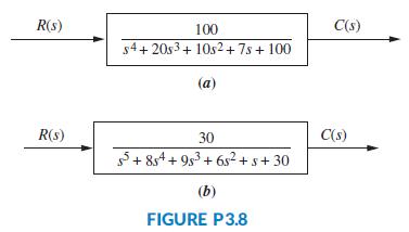
Repeat Problem 9 using MATLAB.Data From Problem 9:Find the state-space representation in phase-variable form for each of the systems shown in Figure P3.8. R(s) 100 C(s) s4+ 20s3+ 10s2+ 7s + 100 (a) R(s) 30 C(s) 5+ 8s4 + 9s3 + 6s²+ s+ 30 (b) FIGURE P3.8
State an advantage of the transfer function approach over the state-space approach.
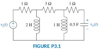
Represent the electrical network shown in Figure P3.1 in state space, where vo(t) is the output. 12 32 12 v,(1) 2 H 1H 0.5 F FIGURE P3.1
Give two reasons for modeling systems in state space.
In a significant number of cases, the open-loop transfer function from fluid flow to fluid temperature in a parabolic trough collector can be approximated (Camacho, 2012) by:a. Write an analytic expression for the unit step response of the open loop system assuming that h(t) represents the output
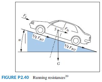
Problem 23 in Chapter 1 discusses the cruise control of serial, parallel, and split-power hybrid electric vehicles (HEVs). The functional block diagrams developed for these HEVs indicated that the speed of a vehicle depends upon the balance between the motive forces (developed by the gasoline
HIV inflicts its damage by infecting healthy CD4 + T cells (a type of white blood cell) that are necessary to fight infection. As the virus embeds in a T cell and the immune system produces more of these cells to fight the infection, the virus propagates in an opportunistic fashion. As we now
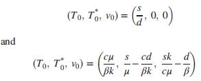
A three-phase ac/dc converter supplies dc to a battery charging system or dc motor (Graovac, 2001). Each phase has an ac filter represented by the equivalent circuit in Figure P2.38.Derive that the inductor current in terms of the two active sources is Ls V,(s) lacR(s) 1/Cs FIGURE P2.38 AC filter
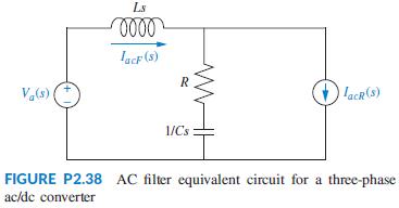
A muscle hanging from a beam is shown in Figure P2.37(a) (Lessard, 2009). The α-motor neuron can be used to electrically stimulate the muscle to contract and pull the mass, m, which under static conditions causes the muscle to stretch. An equivalent mechanical system to this setup is shown in
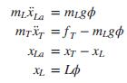
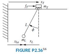
Figure P2.36 shows a crane hoisting a load. Although the actual system’s model is highly nonlinear, if the rope is considered to be stiff with a fixed length L, the system can be modeled using the following equations:where mL is the mass of the load, mT is the mass of the cart, xT and xL are
What do we call the mechanical equations written in order to evaluate the transfer function?
Why do transfer functions for mechanical networks look identical to transfer functions for electrical networks?
The motor’s transfer function relates armature displacement to armature voltage. How can the transfer function that relates load displacement and armature voltage be determined?
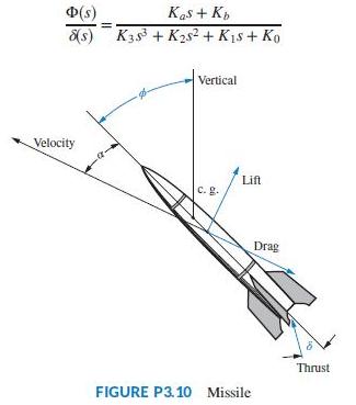
A missile in flight, as shown in Figure P3.10, is subject to four forces: thrust, lift, drag, and gravity. The missile flies at an angle of attack, α, from its longitudinal axis, creating lift. For steering, the body angle from vertical, ϕ, is controlled by rotating the engine at the tail. The
Experiments to identify precision grip dynamics between the index finger and thumb have been performed using a ball-drop experiment. A subject holds a device with a small receptacle into which an object is dropped, and the response is measured (Fagergren, 2000). Assuming a step input, it has been
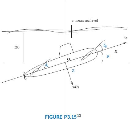
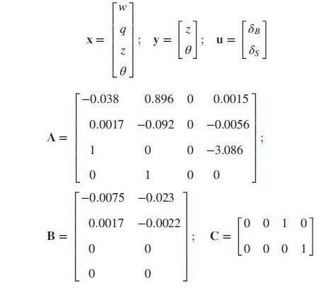
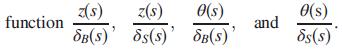
In this chapter, we described the state-space representation of single input, single-output systems. In general, systems can have multiple inputs and multiple outputs. An autopilot is to be designed for a submarine as shown in Figure P3.15 to maintain a constant depth under severe wave
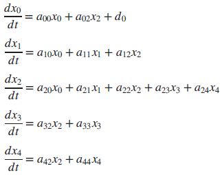
A linear, time-invariant model of the hypothalamic pituitary-adrenal axis of the endocrine system with five state variables has been proposed as follows (Kyrylov, 2005):where each of the state variables represents circulatory concentrations as follows:x0 = corticotropin-releasing hormonex1 =
In the past, Type-1 diabetes patients had to inject themselves with insulin three to four times a day. New delayed-action insulin analogues such as insulin Glargine require a single daily dose. A similar procedure to the one described in the Pharmaceutical Drug Absorption case study of this chapter
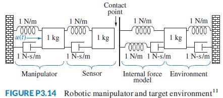
Modern robotic manipulators that act directly upon their target environments must be controlled so that impact forces as well as steady-state forces do not damage the targets. At the same time, the manipulator must provide sufficient force to perform the task. In order to develop a control system
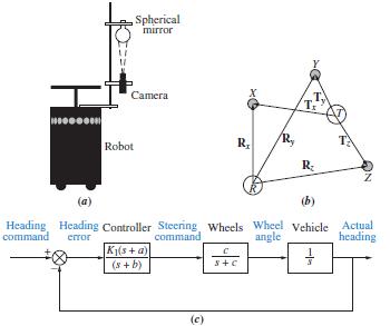
Image-based homing for robots can be implemented by generating heading command inputs to a steering system based on the following guidance algorithm. Suppose the robot shown in Figure P3.13(a) is to go from point R to a target, point T, as shown in Figure P3.13(b). If Rx, Ry, and Rz are vectors
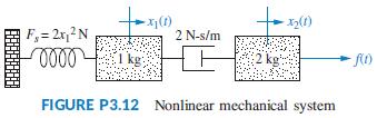
Consider the mechanical system of Figure P3.12. If the spring is nonlinear, and the force, Fs, required to stretch the spring is Fs = 2x21 , represent the systemin state space linearized about x1 = 1 if the output is x2. F,= 2r,2N 2 N-s/m 1 kg: 2 kg FIGURE P3.12 Nonlinear mechanical system
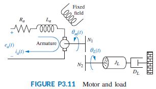
Given the dc servomotor and load shown in Figure P3.11, represent the system in state space, where the state variables are the armature current, ia, load displacement, θL, and load angular velocity,ωL. Assume that the output is the angular displacement of the armature. Do not neglect armature
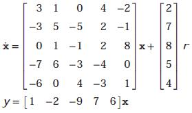
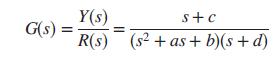
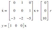
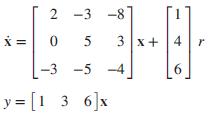
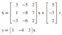
Find the transfer function G(s) = Y(s)=R(s) for each of the following systems represented in state space:a)b)c) 07 0 0 1x+ -3 -2 -5 10 y = [1 0 0]x
What is meant by the phase-variable form of the state equation?
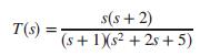
Represent the following transfer function in state space. Give your answer in vector-matrix form. s(s + 2) T(s) (s+ 1Xs² + 2s + 5)
If an electrical network has three energy-storage elements, is it possible to have a state-space representation with more than three state variables? Explain.
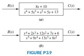
Repeat Problem 11 using MATLAB.Data From Problem 11:For each system shown in Figure P3.9, write the state equations and the output equation for the phase-variable representation. R(s) 8s + 10 C(s) s4 + 5s + s2 + 5s + 13 (a) R(s) C(s) s4+ 2s3+ 12s2+ 7s +6 55+ 9s4+ 13s3+ 852 (b) FIGURE P3.9
What is a convenient choice of state variables for electrical networks?
For each system shown in Figure P3.9, write the state equations and the output equation for the phase-variable representation. R(s) 8s + 10 C(s) s4 + 5s + s2 + 5s + 13 (a) R(s) C(s) s4+ 2s3+ 12s2+ 7s +6 55+ 9s4+ 13s3+ 852 (b) FIGURE P3.9
What factors influence the choice of state variables in any system?
What is meant by linear independence?
Find the state-space representation in phase-variable form for each of the systems shown in Figure P3.8. R(s) 100 C(s) s4+ 20s3+ 10s2+ 7s + 100 (a) R(s) 30 C(s) 5+ 8s4 + 9s3 + 6s²+ s+ 30 (b) FIGURE P3.8
If the state equations are a system of first-order differential equations whose solution yields the state variables, then the output equation performs what function?
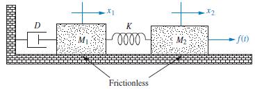
Show that the system of Figure 3.7 in the text yields a fourth-order transfer function if we relate the displacement of either mass to the applied force, and a third-order one if we relate the velocity of either mass to the applied force.Figure 3.7: D K M2 Frictionless
An eighth-order system would be represented in state space with how many state equations?
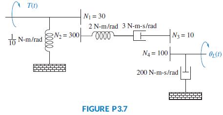
Represent the system shown in Figure P3.7 in state space where the output is θL(t). T() N1 = 30 2 N-m/rad 3 N-m-s/rad TO N-m/rad N2 = 3000000 N3 = 10 fam N4 = 100 200 N-m-s/rad FIGURE P3.7
What is required to represent a system in state space?
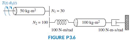
Represent the rotational mechanical system shown in Figure P3.6 in state space, where θ1(t) is the output. T(t) 0,(1) 50 kg-m2 N1 = 30 N2 = 10000000 100 kg-m? HE 100 N-m/rad 100 N-m-s/rad FIGURE P3.6
Define state space.
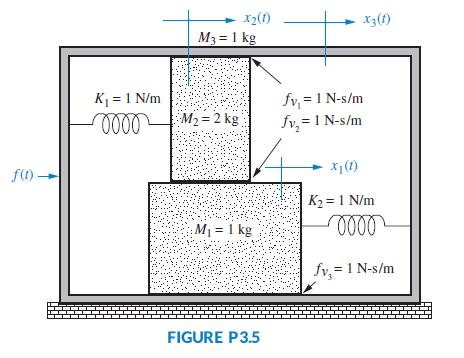
Represent the translational mechanical system shown in Figure P3.5 in state space, where x1(t) is the output. x2(1) M3 = 1 kg x3(1) K = 1 N/m fv, = 1 N-s/m M2 = 2 kg fv, = 1 N-s/m f(1). X1(1) K2 = 1 N/m M = 1 kg fv, = 1 N-s/m FIGURE P3.5
Define state vector.
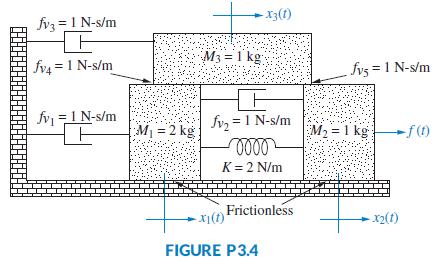
Represent the system shown in Figure P3.4 in state space where the output is x3(t). X3(t) fvz = 1 N-s/m M3 = 1 kg %3D fv4 = 1 N-s/m fvs = 1 N-s/m fv =1 N-s/m fvz = 1 N-s/m M1 = 2 kg M2 = 1 kg f() K= 2 N/m Frictionless -x2(1) FIGURE P3.4
Define state.
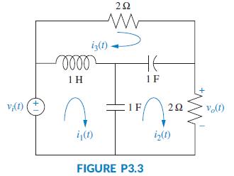
Find the state-space representation of the network shown in Figure P3.3 if the output is vo(t). iz(1). 1 H 1F v,(1) 1 F 22 i(1) iz(1) FIGURE P3.3
Define state variables.
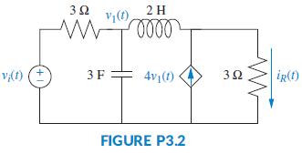
Represent the electrical network shown in Figure P3.2 in state space, where iR(t) is the output. 3Ω 2H Vy(1) v(t) 3F 4v1(1) 32 iR(1) FIGURE P3.2
In order to design an underwater vehicle that has the characteristics of both a long-range transit vehicle (torpedo-like) and a highly maneuverable low-speed vehicle (boxlike), researchers have developed a thruster that mimics that of squid jet locomotion (Krieg, 2008). It has been demonstrated
In a paint mixing plant, two tanks supply fluids to a mixing cistern. The height, h, of the fluid in the cistern is dependent upon the difference between the input mass flow rate, q, and the output flow rate, qe. A nonlinear differential equation describing this dependency is given by (Schiop,
The Gompertz growth model is commonly used to model tumor cell growth. Let v(t) be the tumor’s volume, thenwhere λ and α are two appropriate constants (Edelstein- Keshet, 2005).a. Verify that the solution to this equation is given by v(t) = v0eλ/α(1 -e-αt), where v0 is the initial tumor
A photovoltaic system is used to capture solar energy to be converted to electrical energy. A control system is used to pivot the solar platform to track the sun’s movements in order to maximize the captured energy. The system consists of a motor and load similar to that discussed in Section 2.8.
If we understand the form the mechanical equations take, what step do we avoid in evaluating the transfer function?
Use MATLAB and the Symbolic Math Toolbox to find the Laplace transform of the following time functions:a. f (t) = 8t2cos (3t + 45°)b. f (t) = 3te-2tsin (4t + 60°)
What function do gears perform?
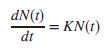
In 1978, Malthus developed a model for human growth population that is also commonly used to model bacterial growth as follows. Let N(t) be the population density observed at time t. Let K be the rate of reproduction per unit time. Neglecting population deaths, the population density at a time t +
For each of the following transfer functions, write the corresponding differential equation.a.b.c. X(s) 7 F(s) s2 + 5s + 10
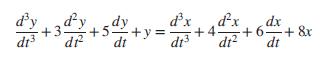
A system is described by the following differential equation:Find the expression for the transfer function of the system, Y(s) = X(s). d'y dy d'x di dx +6=+ &x dt? dx +3 dr dr +5 +y +4. dt dt
What are the component parts of the mechanical constants of a motor’s transfer function?
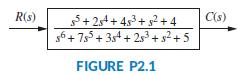
Write the differential equation for the system shown in Figure P2.1. R(s) 5+ 24+ 453+ 32 + 4 C(s) g6+ 75 + 35 + 25 + s²+5 FIGURE P2.1
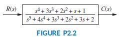
Write the differential equation that is mathematically equivalent to the block diagram shown in Figure P2.2. Assume that r(t) = 3t3. R(s) C(s) 4+ 353+ 252 +s+1 5+ 4s4 + 3s3 + 2s2 + 3s+ 2 FIGURE P2.2
Summarize the steps taken to linearize a nonlinear system.
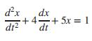
A system is described by the following differential equation:with the initial conditions x(0) = 1; x: (0) = -1. Show a block diagram of the system, giving its transfer function and all pertinent inputs and outputs. dx dx +4 +5x = 1 dt dt?
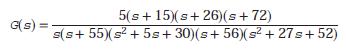
Use MATLAB to generate the transfer function:in the following ways:a. The ratio of factors;b. The ratio of polynomials. 5(s+ 15)(s+ 26)(s+ 72) G(s) = s(s+ 55)(s + 5s+ 30)(s+ 56)(s? + 27s+ 52)
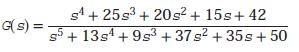
Repeat Problem 13 for the following transfer function:Data from Problem 13:Use MATLAB to generate the transfer function:in the following ways:a. The ratio of factors;b. The ratio of polynomials. G(s) = s4 + 25s3 + 20s? + 15s+ 42 s5 + 13s4 + 9s3 + 37s2 + 35s+ 50
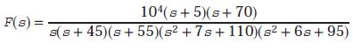
Use MATLAB to generate the partialfraction expansion of the following function: 104(s+ 5)(s+70) s(s+ 45)(s+ 55)(s² + 7s+110)(s² + 6s+ 95) F(s) =
Use MATLAB and the Symbolic Math Toolbox to input and form LTI objects in polynomial and factored form for the following frequency functions:a.b. 45(s? + 37s+ 74)(s + 28s? + 32s + 16) (s+ 39)(s+ 47)(s? + 2s+ 100)(s + 27s? + 18s+ 15) Gs) %3D
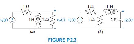
Find the transfer function, G(s) = Vo(s)/Vi (s), for each network shown in Figure P2.3. 12 12 1 H 22 Vo(f) vi(t) e 2F木Vo() vi(t) 1H 10 (a) (b) FIGURE P2.3
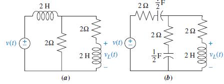
Find the transfer function, G(s) = VL(s)/V(s), for each network shown in Figure P2.4. 2H 20 F 22 22 v(t) ( 20 + v(1) 2H3 2 H (a) (b) 1/2 ++ +1
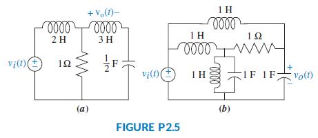
Find the transfer function, G(s) = Vo(s)/Vi(s), for each network shown in Figure P2.5. Solve the problem using mesh analysis. + V(1)- 1 H 1 H 10 2 H 3 H vi(1) 12 vi(1) 1F Volt) (a) (b) FIGURE P2.5 HE 1/2
Repeat Problem 19 using nodal equations.Data From Problem 19:Find the transfer function, G(s) = Vo(s)/Vi(s), for each network shown in Figure P2.5. Solve the problem using mesh analysis. + V(1)- 1 H 1 H 10 2 H 3 H vi(1) 12 vi(1) 1F Volt) (a) (b) FIGURE P2.5 HE 1/2
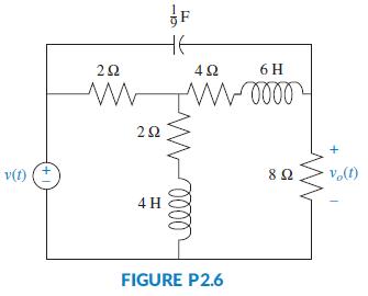
a. Write, but do not solve, the mesh and nodal equations for the network of Figure P2.6.b. Use MATLAB, the Symbolic Math Toolbox, and the equations found in part a to solve for the transfer function, G(s) = Vo(s)/V(s). Use both the mesh and nodal equations and show that either set yields the same
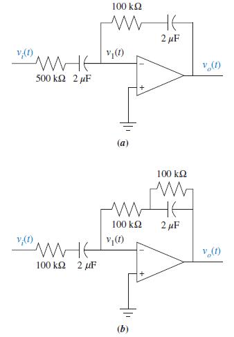
Find the transfer function, G(s) = Vo(s)/Vi(s), for each operational amplifier circuit shown in Figure P2.7. 100 kQ 2 µF の 500 k2 2 µF 100 k2 100 k2 2 µF の (1)'a 100 k2 2 uF (b)
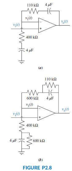
Find the transfer function, G(s) = Vo(s)/Vi(s), for each operational amplifier circuit shown in Figure P2.8. 110 k2 4 µF の (1ya 400 k2 4 µF (a) 110 k2 HE 600 k2 4 µF 400 k2 4 µF 600 k2 (b) FIGURE P2.8 WHE
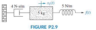
Find the transfer function, G(s) = X1(s)/F(s), for the translational mechanical system shown in Figure P2.9. -x(1) 4 N-s/m 5 N/m 5 kg FIGURE P2.9
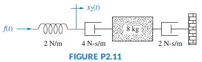
Find the transfer function, G(s) = X2(s)/F(s), for the translational mechanical system shown in Figure P2.11. 8 kg 2 N/m 4 N-s/m 2 N-s/m FIGURE P2.11
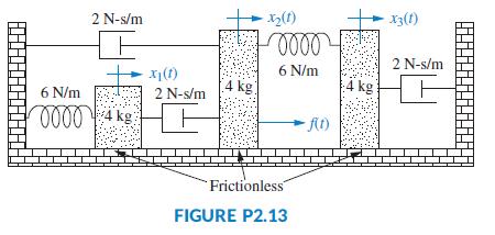
Find the transfer function, G(s) = X3(s)/F(s), for the translational mechanical system shown in Figure P2.13. 2 N-s/m x3(1) 2 N-s/m x(1) 6 N/m 4 kg 4 kg 6 N/m 2 N-s/m 0000 4 kg Frictionless FIGURE P2.13
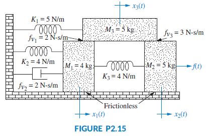
Write, but do not solve, the equations of motion for the translational mechanical system shown in Figure P2.15. x3(1) K = 5 N/m M3 = 5 kg: fvz = 3 N-s/m fv, = 2 N-s/m- K2 = 4 N/m ML=4 kg: 0000M2 = 5 kg t) K3 = 4 N/m fy, = 2 N-s/m Frictionless x(t) X2(t) FIGURE P2.15
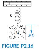
For the unexcited (no external force applied) system of Figure P2.16, do the following:a. Write the differential equation that describes the system.b. Assuming initial conditions x(0) = x0 and ẋ(0) = x1, write a Laplace transform expression for X(s).c. Find x(t) by obtaining the inverse Laplace
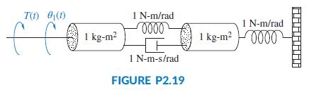
Find the transfer function, θ1(s)/T(s) , for the system shown in Figure P2.19. T(1) 0(1) 1 N-m/rad 1 N-m/rad 1 kg-m? 0000 1 kg-m? 1 N-m-s/rad FIGURE P2.19
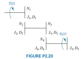
For the rotational mechanical system with gears shown in FigureP2.20,findthe transfer function, G(s) = θ3(s)/T(s). The gears have inertia and bearing friction as shown. T(t) to J1. D N2 N3 Jz, D2 J3, Dz 0,(0) N4 J4. D4 J5, D5 FIGURE P2.20
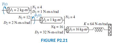
For the rotational system shown in Figure P2.21, find the transfer function, G(s) = θ2(s)=T(s). |N = 4 F = 2 kg-mHD =I N-m-s/rad N2 = 12in0 D2 = 2 N-m-s/rad 6,() 2 = 1 kg-m-=* K= 64 N-m/rad N4 = 16 D3 = 32 N-m-s/rad s = 16 kg-m000 FIGURE P2.21
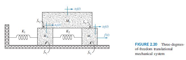
Find the series and parallel analogs for the translational mechanical system shown in Figure 2.20 in the text.Figure 2.20: - 13(1) () K1 K2 FIGURE 2.20 Three-degrees- of-freedom translational mechanical system
Find the series and parallel analogs for the rotational mechanical systems shown in Figure P2.17(b) in the problems.Figure P2.17(b): I N-m-s/rad T(1) 0,(1) 18 N-m-s/rad E C kg-m? 3 kg-m? 3 N-m/rad 9 N-m/rad (a) TO) D2 DI KI K2 (b) FIGURE P2.17
Showing 700 - 800
of 942
1
2
3
4
5
6
7
8
9
10
Step by Step Answers