New Semester
Started
Get
50% OFF
Study Help!
--h --m --s
Claim Now
Question Answers
Textbooks
Find textbooks, questions and answers
Oops, something went wrong!
Change your search query and then try again
S
Books
FREE
Study Help
Expert Questions
Accounting
General Management
Mathematics
Finance
Organizational Behaviour
Law
Physics
Operating System
Management Leadership
Sociology
Programming
Marketing
Database
Computer Network
Economics
Textbooks Solutions
Accounting
Managerial Accounting
Management Leadership
Cost Accounting
Statistics
Business Law
Corporate Finance
Finance
Economics
Auditing
Tutors
Online Tutors
Find a Tutor
Hire a Tutor
Become a Tutor
AI Tutor
AI Study Planner
NEW
Sell Books
Search
Search
Sign In
Register
study help
engineering
control systems engineering
Control Systems Engineering 7th Edition Norman S. Nise - Solutions
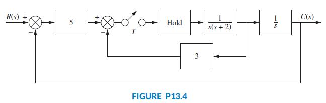
Find the closed-loop transfer function, T(z) = C(z)/R(z), for the system shown in Figure P13.4. R(s) + C(s) 5 Hold s(s + 2) T 3 FIGURE P13.4
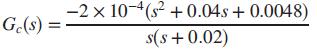
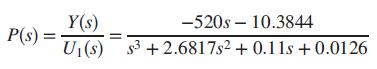
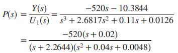
In Chapter 11, a continuous cascaded compensator for a unity feedback system was designed for the treatment of the HIV-infected patient treated with RTIs (Craig, 2004). The transfer function of the designed compensator wasThe linearized plant was given byThe compensated system is overdamped with an
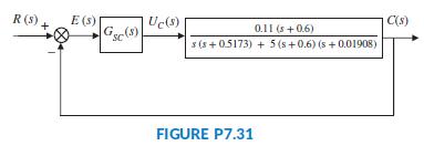
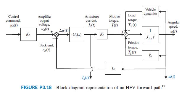
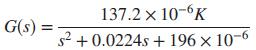
In Problem 67, Chapter 7 (Figure P7.31), the block diagram of a cascade scheme for the speed control of an HEV (Preitl, 2007) was represented as a unity feedback system. In that diagram the output of the system is the speed transducer’s output voltage, C(s) = KssV(s). In Part b of Problem 33,
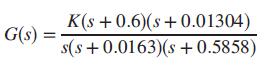
In Problem34, Chapter 11, a zero steady-state error for a unit-step input was achieved through the design of a lag compensator with integral control. In that problem, the open-loop transmission can be written as L(s) = Gc(s)G(s), where the parabolic trough plant is given by (Camacho, 2012)and the
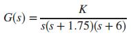
Given a unity feedback system withdesign a PID controller to yield zero steady-state error for a ramp input, as well as a 20% overshoot, and a peak time less than 1.8 seconds for a step input. Use only frequency response methods. K G(s) : s(s + 1.75)(s +6)
A unity feedback system hasIf this system has an associated 0.5 second delay, use MATLAB to design the value of K for 20% overshoot. Make any necessary second-order approximations, but test your assumptions by simulating your design. The delay can be represented by cascading the MATLAB function
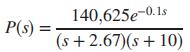
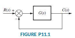
The model for a specific linearized TCP/IP computer network queue, working under a random early detection (RED) algorithm, has been modeled using the block diagram of Figure P11.1, where G(s) = M(s)P(s), withandAlso, L is a parameter to be varied (Hollot, 2001).a. Adjust L to obtain a 15% overshoot
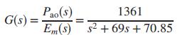
An electric ventricular assist device (EVAD) that helps pump blood concurrently to a defective natural heart in sick patients can be shown to have a transfer functionThe input, Em(s), is the motor’s armature voltage, and the output is Pao(s), the aortic blood pressure (Tasch, 1990). The EVAD will
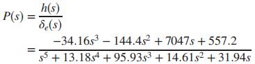
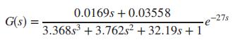
A Tower Trainer 60 Unmanned Aerial Vehicle has a transfer functionwhere δe(s) is the elevator angle and h(s) is the change in altitude (Barkana, 2005).a. Assuming the airplane is controlled in the closed loop configuration of Figure P11.1 with G(s) = KP(s), find the value of K that will result in
The transfer function from applied force to arm displacement for the arm of a hard disk drive has been identified as The position of the arm will be controlled using the feedback loop shown in Figure P11.1 (Yan, 2003). a. Design a lead compensator to achieve closed-loop stability with a
For the heat exchange system described in Problem 39, Chapter 9 (Smith, 2002):a. Design a passive lag-lead compensator to achieve 5% steady-state error with a transient response of 10% overshoot and a settling time of 60 seconds for step inputs.b. Use MATLAB to simulate and verify your design.
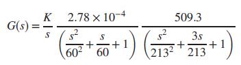
Active front steering is used in front-steering four wheel cars to control the yaw rate of the vehicle as a function of changes in wheel-steering commands. For a certain car, and under certain conditions, it has been shown that the transfer function from steering wheel angle to yaw rate is given by
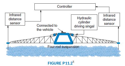
Figure P11.2 illustrates a set of booms used for the delivery of chemicals in agriculture (Sun, 2011). Each of the booms has equally spaced nozzles, the purpose of which is to maintain a constant gap between the nozzles and the soil despite car movements due to road unevenness. The booms are
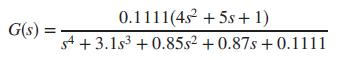
The amount of leftover moisture in a grain drying conveyor process can be controlled by varying the conveyor’s motor speed (Mansor, 2011). Although the process is highly variable, the transfer function at one of the operating points has been found to beA unity feedback system will be built around
Problem 52 in Chapter 10 mentioned a measurement based technique to design fixed-structure controllers, which does not require system identification. In that problem, we assumed a plant transfer function of (Khadraoui, 2013)Again, the interested reader is directed to the reference for further
In Chapter 6, the model for an HIV/AIDS patient treated with RTIs was linearized and shown to beIt is assumed here that the patient will be treated and monitored using the closed-loop configuration shown in Figure P11.1 Since the plant has a negative dc gain, assume for simplicity that G(s) = Gc(s)
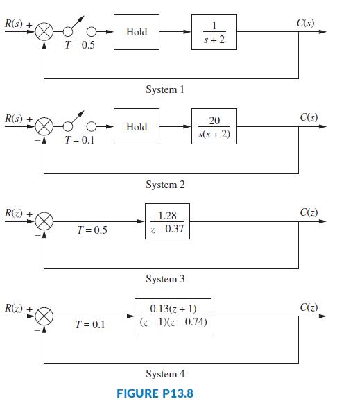
Use Simulink to simulate the step response for the system of Problem 17. Set the value of gain, K, to that designed in Problem 17 for 15% overshoot.Data from Problem 17For the digital system shown in Figure P13.5, where G1(s) = K/[(s + 1)(s + 5)], find the value of K to yield a 15% overshoot. Also
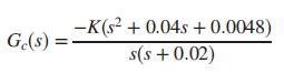
Use MATLAB’s LTI Viewer to deter mine the peak time and settling time of the closed-loop step response for System 4 in Figure P13.8. R(s) + C(s) Hold s+2 T= 0.5 System 1 R(s) + 20 C(s) Hold s(s + 2) T= 0.1 System 2 R(z) + 1.28 C(2) T=0.5 z- 0.37 System 3 R(z) + 0.13(z + 1) C(z) T= 0.1 (z - 1)(z
Describe how digital compensators can be designed on the s-plane.
Write a MATLAB program that can be used to design the gain of a digital control system to meet a percent overshoot requirement. The program will be used for systems of the type represented in Figure P13.5 and meet the following requirements:a. The user will input the desired percent overshoot.b.
What characteristic is common between a cascade compensator designed on the s-plane and the digital compensator to which it is converted?
For the digital system shown in Figure P13.5, where G1(s) = K/[s(s + 1)], find the value of K to yield a peak time of 2 seconds if the sampling interval, T, is 0.2 second. Also, find the range of K for stability.
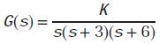
For the digital system shown in Figure P13.5, where G1(s) = K/[s(s + 1((s + 3)], find the value of K to yield a 20% overshoot if the sampling interval, T, is 0.1 second. Also, find the range of K for stability.
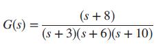
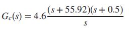
A PID controller was designed in Example 9.5 for a continuous system with unity feedback. The system’s plant wasThe designed PID controller wasFind the digital transfer function, Gc(z), of the PID controller in order for the system to be computer controlled if the sampling interval, T, is 0.005
A continuous unity feedback system has a forward transfer function ofThe system is to be computer controlled with the following specifications: Percent overshoot: 10% Settling time: 2 seconds Sampling interval: 0:01 second Design a lead compensator for the digital system to
a. Convert the heading control for the UFSS vehicle shown on the back endpapers (Johnson, 1980) into a digitally controlled system.b. Find the closed-loop pulse transfer function, T(z), if T = 0.1 second.c. Find the range of heading gain to keep the digital system stable.
In Part b of Problem 54 in Chapter 10, we used a proportional-plus-integral (PI) speed controller that resulted in an overshoot of 20% and a settling time, Ts = 3:92 seconds (Preitl, 2007). a. Now assume that the system specifications require a steady-state error of zero for a step input, a
In order to reduce the steady-state error of the parabolic trough collector system, a PI controller is added to the open-loop transfer function so that (Camacho, 2012)a. Draw the new resulting Nyquist diagram when K = 1.b. Find the range of K for closed-loop stability.c. Use a phase margin argument
Briefly describe an advantage that state-space techniques have over root locus techniques in the placement of closed-loop poles for transient response design.
Consider the following open-loop transfer functions, where G(s) = Y(s)/U(s). Y(s) is the Laplace transform of the output, and U(s) is the Laplace transform of the input control signal:i.ii.iii.iv.v.For each of these transfer functions, do the following:a. Draw the signal-flow graph in
Briefly describe the design procedure for a controller.
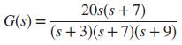
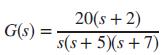
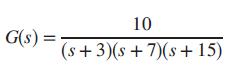
The following open-loop transfer functions can be represented by signal-flow graphs in cascade form.i.ii.For each, do the following:a. Draw the signal-flowgraph and show the state-variable feedback.b. Find the closed-loop transfer function with state variable feedback. 30(s + 2)(s + 7) G(s) =
Different signal-flow graphs can represent the same system. Which form facilitates the calculation of the variable gains during controller design?
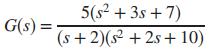
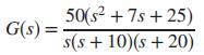
The following open-loop transfer functions can be represented by signal-flow graphs in parallel form.i.ii.For each, do the following:a. Draw the signal-flowgraph and show the state-variable feedback.b. Find the closed-loop transfer function with state variable feedback. 50(s? + 7s + 25) s(s + 10)(s
In order to effect a complete controller design, a system must be controllable. Describe the physical meaning of controllability.
Given the following open-loop plant, design a controller to yield a 10% overshoot and a settling time of 0.5 second. Place the third pole 10 times as far from the imaginary axis as the dominant pole pair. Use the phase variables for state-variable feedback. 50 G(s) (s + 1)(s + 3)(s + 10)
Under what conditions can inspection of the signal-flow graph of a system yield immediate determination of controllability?
Section 12.2 showed that controller design is easier to implement if the uncompensated system is represented in phase-variable form with its typical lower companion matrix. We alluded to the fact that the design can just as easily progress using the controller canonical form with its upper
In order to determine controllability mathematically, the controllability matrix is formed, and its rank evaluated. What is the final step in determining controllability if the controllability matrix is a square matrix?
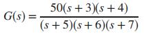
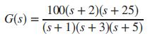
Given the following open-loop plant: design a controller to yield 10% overshoot with a peak time of 0.5 second. Use the controller canonical form for state-variable feedback. 100(s + 2)(s + 25) G(s) = (s + 1)(s + 3)(s +5)
What is an observer?
Given the following open-loop plant:design a controller to yield a10%overshoot and a settling time of 2 seconds. Place the third pole 10 times as far from the imaginary axis as the dominant pole pair. Use the phase variables for state-variable feedback. 20(s + 2) s(s+ 5)(s + 7) G(s) =
Under what conditions would you use an observer in your state-space design of a control system?
Repeat Problem 4 assuming that the plant is represented in the cascade form. Do not convert to phase-variable form.Data from Problem 4Given the following open-loop plant, design a controller to yield a 10% overshoot and a settling time of 0.5 second. Place the third pole 10 times as far from
Briefly describe the configuration of an observer.
Repeat Problem 7 assuming that the plant is represented in the parallel form. Do not convert to phase-variable form.Data from Problem 7Given the following open-loop plant:design a controller to yield a10%overshoot and a settling time of 2 seconds. Place the third pole 10 times as far from the
What plant representation lends itself to easier design of an observer?
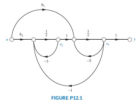
a. Given the plant shown in Figure P12.1, what relationship exists between b1 and b2 to make the system uncontrollable?b. What values of b2 will make the system uncontrollable if b1 = 1? bị b2 -O y X2 -3 -1 FIGURE P12.1
Briefly describe the design technique for an observer, given the configuration you described in Question 9.
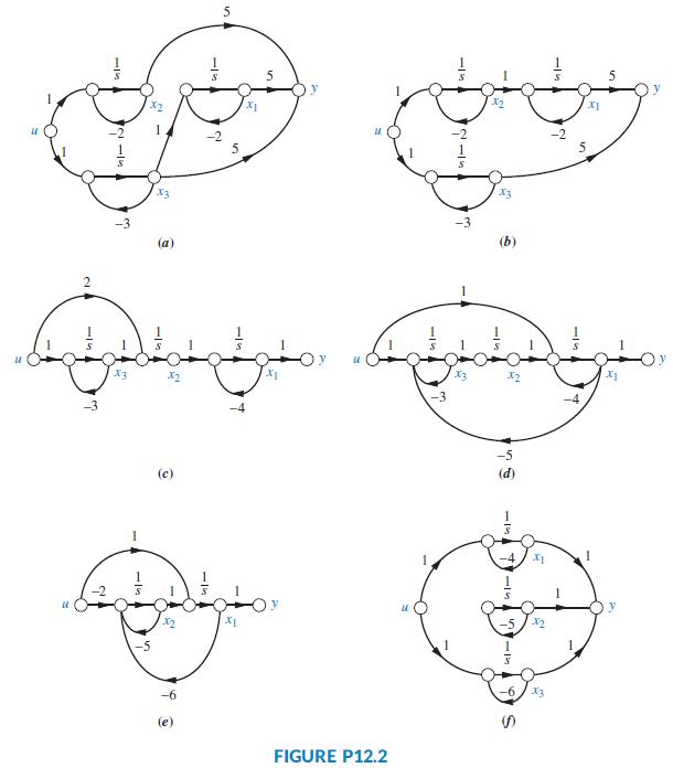
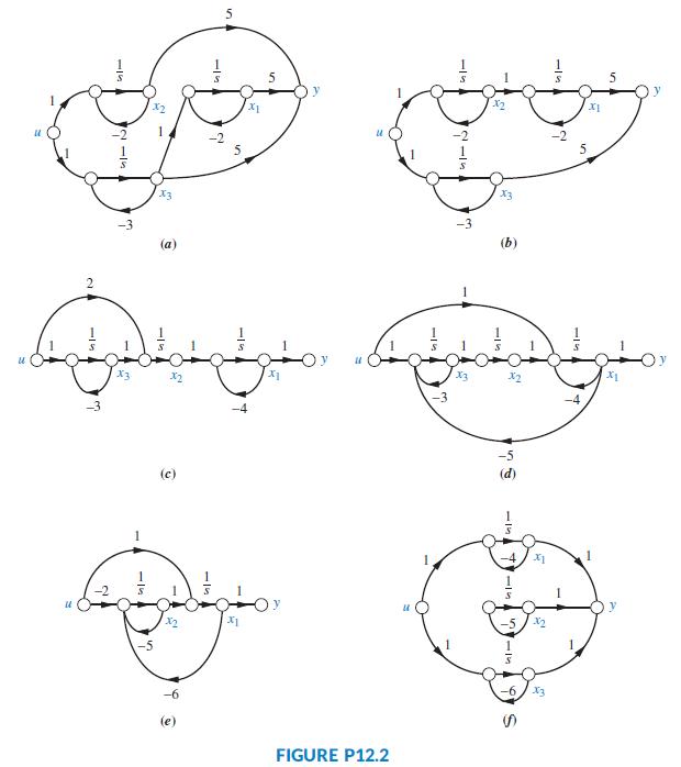
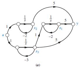
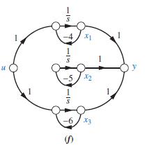
For each of the plants represented by signal-flow graphs in Figure P12.2, determine the controllability. If the controllability can be determined by inspection, state that it can and then verify your conclusions using the controllability matrix. X2 1. -2 5 X3 (a) X2 (c) -> FIGURE P12.2 2.
Compare the major difference in the transient response of an observer to that of a controller. Why does this difference exist?
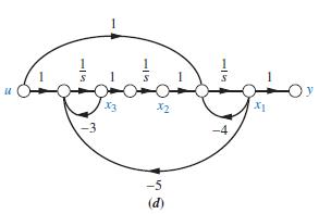
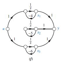
Use MATLAB to determine the controllability of the systems of Figure P12.2(d) and (f).Data from Figure 12.2 X3
From what equation do we find the characteristic equation of the controller compensated system?
In Section 12.4, we discussed how to design a controller for systems not represented in phase-variable form with its typical lower companion matrix. We described how to convert the system to phase-variable form, design the controller, and convert back to the original representation. This technique
From what equation do we find the characteristic equation of the observer?
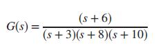
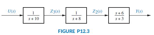
Consider the following transfer function: If the system is represented in cascade form, as shown in Figure P12.3, design a controller to yield a closed loop response of 10% overshoot with a settling time of 1 second. Design the controller by first transforming the plant to phase variables. (s
In order to effect a complete observer design, a system must be observable. Describe the physical meaning of observability.
Use MATLAB to design the controller gains for the system given in Problem 14.Data from Problem 14Consider the following transfer function: If the system is represented in cascade form, as shown in Figure P12.3, design a controller to yield a closed loop response of 10% overshoot with a
Repeat Problem 14 assuming that the plant is represented in parallel form.Data from problem 14Consider the following transfer function: If the system is represented in cascade form, as shown in Figure P12.3, design a controller to yield a closed loop response of 10% overshoot with a settling
In order to determine observability mathematically, the observability matrix is formed and its rank evaluated. What is the final step in determining observability if the observability matrix is a square matrix?
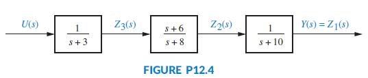
The open-loop system of Problem 14 is represented as shown in Figure P12.4. If the output of each block is assigned to be a state variable, design the controller gains for feedback from these state variables. U(s) Z3(s) Z2(s) Y(s) = Z1(s) S+6 S+3 S+8 S+ 10 FIGURE P12.4
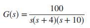
If an open-loop plant is represented in parallel form, design a controller to yield a closed-loop response of 20% overshoot and a peak time of 0.2 second. Design the controller by first transforming the plant to controller canonical form. 100 G(s) = s(s + 4)(s+ 10)
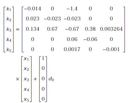
For a specific individual, the linear time-invariant model of the hypothalamic-pituitary adrenal axis of the endocrine system with five state variables has been found to be (Kyrylov, 2005)The state-variable definitions were given in Problem 23, Chapter 3.a. Use MATLAB to determine if the system is
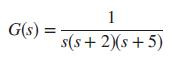
Consider the plant whose state variables are not available. Design an observer for the observer canonical variables to yield a transient response described by ζ = 0.6 and ωn = 50. Place the third pole 10 times farther from the imaginary axis than the dominant poles. 1 G(s) = s(s+ 2)(s+ 5)
Design an observer for the plant operating with 10% overshoot and 2 seconds peak time. Design the observer to respond 10 times as fast as the plant. Place the observer third pole 20 times as far from the imaginary axis as the observer dominant poles. Assume the plant is represented in observer
Repeat Problem20 assuming that the plant is represented in phase-variable form. Do not convert to observer canonical form.Data from Problem 20Consider the plant whose state variables are not available. Design an observer for the observer canonical variables to yield a transient response
Consider the plant whose phase variables are not available. Design an observer for the phase variables with a transient response described by ζ = 0.6 and ωn = 120. Do not convert to observer canonical form. (s + 2) G(s : (s + 5)(s+9)
Determine whether or not each of the systems shown in Figure P12.2 is observable. -2 -3 (a) X3 (c) FIGURE P12.2 2.
Use MATLAB to determine the observability of the systems of Figure P12.2 (a) and (f).Data from Figure 12.2 X1 -2 X3 -3 (a)
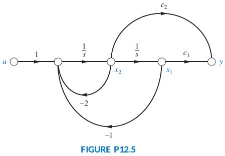
a. Given the plant of Figure P12.5, what relationship must exist between c1 and c2 in order for the system to be unobservable?b. What values of c1 will make the system uncontrollable if c2 = 1? C2 1 y X2 -2 -1 FIGURE P12.5 15
Use MATLAB to design the observer gains for the system given in Problem 27.Data from Problem 27Design an observer for the plant represented in cascade form. Transform the plant to observer canonical form for the design. Then transform the design back to cascade form. The characteristic
Repeat Problem 27 assuming that the plant is represented in parallel form.Data from Problem 27Design an observer for the plant represented in cascade form. Transform the plant to observer canonical form for the design. Then transform the design back to cascade form. The characteristic
Design an observer forrepresented in phase-variable form with a desired performance of 10% overshoot and a settling time of 0.5 second. The observer will be 10 times as fast as the plant, and the observer’s nondominant pole will be 10 times as far from the imaginary axis as the observer’s
Observability and controllability properties depend on the state-space representation chosen for a given system. In general, observability and controllability are affected when pole-zero cancellations are present in the transfer function. Consider the following two systems with representations:a.
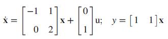
Given the plant design an integral controller to yield a 15% overshoot, 0.6-second settling time, and zero steady-state error for a step input. -1 1] u; y= [1 1]x X+ 0 2
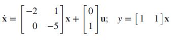
Repeat Problem 32 for the following plant: Data from Problem 32Given the plant design an integral controller to yield a 15% overshoot, 0.6-second settling time, and zero steady-state error for a step input. -2 1 x + 0 -5 y = [1 1]x u;
Problem 22 in Chapter 3 introduced the model for patients treated under a regimen of a single day of Glargine insulin (Tarín, 2005). The model to find the response for a specific patient to medication can be expressed in phase-variable form withThe state variables will take on a different
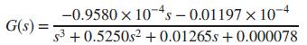
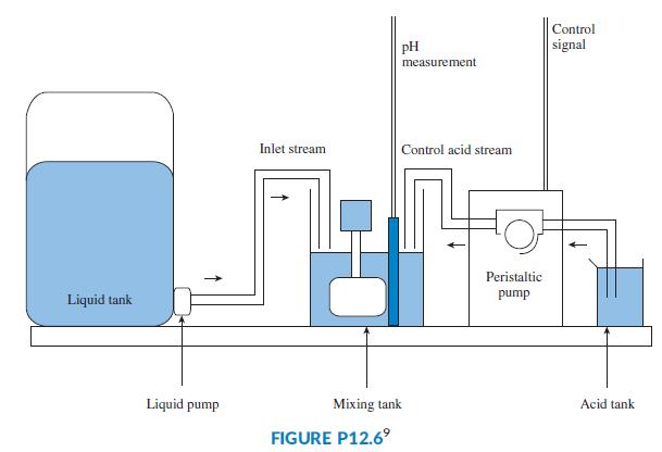
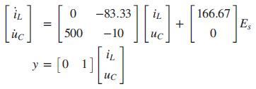
Figure P12.6 shows a continuous stirred tank reactor in which an aqueous solution of sodium acetate (CH3COONa) is neutralized in the mixing tank with hydrochloric acid (HCl) to maintain a particular pH in the mixing tank.The amount of acid in the mix is controlled by varying the rotational speed of
In the dc-dc converter of Problem 67, Chapter 4 (Van Dijk, 1995), with L = 6 mH, C = 1 mF, R = 100 Ω, a 50% PWM duty cycle, and assuming the system’s output is the voltage across the capacitor, the model can be expressed as
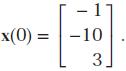
a. Design an observer for the dc-dc converter of Problem 36. The observer should have time constants 10 times smaller than those of the original system.b. Simulate your system and observer for a unit step input using Simulink. Assume that the initial conditions for the original system are The
a. Design an observer for the neutralization system using the continuous stirred tank reactor of Problem 35. The observer should have time constants 10 times smaller than those of the original system. Assume that the original state variables are those obtained in the phase-variable
a. Redesign the dc-dc converter system of Problem 36 to include integral control.b. Simulate your system for a step input using Simulink and verify that the specifications are met. In particular, verify that the system has zero steady-state error.
The use of feedback control to vary the pitch angle in the blades of a variable speed wind turbine allows power generation optimization under variable wind conditions (Liu, 2008). At a specific operating point, it is possible to linearize turbine models. For example, the model of a three-blade
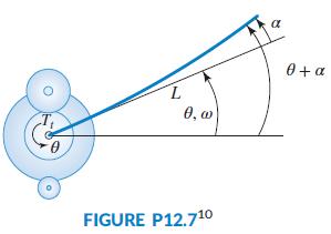
The study of the flexible links, such as the one shown in Figure P12.7, is important because of their application to the control of flexible lightweight robots (Saini, 2012). The flexible link angle is deflected by a servomotor. It is assumed that the base angle, θ(t), and the tip angular
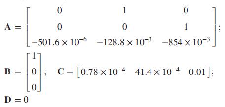
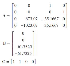
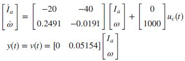
We want to use an observer in a textile machine to estimate the state variables. The 2-input, 1-output system’s model is ẋ = Ax + Bu; y = Cx, where (Cardona, 2010)a. Find the system’s observability matrix OMz and show that the system is observable.b. Find the original system’s
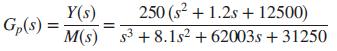
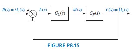
Let the plant in the drive system with an elastically coupled load (Thomsen, 2011) shown in Figure P8.15 bewhere Y(s) = ΩL(s), the load speed. Represent Gp(s) in observer canonical form. Then design an observer for it, such that it responds 10 times faster than the output, y(t), if GC(s) = KP. 250
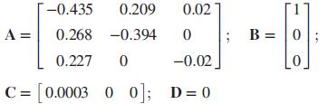
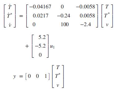
The linearized model of HIV infection when RTIs are used for treatment was introduced in Chapter 4 and repeated here for convenience (Craig, 2004):T represents the number of healthy T-cells, T* the number of infected cells, and v the number of free viruses.a. Design a state-feedback scheme to
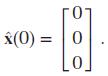
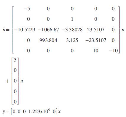
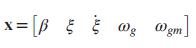
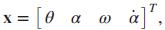
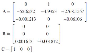
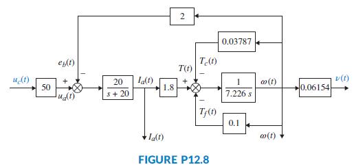
In Problem 32, Chapter 3, we introduced the idea that when an electric motor is the sole motive force provider for a hybrid electric vehicle (HEV), the forward paths of all HEV topologies are similar. It was noted that, in general, the forward path of an HEV cruise control system can be represented
A parabolic trough collector can be designed using state-space techniques. For simplicity, pure time delay will be ignored here, although it could be handled in several different ways. Consider the open-loop transfer function (Camacho, 2012):Design a state feedback controller with integral control
Name two functions that the digital computer can perform when used with feedback control systems.
Derive the z-transforms for the time functions listed below. Do not use any z-transform tables. Use the plan f (t) → f *(t) → F*(s) → F(z), followed by converting F(z) into closed form making use of the fact that 1/(1 - z-1) = 1 + z-1 + z-2 + z-3 + ∙ ∙ ∙ . Assume ideal sampling.a.
Name three advantages of using digital computers in the loop.
Repeat all parts of Problem 1 using MATLAB and MATLAB’s Symbolic Math Toolbox.Data from Problem 1Derive the z-transforms for the time functions listed below. Do not use any z-transform tables. Use the plan f (t) → f *(t) → F*(s) → F(z), followed by converting F(z) into closed form making
Name two important considerations in analog-to-digital conversion that yield errors.
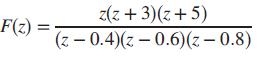
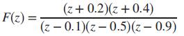
For each F(z), find f(kT) using partial-fraction expansion.a.b.c. z(z + 3)(z+5) F(z) (z - 0.4)(z - 0.6)(z- 0.8)
Of what does the block diagram model for a computer consist?
Repeat all parts of Problem 3 using MATLAB and MATLAB’s Symbolic Math Toolbox.Data from Problem 3For each F(z), find f(kT) using partial-fraction expansion.a.b.c. z(z + 3)(z+5) F(z) (z - 0.4)(z - 0.6)(z- 0.8)
What is the z-transform?
For each F(z) in Problem 3, do the following:a. Find f(kT) using the power series expansion.b. Check your results against your answers from Problem 3.Data from Problem 3For each F(z), find f(kT) using partial-fraction expansion.a.b.c. z(z + 3)(z+5) F(z) (z - 0.4)(z - 0.6)(z- 0.8)
What does the inverse z-transform of a time waveform actually yield?
Showing 100 - 200
of 942
1
2
3
4
5
6
7
8
9
10
Step by Step Answers