New Semester
Started
Get
50% OFF
Study Help!
--h --m --s
Claim Now
Question Answers
Textbooks
Find textbooks, questions and answers
Oops, something went wrong!
Change your search query and then try again
S
Books
FREE
Study Help
Expert Questions
Accounting
General Management
Mathematics
Finance
Organizational Behaviour
Law
Physics
Operating System
Management Leadership
Sociology
Programming
Marketing
Database
Computer Network
Economics
Textbooks Solutions
Accounting
Managerial Accounting
Management Leadership
Cost Accounting
Statistics
Business Law
Corporate Finance
Finance
Economics
Auditing
Tutors
Online Tutors
Find a Tutor
Hire a Tutor
Become a Tutor
AI Tutor
AI Study Planner
NEW
Sell Books
Search
Search
Sign In
Register
study help
engineering
control systems engineering
Control Systems Engineering 7th Edition Norman S. Nise - Solutions
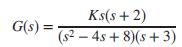
Repeat Problem 36 using MATLAB.Data From Problem 36:Given the unity feedback system of Figure P6.3 witha. Find the range of K for stability.b. Find the frequency of oscillation when the system is marginally stable. Ks(s + 2) (s2 – 4s + 8)(s + 3) G(s) =
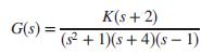
For the unity feedback system of Figure P6.3 withfind the range of K for which there will be only two closed-loop, right-half-plane poles. K(s + 2) G(s) = ( + 1)(s+4)(s – 1)
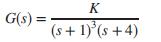
For the unity feedback system of Figure P6.3 witha. Find the range of K for stability.b. Find the frequency of oscillation when the system is marginally stable. K G(s) = (s+1)'(s +4)
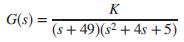
Given the unity feedback system of Figure P6.3 witha. Find the range of K for stability.b. Find the frequency of oscillation when the system is marginally stable. K G(s) = (s+ 49)(s2 + 4s +5)
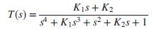
For the transfer function below, find the constraints on K1 and K2 such that the function will have only two jω poles. K1s + K2 T(s) = s4 + K1s + s? + K2s + 1
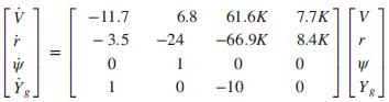
The transfer function relating the output engine fan speed (rpm) to the input main burner fuel flow rate (lb/h) in a short takeoff and landing (STOL) fighter aircraft, ignoring the coupling between engine fan speed and the pitch control command, is (Schierman, 1992)a. Find how many poles are in the
During vertical spindle surface grinding, adjustments are made on a multi-axis computer numerical control (CNC) machine by measuring the applied force with a dynamometer and applying appropriate corrections. This feedback force control results in higher homogeneity and better tolerances in the
Look-ahead information can be used to automatically steer a bicycle in a closed-loop configuration. A line is drawn in the middle of the lane to be followed, and an arbitrary point is chosen in the vehicle’s longitudinal axis. A look-ahead offset is calculated by measuring the distance between
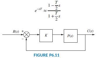
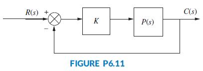
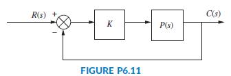
The fluid temperature of a parabolic trough collector (Camacho, 2012) will be controlled by using a unity feedback structure as shown in Figure P6.11. Assume the open-loop plant transfer function is given byUse the Routh-Hurwitz criteria to find the range of gain K that will result in a closed-loop
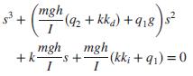
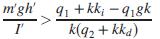
It has been shown (Pounds, 2011) that an unloaded UAV helicopter is closed-loop stable and will have a characteristic equation given bywhere m is the mass of the helicopter, g is the gravitational constant, I is the rotational inertia of the helicopter, h is the height of the rotor plane above the
A position control, tracking with a constant difference in velocity, would yield how much position error in the steady state?
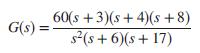
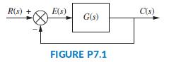
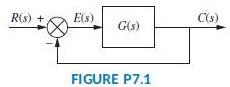
For the unity feedback system shown in Figure P7.1, wherefind the steady-state error if the input is 80t2u(t). 60(s +3)(s + 4)(s +8) s(s + 6)(s+ 17) G(s) =
Name the test inputs used to evaluate steady-state error.
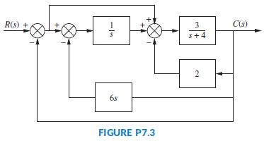
For the system shown in Figure P7.3, what steady-state error can be expected for the following test inputs:10u(t); 10tu(t); 10t2u(t). R(s) + 3 C(s) s+4 2 6s FIGURE P7.3
How many integrations in the forward path are required in order for there to be zero steady-state error for each of the test inputs listed in Question 3?Data From Question 3:Name the test inputs used to evaluate steady-state error.
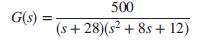
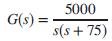
For the unity feedback system shown in Figure P7.1, wherefind the steady-state error for inputs of 20u(t), 60tu(t), and 81t2u(t). 500 G(s) : %3! (s+ 28)(s? + 8s+ 12)
Increasing system gain has what effect upon the steady-state error?
An input of 25t3u(t) is applied to the input of a Type 3 unity feedback system, as shown in Figure P7.1, whereFind the steady-state error in position. 210(s + 4)(s +6)(s+ 11)(s+ 13) G(s) = s3(s+ 7)(s + 14)(s+ 19)
For a step input, the steady-state error is approximately the reciprocal of the static error constant if what condition holds true?
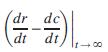
The steady-state error in velocity of a system is defined to bewhere r is the system input, and c is the system output. Find the steady-state error in velocity for an input of t3u(t) to a unity feedback system with a forward transfer function of dr dc dt dt ) +00
What is the exact relationship between the static error constants and the steady-state errors for ramp and parabolic inputs?
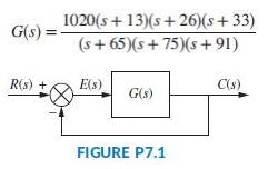
What is the steady-state error for a step input of 15 units applied to the unity feedback system of Figure P7.1, where 1020(s + 13)(s + 26)(s+ 33) (s+ 65)(s+ 75)(s + 91) G(s) = R(s) + E(s) C(s) G(s) FIGURE P7.1
What information is contained in the specification Kp = 10;000?
A system has Kp = 4. What steady-state error can be expected for inputs of 70u(t) and 70tu(t)?
Define system type.
For the unity feedback system shown in Figure P7.1, wherea. What is the expected percent overshoot for a unit step input?b. What is the settling time for a unit step input?c. What is the steady-state error for an input of 5u(t)?d. What is the steady-state error for an input of 5tu(t)?e. What is the
The forward transfer function of a control system has three poles at -1; -2; and -3. What is the system type?
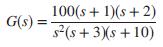
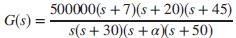
Given the unity feedback system shown in Figure P7.1, wherefind the value of α to yield a Kv = 35000. 500000(s +7)(s+ 20)(s + 45) s(s + 30)(s +a)(s +50) G(s) =
What effect does feedback have upon disturbances?
For a step input disturbance at the input to the plant, describe the effect of controller and plant gain upon minimizing the effect of the disturbance.
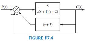
For the system shown in Figure P7.4,a. Find Kp, Kv, and Ka.b. Find the steady-state error for an input of 50u(t), 50tu(t), and 50t2u(t).c. State the system type. R(s) + C(s) s(s + 1)(s +2) (s + 3) FIGURE P7.4
Is the forward-path actuating signal the system error if the system has non unity feedback?
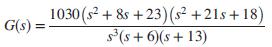
A Type 3 unity feedback system has r (t) = 10t3 applied to its input. Find the steady-state position error for this input if the forward transfer function is 1030 (s2 + &s +23)(s +21s+ 18) G(s) = s(s + 6)(s + 13)
How are non unity feedback systems analyzed and designed for steady-state errors?
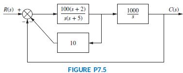
Find the system type for the system of Figure P7.5. R(s) + 100(s + 2) 1000 C(s) s(s + 5) 10 FIGURE P7.5
Define, in words, sensitivity and describe the goal of feedback-control-system engineering as it applies to sensitivity.
Using the Routh-Hurwitz criterion and the unity feedback system of Figure P6.3 witha. Find the range of K for stability.b. Find the value of K for marginal stability.c. Find the actual location of the closed-loop poles when the system is marginally stable. K G(s) = s(s + 1)(s+ 2)(s+ 6)
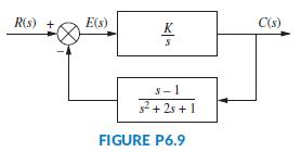
Find the range of K to keep the system shown in Figure P6.9 stable. R(s) + E(s) C(s) K S- 1 2+ 2s + 1 FIGURE P6.9
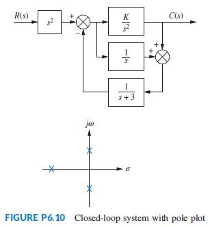
Find the value of K in the system of Figure P6.10 that will place the closed-loop poles as shown. R(s) K C(s) s+3 ja FIGURE P6.10 Closed-loop system with pole plot
The closed-loop transfer function of a system isDetermine the range of K1 in order for the system to be stable. What is the relationship between K1 and K2 for stability? s + KIs+ K2 +K1s3 + K2s² +5s +1 T(s) =
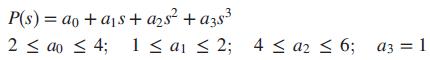
An interval polynomial is of the formP(s) = a0 + a1s + a2s2 + a3s3 + a4s4 + a5s5 + ∙ ∙ ∙with its coefficients belonging to intervals xi ≤ ai ≤ yi, where xi, yi are prescribed constants. Kharitonov’s theorem says that an interval polynomial has all its roots in the left half-plane
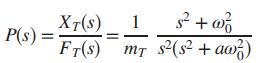
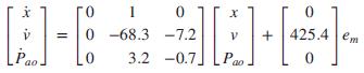
A linearized model of a torque-controlled crane hoisting a load with a fixed rope length iswhere ω0 = √g/L; L= the rope length, mT = the mass of the car, a = the combined rope and car mass, f T = the force input applied to the car, and xT = the resulting rope displacement (Marttinen, 1990).
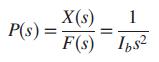
The read/write head assembly arm of a computer hard disk drive (HDD) can be modeled as a rigid rotating body with inertia Ib: Its dynamics can be described with the transfer functionwhere X(s) is the displacement of the read/write head and F(s) is the applied force (Yan, 2003). Show that if the HDD
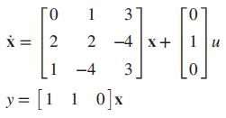
A system is represented in state space asDetermine how many eigenvalues are in the right half-plane, in the left half-plane, and on the jω-axis. 1 2 -4 x+ 1 -4 3 y = [1 1 0]x 1 0]x 3.
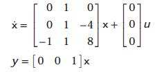
Use MATLAB to find the eigenvalues of the following system: [0 1 01 0 1 -4 x +|0u -1 1 8] y = [0 0 1]x
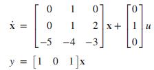
The following system in state space represents the forward path of a unity feedback system. Use the Routh-Hurwitz criterion to determine if the closed-loop system is stable. 1 01 2 x+ -5 -4 -3 y = [1 0 1]x
A Butterworth polynomial is of the formUse the Routh-Hurwitz criteria to find the zeros of a Butterworth polynomial for:a. n = 1;b. n = 2 B.0) = 1 +(-1r()". 2n ,n>0
Repeat Problem 52 using MATLAB.Data From Problem 52:The following system in state space represents the forward path of a unity feedback system. Use the Routh-Hurwitz criterion to determine if the closed-loop system is stable. 1 01 2 x+ -5 -4 -3 y = [1 0 1]x
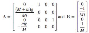
An inverted pendulum, mounted on a motor-driven cart was presented in Chapter 3, Problem 30. The system’s state-space model was linearized around a stationary point, x0 = 0, corresponding to the pendulum point mass, m, being in the upright position at t = 0, when the force applied to the cart u0
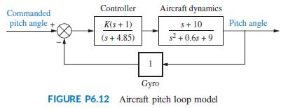
A model for an airplane’s pitch loop is shown in Figure P6.12. Find the range of gain, K, that will keep the system stable. Can the system ever be unstable for positive values of K? Controller Aircraft dynamics Commanded pitch angle K(s + 1) s+ 10 Pitch angle (s+ 4.85) 2 +0.6s + 9 Gyro FIGURE
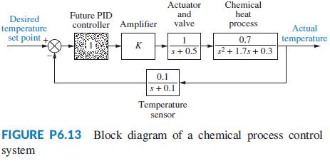
A common application of control systems is in regulating the temperature of a chemical process (Figure P6.13). The flow of a chemical reactant to a process is controlled by an actuator and valve. The reactant causes the temperature in the vat to change. This temperature is sensed and compared to a
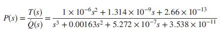
A transfer function from indoor radiator power, Q̇ (s); to room temperature, T(s), in an 11 m2 room iswhere Q̇ is in watts and T is in °C (Thomas, 2005). The room’s temperature will be controlled by embedding it in a closed loop, such as that of Figure P6.11. Find the range of K for
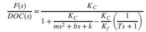
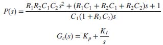
In order to obtain a low-cost lithium-ion battery charger, the feedback loop of Figure P6.3 is used, where G(s) = Gc(s)P(s). The following transfer functions have been derived for G(s) (Tsang, 2009):If R1 = 0.15Ω; R2 = 0.44Ω; C1 = 7200F; and C2 = 170F, use the Routh Hurwitz
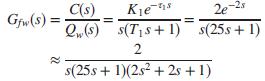
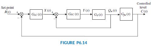
Figure P6.14 is a simplified and linearized block diagram of a cascade control system, which is used to control water level in a steam generator of a nuclear power plant (Wang, 2009).In this system, the level controller, GLC(s), is the master controller and the feed-water flow controller, GFC(s),
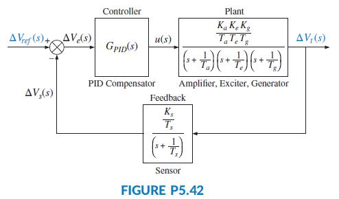
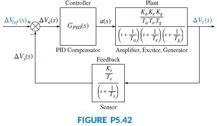
Figure P5.42 Shows the block diagram of an Automatic Voltage Regulator (Gozde, 2011). Assume in this diagram the following parameter values: Ka = 10, Ta = 0.1,Ke = 1, Te = 0.4, Kg = 1, Tg = 1, Ks = 1, and Ts = 0.001. Also assume that the PID transfer function is substituted by a simple integrator,
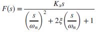
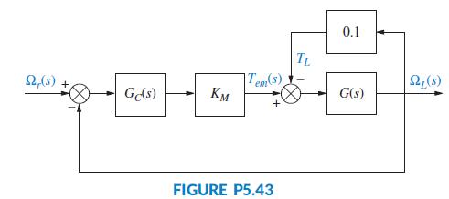
Figure P6.15 shows the model of the dynamics of an economic system (Wingrove, 2012). In this diagram x represents the rate of growth in real Gross National Product (GNP), x0 the long-term trend (dc value) of the GNP, Δx the change over the long-term trend of the GNP, rx the real and psychological
The system shown in Figure P6.16 has G1(s) = 1/s(s + 2) (s + 4). Find the following:a. The value of K2 for which the inner loop will have two equal negative real poles and the associated range of K1 for system stability.b. The value of K1 at which the system oscillates and the associated frequency
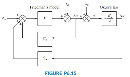
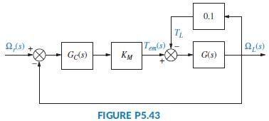
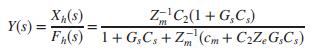
A drive system with an elastically coupled load was presented in Problems 71 and 67 in Chapters 4 and 5, respectively (Thomsen, 2011). That drive was shown in Figure P5.43 as the controlled unit in a feedback control system, where ΩL(s) = the load speed and Ωr(s) = the desired (reference) speed.
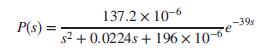
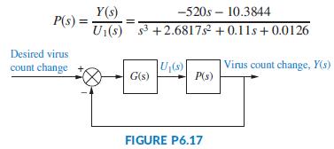
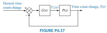
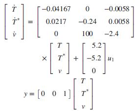
The HIV infection linearized model developed in Problem 84, Chapter 4, can be shown to have the transfer functionIt is desired to develop a policy for drug delivery to maintain the virus count at prescribed levels. For the purpose of obtaining an appropriate u1(t); feedback will be used as shown in
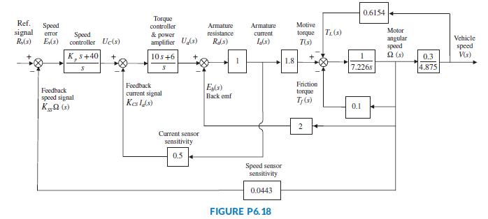
Figure P6.18 shows the HEV system, where parameter values have been substituted.It is assumed here that the speed controller has a proportional gain, Kp, to be adjusted. Use the Routh-Hurwitz stability method to find the range of positive Kp for which the system is closed-loop stable (Graebe,
For the unity feedback system shown in Figure P7.1, wherefind the steady-state errors for the following test inputs:25u(t); 37tu(t); 47t2u(t). 450(s + 8)(s + 12)(s+ 15) G(s) = s(s + 38)(s² + 2s+ 28)
Name two sources of steady-state errors.
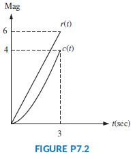
Figure P7.2 shows the ramp input r(t) and the output c(t) of a system. Assuming the output’s steady state can be approximated by a ramp, finda. The steady-state error;b. The steady-state error if the input becomes r(t) = tu(t). Mag c(t) 1(sec) 3 FIGURE P7.2 4,
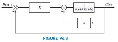
For the system shown in Figure P6.8, find the value of gain, K, that will make the system oscillate. Also, find the frequency of oscillation. R(s) + C(s) K s(s+4)(s+6) FIGURE P6.8
Repeat Problem 33 forData From Problem 33:Given the unity feedback system of Figure P6.3 withfind the following:a. The range of K that keeps the system stableb. The value of K that makes the system oscillatec. The frequency of oscillation when K is set to the value that makes the system oscillate
Given the unity feedback system of Figure P6.3 withfind the following:a. The range of K that keeps the system stableb. The value of K that makes the system oscillatec. The frequency of oscillation when K is set to the value that makes the system oscillate K(s + 4) G(s) = s(s +1.2)(s+2)
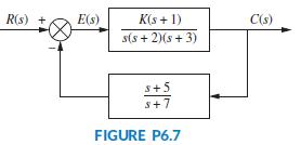
Repeat Problem 31 for the system of Figure P6.7.Data From Problem 13:Use the Routh-Hurwitz criterion to find the range of K for which the system of Figure P6.6 is stable. R(s) + E(s) K(s + 1) C(s) s(s + 2)(s + 3) s+5 s+7 FIGURE P6.7
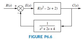
Use the Routh-Hurwitz criterion to find the range of K for which the system of Figure P6.6 is stable. R(s) + E(s) C(s) K(s? – 2s + 2) 1 s2 + 2s +4 FIGURE P6.6
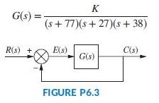
Using the Routh-Hurwitz criterion, find the value of K that will yield oscillations for the unity feedback system of Figure P6.3 with K G(s) = (s + 77)(s+ 27)(s + 38) R(s) + E(s) C(s) G(s) FIGURE P6.3
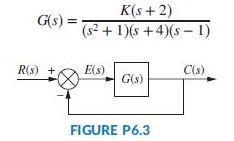
Find the range of gain, K, to ensure stability in the unity feedback system of Figure P6.3 with K(s+ 2) (s2 + 1)(s +4)(s - 1) G(s) = R(s) + E(s) C(s) G(s) FIGURE P6.3
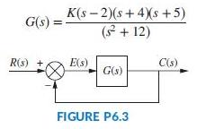
Find the range of gain, K, to ensure stability in the unity feedback system of Figure P6.3 with K(s - 2)(s+ 4(s +5) G(s) ( + 12) R(s) + E(s) C(s) G(s) FIGURE P6.3
Use MATLAB and the Symbolic Math Toolbox to generate a Routh table in terms of K to solve Problem 23.Data From Problem 23:For the unity feedback system of Figure P6.3 withdetermine the range of K for stability. K(s + 3)(s + 5) G(s) : (s- 2)(s- 4) %3D
Repeat Problem 23 using MATLAB.Data From Problem 23:For the unity feedback system of Figure P6.3 withdetermine the range of K for stability. K(s + 3)(s + 5) G(s) : (s- 2)(s- 4) %3D
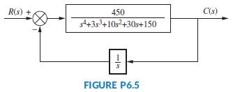
Using the Routh-Hurwitz criterion, tell how many closed-loop poles of the system shown in Figure P6.5 lie in the left half-plane, in the right half-plane, and on the jω-axis. R(s) 450 C(s) 435+10s2+30s+150 FIGURE P6.5
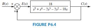
For the system of Figure P6.4, tell how many closed loop poles are located in the right half-plane, in the left half-plane, and on the jω-axis. Notice that there is positive feedback. R(s) + E(s) 18 C(s) g5 + s4 - 753 - 752 - 18s FIGURE P6.4
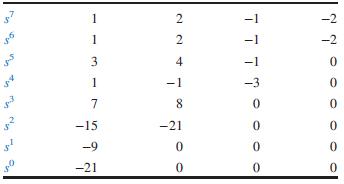
Consider the following Routh table. Notice that the s5 row was originally all zeros. Tell how many roots of the original polynomial were in the right half-plane, in the left half-plane, and on the jω-axis. 2 -2 1 2 -2 4 -1 1 -1 -3 7 8. -15 -21 -9 -21
How do we find the eigenvalues?
Repeat Problem 15 using MATLAB.Data From Problem 15:Given the unity feedback system of Figure P6.3 withtell how many closed-loop poles are located in the right half-plane, in the left half-plane, and on the jω-axis. 8 G(s) s(s6 – 255 - s4 + 2s3 + 4s2 - 8s – 4) 00
Is it true that the eigenvalues of the system matrix are the same as the closed-loop poles?
If a seventh-order system has a row of zeros at the s3 row and two sign changes below the s4 row, how many jω poles does the system have?
Does the presence of an entire row of zeros always mean that the system has jω poles?
If a Routh table has two sign changes above the even polynomial and five sign changes below the even polynomial, how many right-half-plane poles does the system have?
Why do we not multiply a row of a Routh table by a negative constant?
Why do we sometimes multiply a row of a Routh table by a positive constant?
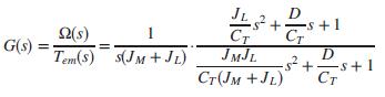
A drive system with an elastically coupled load was presented in Problem 71, Chapter 4. The mechanical part of this drive (Thomsen, 2011) was reduced to a two-inertia model. Using slightly different parameters, the following transfer function results:Here, T(s) = Tem(s) - TL(s), where Tem (s) = the
The purpose of an Automatic Voltage Regulator is to maintain constant the voltage generated in an electrical power system, despite load and line variations, in an electrical power distribution system (Gozde, 2011). Figure P5.42 shows the blockdiagram of such a system. Assuming Ka = 10, Ta = 0.1, Ke
It is shown in Figure 5.6(c) that when negative feedback is used, the overall transfer function for the system of Figure 5.6(b) isDevelop the block diagram of an alternative feedback system that will result in the same closed-loop transfer function, C(s) = R(s), with G(s) unchanged and unmoved. In
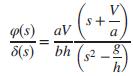
A simplified second-order transfer function model for bicycle dynamics is given byThe input is δ(s), the steering angle, and the output is φ(s), the tilt angle (between the floor and the bicycle longitudinal plane). In the model parameter a is the horizontal distance from the center of the back
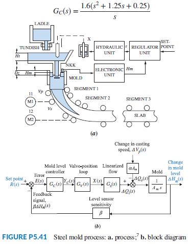
Continuous casting in steel production is essentially a solidification process by which molten steel is solidified into a steel slab after passing through a mold, as shown in Figure P5.41(a). Final product dimensions depend mainly on the casting speed Vp (in m/min), and on the stopper position X(in
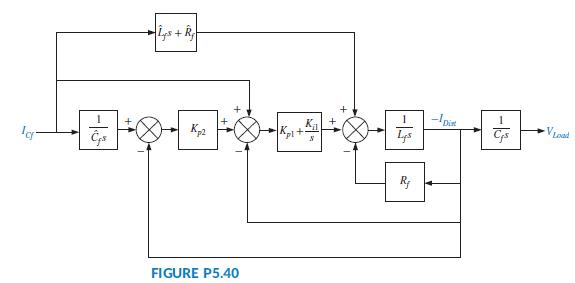
A hybrid solar cell and diesel power distribution system has been proposed and tested (Lee, 2007). The system has been shown to have a very good uninterruptible power supply as well as line voltage regulation capabilities. Figure P5.40 shows a signal flow diagram of the system. The output, VLoad,
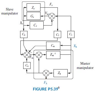
Some medical procedures require the insertion of a needle under a patient’s skin using CT scan monitoring guidance for precision. CT scans emit radiation, posing some cumulative risks for medical personnel. To avoid this problem, a remote control robot has been developed (Piccin, 2009). The robot
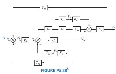
A virtual reality simulator with haptic (sense of touch) feedback was developed to simulate the control of a submarine driven through a joystick input. Operator haptic feedback is provided through joystick position constraints and simulator movement (Karkoub, 2010). Figure P5.38 shows the block
Use LabVIEW’s Control Design and Simulation Module to obtain the controller and the observer canonical forms for: s? + 7s+2 s3 + 9s? + 26s + 24 G(s) =
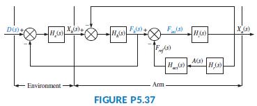
In an experiment to measure and identify postural arm reflexes, subjects hold in their hands a linear hydraulic manipulator. A load cell is attached to the actuator handle to measure resulting forces. At the application of a force, subjects try to maintain a fixed posture. Figure P5.37 shows a
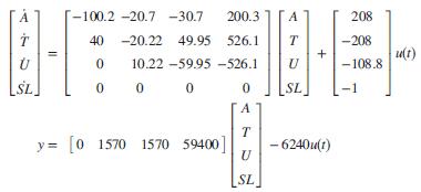
An electric ventricular assist device (EVAD) has been designed to help patients with diminished but still functional heart pumping action to work in parallel with the natural heart. The device consists of a brushless dc electric motor that actuates on a pusher plate. The plate movements help the
The basic unit of skeletal and cardiac muscle cells is a sarcomere, which is what gives such cells a striated (parallel line) appearance. For example, one bicep cell has about 105 sarcomeres. In turn, sarcomeres are composed of protein complexes. Feedback mechanisms play an important role in
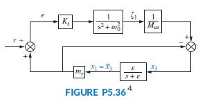
A car active suspension system adds an active hydraulic actuator in parallel with the passive damper and spring to create a dynamic impedance that responds to road variations. The block diagram of Figure P5.36 depicts such an actuator with closed-loop control.In the figure, Kt is the spring
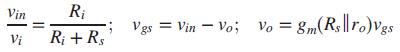
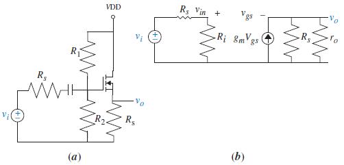
Figure P5.35(a) shows an n-channel enhancement-mode MOSFET source follower circuit. Figure P5.35(b) shows its small-signal equivalent (where Ri = R1 1|| R2) (Neamen, 2001).a. Verify that the equations governing this circuit areb. Draw a block diagram showing the relations betweenthe equations.c.
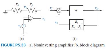
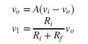
Figure P5.33 shows a noninverting operational amplifier.Assuming the operational amplifier is ideal,a. Verify that the system can be described by the following two equations:b. Check that these equations can be described by the block diagram of Figure P5.33(b).c. Use Mason’s rule to obtain the
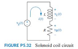
Problem 8 in Chapter 1 describes a high-speed proportional solenoid valve. A subsystem of the valve is the solenoid coil shown in Figure P5.32. Current through the coil, L, generates a magnetic field that produces a force to operate the valve. Figure P5.32 can be represented as a block diagram
Showing 400 - 500
of 942
1
2
3
4
5
6
7
8
9
10
Step by Step Answers